anderekel
Rookie Solder Flinger

Posts: 6
Likes: 0
|
Post by anderekel on Mar 9, 2009 19:47:59 GMT -5
So, I was directed here from another forum (projectguitar) by a friend on there who said I would get much better wiring help here. So here I am. I'm planning on putting this in a guitar in april (beginning of april), but I'm not sure if it'll work at all. David myka put this in a guitar he did, but didn't have the schematic, so I tried to work it out for myself. I think I've done a good job, but I really don't know, I just went by looking at other wiring diagrams and seeing if I can make it work through that. 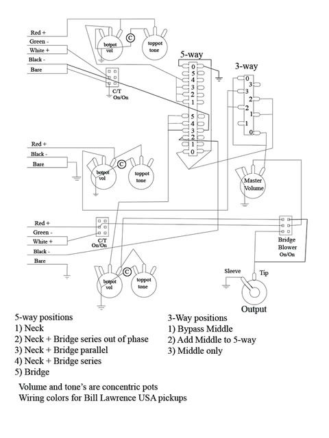 Assuming the whole thing is wired right (probably not, but maybe I got lucky), could I just take the wire leading to the bottom right 3 terminal and put it with the bottom left one and use a single wafer switch. The reason I'm thinkin' it might be wrong is that when I looked at pictures of Myka's wiring, I'm pretty sure I saw a double wafer switch, so yeah. Any help would be really appreciated and thanks for your time.  for some reason I can't make it smaller, sorry. |
|
|
|
Post by newey on Mar 9, 2009 21:43:55 GMT -5
Anderekel-
Hello and Welcome!
The size of your diagram is fine, please don't make it any smaller.
As far as whether it will work as intended, I'm not prepared to say, but someone will be along to vet your diagram.
What are the 2 DPDT switches marked "CT On/On" intended to do?
|
|
anderekel
Rookie Solder Flinger
Posts: 6
Likes: 0
|
Post by anderekel on Mar 9, 2009 21:53:45 GMT -5
They're supposed to be coil taps. North coil for the neck pickup and south coil for the bridge.
|
|
|
|
Post by newey on Mar 9, 2009 22:26:58 GMT -5
OK, I see it now. The bridge one threw me a bit because of the solo switch that it connects to. I'm thinking that the bridge switch needs a connection to ground just like the neck one has.
You could also use single pole switches for those, if you haven't already bought the switches.
|
|
anderekel
Rookie Solder Flinger
Posts: 6
Likes: 0
|
Post by anderekel on Mar 9, 2009 22:39:34 GMT -5
|
|
|
|
Post by ashcatlt on Mar 10, 2009 12:27:41 GMT -5
Your coil taps work fine, assuming those are actually the coils you want to tap.
The 3-way works fine. That's basically standard Tele wiring, and does what you're looking to do.
The "Bridge Blower", that's supposed to overide everything and send the bridge pickup straight to the output all by itself without any volume or tone controls or anything, right? If that's the case, then you'll need to be sure that one end of the bridge pickup is connected to ground when this switch is flipped, regardless of all other switching. Since you haven't got enough poles on this switch, you'll have to wire the bridge pickup so it's "bottom" wire (the black one) is always connected to ground instead of the neck as you have it now. That's not a big deal, and you'll still be able to accomplish all the 5-way combinations you've requested.
Unfortunately, your drawing doesn't seem to get any of them. Well, I think position 1 works, but the rest are pretty weird. Start all over there. Here's some hints. If you move the permanent ground connection to the bottom of the bridge, it leaves 3 loose pickup ends: bridge top, neck bottom, neck top. Each of these goes to the common of it's own pole on the switch. This leaves the 4th common for the "master output" which goes on to the 3-way.
Once you get that sorted out, we'll talk about your volume and tones....
|
|
anderekel
Rookie Solder Flinger
Posts: 6
Likes: 0
|
Post by anderekel on Mar 10, 2009 16:24:37 GMT -5
I fixed the grounds and that and actually happened to find a diagram for exactly what I'm after (with the five way switch that is), so I cheated and went right off that. Looking at it did give me a much better understanding of how the switches work, even if I didn't do it myself. So, here is where it's at now. 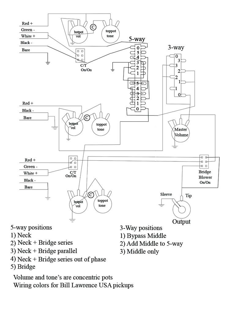 So, I have to ask, what's wrong with the volume and tone pots? I was really sure they were right  And thanks for all the help. I really appreciate it. |
|
|
|
Post by ashcatlt on Mar 10, 2009 22:43:41 GMT -5
That's what I was talking about with the switch. Looks like it works fine now.
The Volume and Tone controls are fine for parallel combinations. They're going to act a little funny in the series positions. I don't have a lot of experience in this area, but there are others around who can explain what to expect, and likely give suggestions for possible fixes.
|
|
anderekel
Rookie Solder Flinger
Posts: 6
Likes: 0
|
Post by anderekel on Mar 11, 2009 1:06:00 GMT -5
Glad to hear the whole thing should work out then. I'm a bit worried about what you say with the volume and tones. I'll probably just leave it unless someone else chimes in with a suggestion on them.
|
|
|
|
Post by ashcatlt on Mar 11, 2009 23:47:13 GMT -5
Well, I was hoping somebody with more experience would step in and explain the V/T thing. Failing that, I tried to search for a thread where we might find a useful explanation. Not having patience to weed through all of the results, I'm going to explain what I think is going on, and how you might fix it.
In parallel mode you're fine. You've done the best you can to isolate the controls to affect only the pickup to which they're assigned.
In series mode (in or out of phase) some different stuff happens. Talking about the volumes first.
I'm pretty sure the Neck Volume becomes a "SubMaster" controlling the overall output from the B*N structure. The bridge pickup has to come through the neck to get out, right? And if the NV tries to divert it to ground...
I think the BV will act as expected to dial the Bridge out of the mix.
The tone controls will act similarly, but with a little twist. Again, your NT is a SubMaster. Your BT is going to roll off the treble from your bridge pickup, while allowing the higher frequencies from the neck pickup to bypass the bridge coil. This creates a sort of "half-parallel" arrangement, which many people appreciate. I think most people prefer to have this happen around the neck pickup though, allowing the brightness of the bridge pickup to shine through a little more.
Now, these may not seem like problems to you. In fact, you might find these features downright handy. If you want to "fix" either of them, you simply need to wire the desired control across the neck pickup itself. To fix both, you'd break that connection to ground where the cap is between the two pots. Bring the bottom (black) wire from the neck pickup to this point in place of ground. Don't solder this to the back of the pot, though.
|
|
anderekel
Rookie Solder Flinger
Posts: 6
Likes: 0
|
Post by anderekel on Mar 12, 2009 13:27:12 GMT -5
Ok, so it's not like it won't be usable at all as is. I think I'll go with it and see how it sounds, I mean, I can always change it up if I don't like it. Thanks for all your help ashcatit. I'll be sure to post up how it works when I get the guitar built and wired up, so mid april or so. |
|


