|
|
Post by ChrisK on Apr 28, 2009 18:13:28 GMT -5
|
|
|
|
Post by sumgai on Apr 29, 2009 0:12:30 GMT -5
Errr, done if you don't wanna hear "the rest of the story", ala Paul Harvey. Most members here know that I'm not a fan of Ted Weber's electronical abilities. Leave it at that, OK? While Chris didn't post this as an advent to starting an argument, I'd like to "clarify" a few points. First off, the common definition of padding is to provide variability to the user. A circuit can be shown in a simplistic representation, and that's what Weber has done, but stopping there gives one the feeling that that's all there is. Suffice it to say, an L-pad is meant to be variable, and you can buy them ready-made for this application. (A link will be shown below.) My other major beef is that he leaves the reader with a pair of formulas, but in point of fact, this is meant for one common application, so why didn't he just post a table, like other sites have done, and let the user choose what to do? The work's been done, why re-invent the wheel? (Again, there's a link below.) Minor gripe - it's not a "Loss or Losser" pad, it's named for the shape of the letter "L", as are the T-pad, the U-pad, the H-pad, the O-pad, etc. This goes the heart of my dislike for Ted, he shows a high degree of ignorance of electrical and electronic history and conventions, and he shows it far too often. I do have good things to say about him as a person, and he has done many good things for the Nutty community, but IMO, educating others about things electronical isn't one of them. Links (from the first page of Google results, searching on "l-pad attenuator"): L-pads defined: dictionary.babylon.com/L_pad (yes, it's the simplified version, but the defintion is spot-on) Various pad configurations: www.uneeda-audio.com/pads/Using L-pads with speakers: www.colomar.com/Shavano/lpad.html (starts getting into the nitty gritty) A calculator for fixed resistor values, plus a table showing some common example values for 4 and 8Ω speakers: www.sengpielaudio.com/calculator-Lpad.htmA retail part from Amazon, at a realistic price, all things considered: www.amazon.com/L-Pad-100W-Stereo-Rated-Shaft/dp/B0002KR0SI (other sources aboond, but Amazon is a known quantity) HTH sumgai |
|
|
|
Post by ChrisK on Apr 29, 2009 11:04:41 GMT -5
Done is.  See, it struck a note, hit a chord, poked the bear, p  d off the Pope, etc. sum gai then posted a bunch of additional stuff here. While I did post info on the "L-Pad" in a response elsewhere a'board, I didn't do it here since I just wanted to add this calculator link to our reference section. Inertia is. Once an object is set into motion, it's got a life of its own. See this and learn, boys and girls. Posting on un-Pope-ular topics can get the fence whitewashed for free. Done is. ;D ;D |
|
|
|
Post by ChrisK on Apr 29, 2009 18:58:22 GMT -5
The Amazon stuff actually comes from Parts Express. Note that an 8 Ohm stereo L-Pad can have its two sections be used in parallel (like terminals to like terminals) with a 4 Ohm speaker to realize a 4 Ohm unit at twice the power (I'm not sure that a 100 watt rating for a stereo L-Pad isn't really 50 watts per side). One can also use a stereo 8 Ohm L-Pad with a 16 Ohm speaker for a 16 Ohm unit at twice the power (again, I'm not sure that a 100 watt rating for a stereo L-Pad isn't really 50 watts per side).  Now, boys and girls, this be a contest; how is this done?  |
|
|
|
Post by cynical1 on Apr 29, 2009 20:51:45 GMT -5
So, if I follow this line of reasoning correctly, a clever fellow could build a little "amp specific" box with a rotary switch and several resistor/cap combinations, set it up between his amp and cabinet and click in anything from driving the amp full in the house late at night to just a bit off the top for smaller venues that don't allow the square footage for full volume...and anything in between...
Interesting...and not terribly expensive to build either...hmmmm...
Happy Trails
Cynical One
|
|
|
|
Post by ChrisK on May 4, 2009 10:46:01 GMT -5
Well, no, I make no mention of specific caps (or inductors). If one wants to present the same reactive load to the amp as the speaker itself, more work needs to be done in calculating this. Furthermore, this attenuator will not have the same effect as an overdriven speaker, since the speaker is not being driven "into the stops" so to speak. But, it will help keep the plates driven hard for "that sound". Folks talk about using a Variac. Discrete input voltage reduction steps can be done using a simple transformer with the primary rated at the mains voltage and the secondary rated at the speaker input current. This was know as the '50s & '60s reversed brownout booster (since the mains sagged a bit back then, and reversed since it was used to boost voltages on a local appliance basis). [[Now, this just might explain why toob amps sounded so "vintage" and "brown" (out) then.....]] For example, if one had an amp that was powered by 120 VAC and drew 240 Watts, and wanted to reduce the input voltage by 6.3 VAC*, one would use a 120 VAC primary 6.3 VAC @ 2 Amp (240 W/120 VAC = 2 A) filament transformer with the primary driven by the 120 VAC mains supply and the secondary in anti-series** with the amp 120 VAC input. *6.3 VAC was chosen since that was an output voltage common on transformers that one used to be able to get, for those a'board that used to work with them. A clever sort will realize that other out voltages can be used. And, other input voltages can be used for places that lacked the common sense to have 120 VAC-based mains systems. 120 VAC will get your attention and possibly kill you. 240 VAC will kill you, and possibly get your attention. **Anti-series means that it is out of phase with the filament transformer and amp power input such that the voltage presented to the amp is 6.3 VAC less than the nominal 120 VAC (113.7 VAC). WARNING: HIGH VOLTAGE. IF YOU DON'T KNOW WHAT YOU ARE DOING, DON'T DO THIS.The way to do this is to wire it up in an electrical box with an inline fuse (  ), a line cord input, and a duplex outlet on the output. Measure the mains input voltage. If the output voltage is 6.3 VAC higher that this, reverse either the transformer's primary wires or the secondary wires, but not both (and not neither). |
|
|
|
Post by ChrisK on May 4, 2009 10:46:27 GMT -5
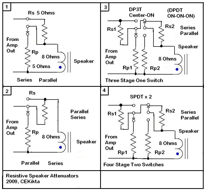
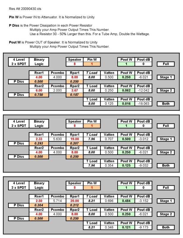
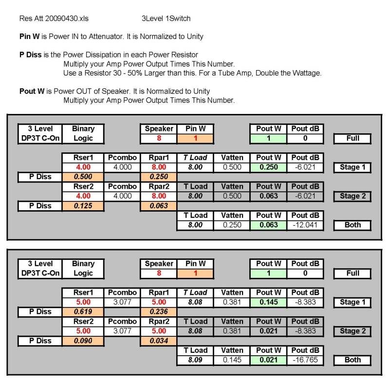
tedfixxIt's actually fairly easy to design a switchable attenuator. In its simplest form, it's two resistors and a SPDT switch. The exact same circuit works for a series first or parallel first topology. Only where you connect the speaker and the input swap between the two. Wow, duality strikes again. #1 is a series resistor first module and #2 is a parallel resistor first module. This leads to two designs; the first one with two switches that gives four settings, and one with a DP3T Center-ON (DPDT ON-ON-ON) switch that gives three. #3 is a 3-Level 1-Switch unit and #4 is a 4-Level 2-Switch unit. I'm sure that other variations and optimizations are possible, but I bore easily (and the VG awaits). I suspect that full-power, 1/4 power (-6dB), 1/16 power (-12dB), and 1/64 power (-18dB) might be more than enough. The Carr Mercury does this, it has 8 W, 2 W, 1/2 W, and 1/10 W. For a 60 Watt amp this is 60 W, 15 W, 3.75 W, and 7/8 W. The bottom view is shown for the switches.  Here are some values for a 4-Level 2-Switch unit. This does full, one stage, the other stage, and both. The first one reduces the power by 1/4 in each of three levels below full power. The second one reduces the power by 1/2 in each of three levels below full power. The third one has some easier resistor values.  Here are some values for a 3-Level 1-Switch unit. This does full, one stage, and both. The first one reduces the power by 1/4 in each of two levels below full power. The second one reduces the power by 1/7 in each of two levels below full power. It uses equal value resistors (because I could). 
|
|