|
|
Post by D2o on Jun 16, 2009 12:38:10 GMT -5
EDIT - { repeat mantra - a fool who never asks remains a fool forever /} ... so, before reading any of this, I am possibly incorrectly using the term slug magnet. I don't mean these:  I am talking about something the shape of this bar shaped object  - but it is flat on the bottom of some pickups:  made me think that if only some of the slug magnets were rotated on their axis' it would be an issue, but your futher elucijudication explanation, Ah - okay. I was still in slug axis rotation mode. Sorry. No, no - no magnet on the bottom. I was saying ... uh, this: 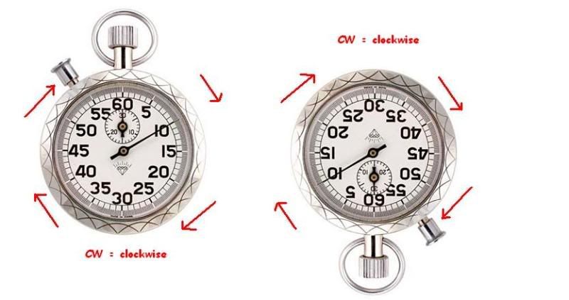 clockwise is clockwise, no matter how many degrees you rotate the clock face in a CW or CCW direction ... that's all. and you have kindly explained that - for the purpose of my misunderstanding question, it really sorta doesn't matter My previous misinterpretation of reversing all of the magnets threw me off, as if rotating the slug magnets on all of the pickups has no effect whereas rotating one on just one of the pickups has an impact (as noted, I see that you said "reversed", not "rotated" - which seems a moot point with respect to a slug magnet.) I believe that is more or lesski what I was trying to get atski, but rotating a single coil slug magnet doesn't matter, and you mean reversing the north and south poles. For what it's worth, I've seen various size magnets on various single coils: some approaching a flat bar shape (i.e. rectangular at the ends and in overall shape) - like the time I pooched my friend's Squier pup and used a MIM strat pickup (if my memory serves me correctly), and definitely like in the "Academy Strat-like Instrument" used in the urthman experiment ; and some that are rectangular in their overall shape, but have square shaped ends - like in the Squier Affinity (a squire's squier) that I have as a sacrificial wiring lamb. Is either of these considered a "normal" shape? 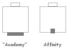 Okay - except rotating the slug magnet is one of those things that, as it turns out, is not one of those things and not what you mean(t). Correct? I don't know if you can use that word in a sentence ... I guess you may be able to, do you feel as if you have possibly elucijudicated me?  Thank you, Chris
|
|
|
|
Post by D2o on Jun 16, 2009 12:41:11 GMT -5
By the way, my apologies Ange - I did not mean to derail your thread.
Sincerely,
D2o
|
|
|
|
Post by angelodp on Jun 16, 2009 13:02:57 GMT -5
No prob, its all good. Now I want to know about coil selection on an HB. Is it possible to have the series/coil-cut/ parallel switch and be able to select which coil is cut, in other words be able to also to toggle the coils.... either or.
ange
|
|
|
|
Post by newey on Jun 16, 2009 14:50:52 GMT -5
Ange-
Not with just a DPDT switch. You would have to pick one or the other coil to be the split coil. Usually, the one you choose would be the one that provides humbucking with whatever other coil(s) it is most likely to be paired with.
With more switching, you could have series/parallel/N coil/S coil options, that is, giving you the ability to split either coil. However, in a std HB, the split coil is likely to sound the same whether it's the N or S coil, since the coils are closely matched. The only real reason to do so is to get the possibility of other hum-cancelling options.
And D2o-
It seems like you are having trouble with the phrase "rotate" with respect to magnets. If you think of it in terms of "flipping the magnet over, such that the N pole is where the S pole used to be", it makes more sense (at least, to me).
For pole pieces, this would imply flipping them end-to-end; for flat magnets on the underside, it implies flipping it over so that the other flat side is against the base of the pup.
After all, with a three dimensional object, there are three possible axes of rotation, and simply saying "rotate" doesn't tell which of the three operations you intend to do. Only one of those three possible "rotations" is going to result in swapping the N for the S pole.
|
|
|
|
Post by ChrisK on Jun 16, 2009 19:36:32 GMT -5
The simplest way to do this is to use a 4PDT toggle switch to switch all four pickup wires like this in the The BuckerBlender where I show it and series/single/parallel for both pickups. Well, in a bridge pickup, especially with the screw coil facing the bridge, there is a discernible difference between the coils due to the differing magnetic materials (screws vs slugs) and the effective pole spacing along the string. The screw poles closer to the bridge are only about half the distance away as the slug poles are. The screw pole coil, for equal wire turns, tends to be a bit brighter. This difference will be exacerbated by position. On a neck pickup, the differential spacing is of little effect (although the magnetic parameters of the flux path still come into play). |
|
|
|
Post by ChrisK on Jun 16, 2009 20:05:21 GMT -5
tedfixx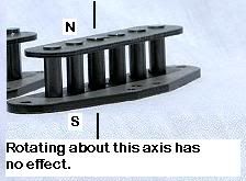 ****************************************************************** 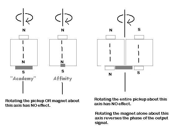 ****************************************************************** 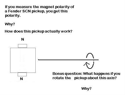
|
|
|
|
Post by D2o on Jun 16, 2009 22:32:13 GMT -5
Thanks Newey, and thanks Chris - much clearer now.
I had to do a little research on the Fender SCN.
The Samarium Cobalt Noiseless is a stacked single coil pickup ... like a sideways humbucker. Cool ... if not a little sneaky.
|
|
|
|
Post by angelodp on Jun 16, 2009 22:48:47 GMT -5
Answer, it remains the same.
ange
|
|
|
|
Post by newey on Jun 16, 2009 23:28:03 GMT -5
How many degrees of rotation are we a'rotatin'?
If it's 180°, then it presumably won't affect the phasing- but may affect the tone since the topside of the pickup will be facing down into the guitar body, and the lower coil is now string-sensing, which it was not intended to do.
I don't know how these work (it seems to be a fairly closely guarded secret on the Fender website). I presume it's 2 stacked coils, stacked in opposition, S pole to S pole, and held in place by some sort of frame to keep them from repelling.
|
|
|
|
Post by angelodp on Jun 17, 2009 3:53:05 GMT -5
On a single coil the polarity is top to bottom orientation, Hum-bucker side to side. How does that affect the fields of the pickups when they are close to each other.  |
|
|
|
Post by ashcatlt on Jun 17, 2009 10:25:53 GMT -5
In a humbucker, the bar magnet's polarity is side to side. The slugs and screws essentially make that bar magnet into something more like one of those horseshoe magnets. For the purposes of string sensing, it's still up and down.
|
|
|
|
Post by D2o on Jun 17, 2009 11:18:41 GMT -5
Look here for patent information on the Fender SCN (it has an exploded view and everything). Figure 2 illustrates that the magnets' polar return path (N to S) is always the center of the pickup. D2o |
|
|
|
Post by ChrisK on Jun 17, 2009 16:10:01 GMT -5
No, the output signal phase reverses since the coil winding direction changes but the magnatic polarity remains the same (you changed 1 thing). Only in a P-90 kind of way (that's a clue there, Sparky). Cool, yes. Sneaky, no. The slugs are actually permalloy ($$) and the magnets are samarium colbalt ($$). The secret sauce in in the controlled gaps between the magnets and the slugs. In essence, it's a very narrow, tall P-90. The structure (not the technology) is similar to the Duncan P-90 Stack (one of my favorite neck pickups). Here's an easier to read and print version of the Stich Patent. www.google.com/patents?id=oymAAAAAEBAJ&printsec=abstract&zoom=4 |
|
|
|
Post by ChrisK on Jun 17, 2009 16:19:02 GMT -5
Actually, relating to side-by-side single coils NOT coupled by a common magnet, there is interaction.
DiMarzio made a Multibucker a few years back. It was a Fast Track and a Chopper, both of which are single coil-sized side-by-side dual rail humbuckers combined into a standard side-by-side humbucker footprint (I have one that I converted to 8 wire plus shield - ugh, too much).
The magnetic ordering goes like this (I may have the N and S reversed, but that's of no concern to my example);
Rail 1 - N
Rail 2 - S
Rail 3 - S
Rail 4 - N
This was done specifically due to the field interaction from close spacing.
|
|
|
|
Post by D2o on Jun 17, 2009 17:31:22 GMT -5
Only in a P-90 kind of way (that's a clue there, Sparky). Or maybe in a P-100 kind of way? (P.S. Your link is way easier to read than the one I posted  ) |
|
|
|
Post by ChrisK on Jun 17, 2009 18:18:07 GMT -5
Yep. Yeah, Willi's web site has a jpg posted. I use google patents since they're pdf's. You can also use www.uspto.gov , but it is fairly churlish to use (what do you expect, it's them same peoples that're bringing us Government Motors). |
|
|
|
Post by angelodp on Jun 18, 2009 11:43:33 GMT -5
Can I get a definition of Absolute Polarity, as it is used in the this article in Artie's scrapbook. www.neighborhost.com/scrapbook/pickup-id.htmlThe only thing we don't know now is absolute polarity. To determine this, we're simply going to repeat the test we just did, but we'll be watching the meter a little closer. Note: It will probably occur to you that the step we're about to perform could have been done at the same time with the previous step. That is correct, and after you've done this once or twice, that will be your natural procedure. I wanted to list them as separate steps just so you'ld be sure to note the different things we're looking for in each step. Again, with the meter leads connected to one set of wires, (and you know which coil you're connected to), bring the screwdriver up against the pole pieces . . . then yank it away. Notice that as you bring it toward the poles, and then yank it away, the meter will indicate a positive voltage in one direction and a negative voltage the other. (On digital meters, you'll see a "minus" sign to indicate a negative voltage.) If the meter reads negative as you approach the poles, and positive as you yank the screwdriver away, reverse the meter leads on the coil wires. Repeat the test. Hopefully, you'll now see a positive voltage as you approach the poles, and a negative voltage as you yank the screwdriver away. The red meter lead now points to the positive coil wire and the black lead points to the negative coil wire. Note this on your paper. Repeat that test for the "other" two wires. Again, note your findings on the paper. If everything has gone as planned, you'll now have a piece of paper that looks like this . . . |
|
|
|
Post by ashcatlt on Jun 18, 2009 12:11:40 GMT -5
It looks like the author of this aritcle has decided that the meter should read a positive voltage as the string moves toward it, and then decided to call that it's Absolute Polarity.
This is really an arbitrary decision. As long as all coils selected together move the same direction, they will be "in-phase".
Some folks insist that speaker should move out (toward the listener) on the initial transient of something like a kick drum, and that it sounds wrong otherwise. I can't tell the difference.
|
|
|
|
Post by ChrisK on Jun 18, 2009 12:23:48 GMT -5
Yes.
It means the "Actual Phasing" of the coil's output signal as a function of reference string movement direction.
As the ferrous mass is moved toward (and always constantly toward just for repeatability) the pole, it will induce an output voltage pulse of a given polarity since only one movement in only one direction is occurring.
All coils in phase with each other will all generate the same polarity of such pulse from such movement in the same direction.
What this enables is the absolute phasing of coils against the reference standard of a common direction of mass movement (and hence an absolute "polarity" if you must).
After all, polarity in AC guitar pickups only means instantaneous phasing (what the absolute signal polarity is at a given moment in time, for a given action, in a given direction, within the flux from a given magnetic polarity, coupled through a coil wound in a given direction).
Things are marked "+" and "-" as voltmeters only indicate in polarity (on the AC scales the meter does you the favor of ignoring phasing/polarity). And, humans have difficulty with the concept of phase.
Someone should start a site on phasing and call it phasebook.
|
|
|
|
Post by ChrisK on Jun 18, 2009 12:37:17 GMT -5
Yep, but it is repeatable, consistent, and hence, standard (even if de facto).
Absolutely! Otherwise, the initial transient will generate a vacuum and tend to suck out the ear wax (and likely brains) of the audience.
This will have the effect of temporarily restoring their hearing just before things go blank forever.
This is to be avoided at all costs, so all speakers are marked with red dots by the positive wiring terminal to ensure that said effect will further impact said material into the audience's noggins.
Or, even a kick drum just generates a damped/decaying sinusoidal-based waveform which has a DC value of zero anyway. (If not, the drum would end up in a different place after each "incident".)
Huh, what, hear?
I do believe that the listener can "feel" a difference from the air pressure though.
|
|
|
|
Post by D2o on Jun 20, 2009 7:20:13 GMT -5
Ange, et al - Ha! Well, live and learn. My sacrificial Squier Affinity was not in the greatest of shape when I "acquired" it a few months ago (the Ping tuners on it were probably worth more than what I paid for the guitar and hardcase). Naturally, it was in need of a little TLC - not the least of which was headstock repair as a result of someone's sloppy installation of the tuners. No problemo for a guitarnut. The N position was weak because the magnet had fallen out of the bottom of the pickup. I popped it back in. Good, but then it was a little thin in the MN position. The resistance reading on the pickups were B = 4.78 ; M = 4.85 ; N = 4.70, so I moved the bridge pickup to middle and vice versa thinking that this might solve the thin sounding MN position problem. No dice so I kinda just forgot about it. Fast forward a couple of months and a couple of foolish question about "n - s polarity" on pickups magnets later and it struck me. I allowed my 9 year old to check the polarity of the magnet and correctly install it, I switched the B & M back, and it's fine. Thanks for putting up with my questions, guys - they may seem inane at times but I assure you that some of it does stick and get applied. Cheers, D2o P.S. I don't know why the resistance on the pickups is not progressively stronger from N to M to B ... you don't suppose it's the manufacturer's quality standards on Squier's or something? |
|
|
|
Post by angelodp on Jun 22, 2009 0:04:01 GMT -5
Adjusted, after conferring with Chrisk. Ok here is a shot at the phase switch with the series/coil-cut/parallel as well. Any comments on whether this will fly. Sorry about the crazy wire paths. I'll clean it up shortly. ange PS finished up my Deluxe 5E3 ... great amp.... Mission kit. 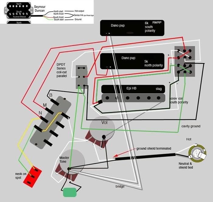 |
|
|
|
Post by newey on Jun 22, 2009 6:04:57 GMT -5
Ange-
Why are you phasing both coils of the HB with what I assume is a 4PDT? If the goal is to get whatever the HB output is (split/series/parallel) OOP with the other pups, a simple DPDT placed "downstream" from the coil selector switch would do the trick with a lot less hassle.
What you have there looks like it will work OK, it just seems like a bit of a convoluted way to achieve OOP.
|
|
|
|
Post by angelodp on Jun 27, 2009 20:30:08 GMT -5
Yah, I suppose, but I wanted to play a bit and try some of these ideas that ChrisK has posted. I am close to trying this and wanted to post the latest version on my graphic to be sure that I am not off track. I should be able to get the usual positions with the 5way, as well as various combos with these extra switches. I have the series/coil cut/ parallel, phase shift for the HB, and neck on. Always like to run it by you guys to insure that the build will be good. thanks 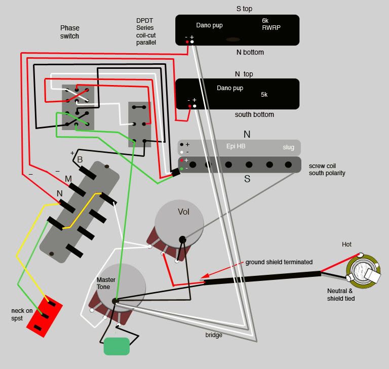 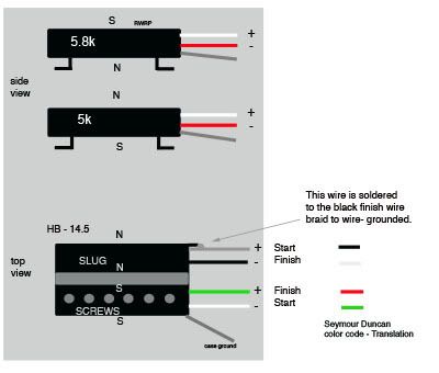 |
|
|
|
Post by ChrisK on Jun 27, 2009 21:37:27 GMT -5
angelo's post is unfortunately the result of some PM's that we're exchanged. I guess in retrospect that these should have been in-thread, but there was some correction and private teaching going on, and sometimes these are best left private (nothing serious, just corrections). As a result, You betcha! You will reverse the phase of whatever is selected. You betcha! However, in this case since the phase reversal is before the series/single/parallel switch, you will reverse the phase of whatever is selected WHILE PRESERVING THE HUM CANCELLATION OF THE SINGLE COIL WITH THE REST OF THE SYSTEM AS THE SINGLE COIL SELECTED VARIES WITH THE PHASE. ChrisK strikes again. 
|
|
|
|
Post by angelodp on Jun 27, 2009 21:53:32 GMT -5
Oh drat, can you help un-convolute this ?
ange
|
|
|
|
Post by newey on Jun 27, 2009 23:42:51 GMT -5
Who was that masked man? ;D
Looks like Chris has got your back on this, Angelo. Maintaining hum-cancellation in the SC position wasn't on my appetizer menu.
|
|
|
|
Post by angelodp on Jun 29, 2009 10:16:49 GMT -5
Ok then I am building this circuit. Back to you with finish shots.
ange
|
|
|
|
Post by angelodp on Jul 2, 2009 22:54:05 GMT -5
Well, Its wired up and there are some interesting sounds, as well as some duds and some issues with the wiring. I will post some details of what is working and what is not. The phase toggle is not working, at least one side is but not the other, and there is some weird stuff going on in other positions. Since there are so many possibilities I will get a bit of a chart going here to help in the trouble shooting.
cheers Ange
|
|
|
|
Post by angelodp on Jul 3, 2009 13:27:51 GMT -5
Here is the actual build graphic. I am going to try and work this out... with your help if possible. Note that the Black wire coming out of the HB also is soldered to the case ground. There are two case grounds as I added the extra wire to complete the four wire set-up. I have a feeling that this is where my problem is. In normal operation with the 5 way switch at the HB, the series/coil-cut/parallel does this in one position the parallel comes on but very thin and weak sounding, the coil cut and series appear to be the same setting. The phase only works in one position. Is this enough info to trouble shoot a bit or ?? What would be helpful 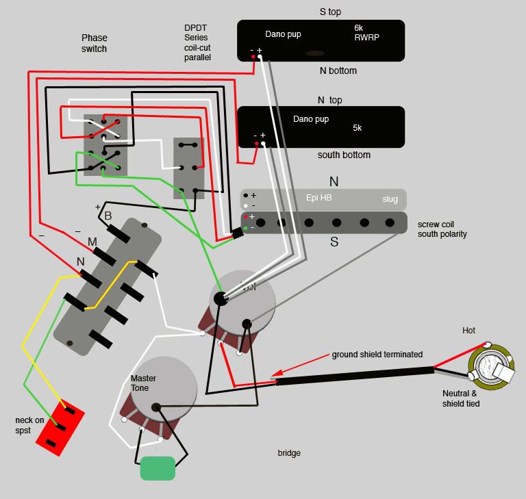 |
|


 - but it is flat on the bottom of some pickups:


 )
)