|
|
Post by roadtonever on Mar 25, 2011 16:43:14 GMT -5
|
|
|
|
Post by sbgodofmetal on Mar 25, 2011 19:58:48 GMT -5
thanks ash for the diagram and johnh i was going to order mine from stewmac.com are those any good
|
|
|
|
Post by roadtonever on Mar 26, 2011 11:09:23 GMT -5
Made some further experiments today, trying a linear pot for the Q-tone control. The linear taper turns out to be my preference. While the audio taper has a pronounced hot spot just above "0" the linear pot was much more gradual. A small draw back with the linear pot is that it's a little too gradual toward the other end of the turn, approaching "10".
Regarding the series cap I may mess with the recommended .1uf value but I'm confident it's already close to ideal so I'm saving this step until I'm wiring the final control.
If nothing else I'll draw my final diagram and source a dual concentric pot and donor wafer pots next.
|
|
|
|
Post by sbgodofmetal on Mar 27, 2011 0:04:22 GMT -5
ok i've updated and even modified my passive EQ circuit it now shows the diode overdrive 'correctly' and instead of a 3way blade it's all on/on's for a active/bypass for each control unit pic coming soon
|
|
|
|
Post by sbgodofmetal on Mar 27, 2011 17:46:35 GMT -5
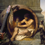
and now i give you version 2.0  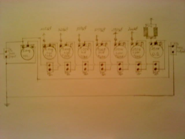 passive 6 band EQ+passive Overdrive (via 2 low voltage drop shotsky Diodes) it has a 1meg master volume two 1meg pots for high tones two 500k pots for mid tones and two 250k pots for low tones and one 250k pot for the passive overdrive all connected to seven 2pole on/on switches for independant tone selecting and custom tone mixing two 1/4 mono input/output jacks the capacitors in my diagram are .001uf, .020uf, .039uf, .047uf, .050uf, and .100uf but you can use what ever you like its all preference the same goes for the pot values as well 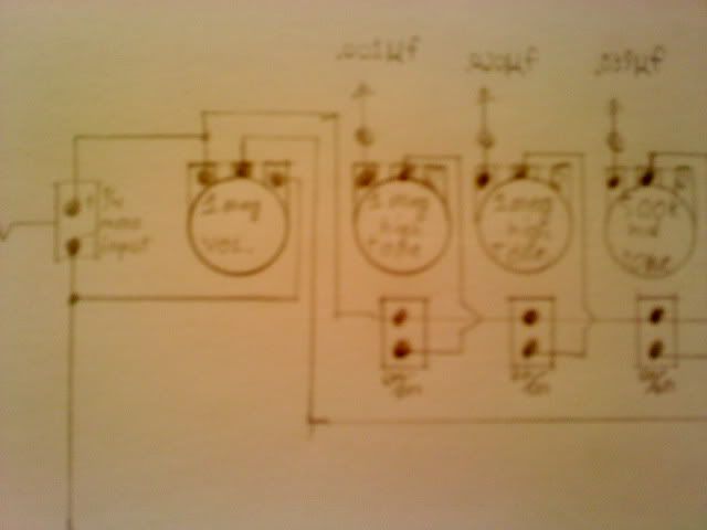 As you can see here the output from the volume travels down the top lug of each on/on switch as a bypass wire and lug and the bottom lug is wired to the tones output lug so on each switch up=bypass, down=circuit is active and in use  And here you can see the continuation of the bypass/active circuit chain and the passive overdrive unit. The passive overdrive unit is just simply 2 low voltage drop shotsky Diodes wired to a tone pot in place of the tone capacitor that would normally be there it will give a subtle tube like drive sound very useful in jazz/blues/ and classic rock |
|
|
|
Post by roadtonever on Mar 31, 2011 18:19:29 GMT -5
ChristoMephisto, I got a reply from Becky Lawrence today:
Hope this helps.
|
|
|
|
Post by ChristoMephisto on Apr 1, 2011 17:44:42 GMT -5
Right on, thx
When I get a chance, I'll start back on my tele and put the Keystones back in, and a 6 position rotary switch
|
|
|
|
Post by roadtonever on May 19, 2011 11:31:47 GMT -5
Sharing my final diagram for a dual-control inductor based EQ circuit. The values were carefully chosen after spending hours trying pots of varying values and tapers. The taper I chose was linear for both Q-Tone and Vari-Q controls. While it's not as smooth as audio taper overall it avoids hot spots. The diagram is compatible with audio taper pots as well. In practical use the dual controls let you set a wide range of tones a unavailable with a single control. Vari-Q lets you control the bass boost as it were when the main Q-tone control is floored. It's useful for the neck pickup when an upright depth is not desired but still sweet and organicly articulate. With both pickups activated in either series of parallel a super lively and articulate tone can be set. Bridge pickup can be set unusually bright if you want to do that. I have the controls on a dual concentric Fender by CTS with wafers swapped to my values. The end result feels a lot like active controls. Look Ma', no batteries! ;D I'll upload some better demo clips to the sound samples section in the near future.  |
|
|
|
Post by roadtonever on Jul 2, 2011 6:14:51 GMT -5
I was pulling out my hair trying to figure out how to add a master tone control to the diagram above until I found a diagram for the Torres midshaper. So here's the addition of a master tone to the diagram above:  Seems to work as intended functionally when I made the connections with alligator clips. Anyone wanna proof it and I'll add it to the modules section? EDIT: The more I learn about how these circuits work the more I realize how bad the Vari-Q control describes the function. Vary-L more appropriate? |
|
|
|
Post by roadtonever on Jul 4, 2011 1:39:57 GMT -5
To stumulate discussion, some diagrams by Torres and Rothstein:   |
|
|
|
Post by roadtonever on Jul 9, 2011 18:40:02 GMT -5
Re-upping the last working diagram revised with better descriptive control annotations and some standard component symbols to humor the EE types. Needs look-over. |
|
|
|
Post by sumgai on Jul 9, 2011 20:32:26 GMT -5
RTN, You want me to be humored? OK, I'm chuckling. Mildly, to be sure, but you can call me "pleasantly amused". As in, why have you persisted for the last umpty-squat iterations on using the Volume pot as a rheostat instead of a potentiometer?  IOW, why are there two leads going from that pot to the output jack's Hot terminal?  sumgai |
|
|
|
Post by roadtonever on Jul 9, 2011 21:34:06 GMT -5
You want me to be humored? OK, I'm chuckling. Mildly, to be sure, but you can call me "pleasantly amused". I'm glad to hear that! As in, why have you persisted for the last umpty-squat iterations on using the Volume pot as a rheostat instead of a potentiometer? IOW, why are there two leads going from that pot to the output jack's Hot terminal? Well it's the most functional way I could implement the controls. Whenever the volume control was configured as a voltage divider the tone control would behave like a second volume control. Do you think the controls I want make up a more complex circuit than what I've drafted so far? Anyway how's the weather in the Vatican this time of year? We're you involved in the pardoning of The Beatles perhaps? ;D |
|
|
|
Post by sumgai on Jul 9, 2011 22:18:28 GMT -5
RTN, Well, I won't tell you that can't use a rheostat, or that you must use a voltage divider, I'll only say that if this is the way it works best, then so be it. Odd? Yeah, but so what.... so long as you get paid at the end of the gig - that automatically makes you right. ;D You've answered my question sufficiently, that earns a +1.  sumgai |
|
|
|
Post by roadtonever on Jul 10, 2011 18:31:44 GMT -5
There was an easy to read drawing of the Gibson L6-s all along:  For future reference, scemamatics for L6-S and L9-S   I think I've got some alligator lead time ahead of me.... |
|
|
|
Post by ChristoMephisto on Jul 11, 2011 10:52:14 GMT -5
You could use a rotary switch to control which tone circuit you want to use instead of leaving each one on. The Schaller tone circuit here... guitarnuts2.proboards.com/index.cgi?board=wiring&action=display&thread=4665it has a passive type of low cut, band pass and treble cut on a rotary switch. looks like you can easily add pots to the caps for your eq'ing, even add a p/p pot to add an inductor in series with the cap and pot for a different sound. |
|
|
|
Post by asmith on Jul 11, 2011 11:00:29 GMT -5
looks like you can easily add pots to the caps for your eq'ing... . |
|
|
|
Post by roadtonever on Jul 11, 2011 12:46:19 GMT -5
This should correspond to the Gibson scheme:  Now begins the effort to fuse that with what I started with:  Stay tuned... |
|
|
|
Post by roadtonever on Jul 11, 2011 12:51:36 GMT -5
You could use a rotary switch to control which tone circuit you want to use instead of leaving each one on. The Schaller tone circuit here... guitarnuts2.proboards.com/index.cgi?board=wiring&action=display&thread=4665it has a passive type of low cut, band pass and treble cut on a rotary switch. looks like you can easily add pots to the caps for your eq'ing, even add a p/p pot to add an inductor in series with the cap and pot for a different sound. Thanks but none of those use the inductor I'd want to use. Seems worthy of study though. Gotta learn to read those schematics... |
|
|
|
Post by roadtonever on Jul 13, 2011 10:50:12 GMT -5
Simply adding the variable resistor in parallel with the inductor-cap in the L6-S scheme seemed to work fine and dandy.  I took the precaution of trying some variations in case the the new connections would break my controls somehow. Discovered these variations seemed functional:   Closer to BL Q-filter diagram homepages.ihug.co.nz/~online/nocaster/blqfilter.jpg Ditto above Are there any significant differences? The last two seemed smoother/duller but it might be my mind playing tricks on me.... |
|
|
|
Post by roadtonever on Jul 15, 2011 3:38:09 GMT -5
|
|
|
|
Post by asmith on Jul 15, 2011 5:00:15 GMT -5
Using a Western cliche to stimulate activity, eh.  I suggest you download circuit modelling software (like 5spice, which is what JohnH uses, or something similar), and try the different setups, looking at the frequency responses. That'll probably help you in your quest to learn to read schematics. |
|
|
|
Post by roadtonever on Jul 15, 2011 5:54:40 GMT -5
Just poking fun at the state of this thread, possibly too soon. Thanks for the 5spice tip.
|
|
|
|
Post by sumgai on Jul 15, 2011 12:04:26 GMT -5
Roady's bandmate, running down the street shouting "I can't take it anymore", after being asked to check out Roady's tone at band practice, yet again. |
|
|
|
Post by roadtonever on Jul 15, 2011 16:16:14 GMT -5
Who told you?  |
|
|
|
Post by roadtonever on Jul 24, 2011 3:29:47 GMT -5
I've been using the top diagram from reply#49 for a while after a recommendation on another forum and I'm pretty satisfied. The 500k volume turned out to make the tone honkey in intermiate tone control settings so I've gone back to 250k. Another catch I discovered was that the inductance goes down a bit when the "mid" control is turned down which can be nice for the neck pickup but less so for the bridge pickup(hello ice-pick), a tone cap switching module would be beneficial in this scheme. Here's a clip with with bridge pickup selected Mid control at 0 Tone control at 2-3 and a fresh set of D'addario stainless steel Half-rounds(NOS): soundcloud.com/roadtonever/bright-gloom |
|
|
|
Post by cynical1 on Jul 24, 2011 9:56:55 GMT -5
I can see that being a very useful tone if you were the slap and pop type of guy...
However, I believe this would really wake up a set of flatwounds...now you're getting me interested... Guess I'm gonna have to route for more then the p-bass pickups on the bass project.
This is my favorite tone from the entire series so far.
Happy Trails
Cynical One
|
|
|
|
Post by roadtonever on Jul 24, 2011 13:17:46 GMT -5
Cynical1, I'm glad my experiments might have inspired you. Funny you mention waking up a set of flatwounds, the first time I replaced a tone cap with an inductor I thought "sounds like rounds" using flatwounds at the time. They way I see it now, for the bridge pickup, with a cap in series with the inductor, the lows and low-mids are louder relative to mids which makes it easier to use without being put-off by a usually thin an honky tone.
|
|
|
|
Post by roadtonever on Aug 26, 2011 14:31:14 GMT -5
A small update of my take on the Bass Q-filter controls. Main difference from my earlier drawing is that I've convinced myself that the log taper pots work better overall for a number of reasons.  For the sake of completeness I'll mention the 100k pot is the only addition over to the standard Q-Filter diagram. I find it comes in real handy when a more articulate neck position tone is desired. I have still not felt compelled to try a different cap than .01uF, it establishes a corner frequency of ~300Hz which makes perfect sense to me. As for the conundrum of having a regular tone control play nice with the inductor controls I add it at the pickup selector like on a Strat. If a pickup selector is not used you could add it to the right-most lug in the 250k pot in the drawing below (Lifted from Gibson L-6S scheme). I've tried it both ways and I'm not sure I hear a difference so I'll assume it's electronically equivalent. I might be wrong though.  Also worth noting beside the tone-shaping it helps achieve tone control consistency. Consider a pair of identical pickups combined in parallel, inductance halves. The desired resonance you get on either pickup alone goes out the window. With the inductor control you can chose the tone cap for the parallel combined position, when the same resonance is desried for individual settings you bring in the inductor. |
|
|
|
Post by roadtonever on Aug 27, 2011 4:32:28 GMT -5
Forgot about this one:  Should be functionally equivalent to L6-S fragment above as far as controls go(according to corresponding Gibson schematics). |
|


 IOW, why are there two leads going from that pot to the output jack's Hot terminal?