ddsebrian
Rookie Solder Flinger

Posts: 18
Likes: 0
|
Post by ddsebrian on Jan 20, 2012 16:36:41 GMT -5
Hello all! I've searched this forum and many other sites but didn't found any topic with the wiring I want... I have a H-S-H guitar with dimarzios on neck and bridge. 1vol, 1 tone. I have a super switch and 2 push-pull available The wiring i want would give the follow: 1. Bridge series 2. Bridge parallel 3. Neck inside coil + Bridge inside coil (parallel) 4. Neck parallel 5. Neck series Tone Push-pull out 1. Bridge coil tap (inside coil) 2. Bridge inside coil + middle 3. * 4. Neck outside coil + middle 5. Neck coil tap (outside coil) *This position 3 could be whanever is easier/possible... but preferably envolving neck and bridge. 'Middle only' is ok if really needed. (i won't ever use middle only) ** The pos 1 and 5 are the ones that matter to me here.. neck and bridge split. Thank you so much for the attention! Just ask me for any additional information. Cheers from Brazil.  |
|
|
|
Post by newey on Jan 20, 2012 22:30:05 GMT -5
ddsebrian- Hello and Welcome to G-Nutz2! The Superswitch can certainly be wired as you want. But you are asking too much from a single push/pull pot. A push/pull pot is a double-pole switch. You can use it to switch two things at once. You want it to split the neck HB to one coil, split the bridge HB to one coil, and turn the middle pickup on/off. That's three things. Now, we've got some pretty clever folk around, and maybe someone can figure out how to do this with only a single P/P pot. But I'm not seeing it. However, you did say that you had two push/pull pots. And, with using single volume and tone controls, you've got spaces to put exactly two push/pull pots.  If you use both, one can handle splitting the bridge and neck to single coils (both neck and bridge would be split together). The second one can turn the middle on/off. This means you can add the mid to any of the settings on the 5-way switch, and add it to the single coils when the other P/P is pulled out. The mid would never be on by itself (as per your wishes). At least, I think this could be done- I have to think through whether there's a problem with splitting the neck HB to the inside coil at position 3 of the 5-way, and then splitting to the opposite coil with the P/P. This may present an issue, not sure yet about that. Anyway, that's what I would think could come closest to what you want. It gets all the settings you desire, but you have to manipulate one more switch to get them. |
|
|
|
Post by asmith on Jan 21, 2012 9:43:42 GMT -5
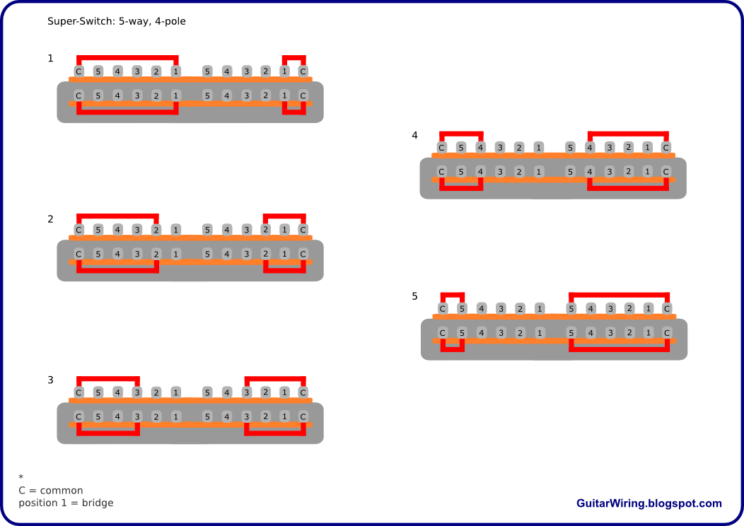
Newey is right, providing one thing. You wire the superswitch as per his own diagram here. Then it's certainly true that you're asking too much of a push/pull. However, what if we could combine two of the push/pull functions in to one? If we stick 'split the Neck' and 'split the Bridge' into one pole, we only need the two poles our push/pull provides. This requires that we use a pole of the Superswitch to determine what we're cutting, before we cut it. And as per Newey's diagram linked to above, we don't have any more poles left. Therefore, we need to play a little jiggery pokery with the superswitch diagram. And if we do... Old image, with an error If you label the superswitch selections 1-5 from left to right, that gives: 1. Bridge series 2. Bridge parallel 3. Neck inside coil + Bridge inside coil (parallel) 4. Neck parallel 5. Neck series Tone Push-pull out 1. Bridge coil tap (inside coil) 2. Bridge inside coil + middle 3. Off 4. Neck outside coil + middle 5. Neck coil tap (outside coil) Now that does what you ask for, with everything "off" in the 'push/pull up' mode, third position. It has been a struggle to try and do anything with that third position in the alternate mode. The "nothing on" position is a good practical option if you're leaving a guitar on stage. |
|
|
|
Post by sumgai on Jan 21, 2012 13:44:19 GMT -5
Ace, I dunno whether to bestow upon you the Mike Richardson award for coloring outside the lines in terms of complexity, or to swamp you with a bowl of wet noodles for what you did on the upper left-side pole - in positions 1, 2 and 3, the Neck outer + and - are tied together! Was this perhaps a bit of forgetful mislabelling, or do they do things differently over there in your part of the world?  sumgai |
|
|
|
Post by asmith on Jan 21, 2012 13:54:16 GMT -5
Was this perhaps a bit of forgetful mislabelling, or do they do things differently over there in your part of the world? Nope SG, it's intentional. The Neck Outer coil is never on in the scheme in positions 1 to 3, and as far as I figured, shorting it out on the hot side, similar to the modus operandi of your own Four-Way Tele, is a useful way to start freeing up other poles on the Superswitch to do what we needed to do with it. I'd gladly accept the award, but I'm already stocked so high on crayons... I love it's title. I sometimes wonder how often Mike might lurk. |
|
|
|
Post by newey on Jan 21, 2012 15:32:43 GMT -5
See, ddsebrian, I told you we had some clever types around here . . . |
|
|
|
Post by sumgai on Jan 21, 2012 20:55:05 GMT -5
Ace, I see that you also do not subscribe to the School of the Dreaded Tone Suck. That's a good thing. Too bad I jumped the gun, sorry 'bout that.  And nice play on words, it took me a second reading to 'get it'. ;D Mike does occasionally drop by, but it's been a year and a half since he's actually logged in. Sigh. He was one of the good ones. sumgai |
|
|
|
Post by reTrEaD on Jan 22, 2012 0:07:07 GMT -5
It has been a struggle to try and do anything with that third position in the alternate mode. The "nothing on" position is a good practical option if you're leaving a guitar on stage. I can believe that. This thing is very convoluted because of the specifications called for in the OP. Requiring parallel and series connections on different positions of 5way eats up poles. Then you have to make three rights to go left, to accomplish some otherwise simple tasks. Maybe ddsebrian will be satisfied with position 3 in the alternate mode, but it amounts to a dead position. Accidentally bumping the 5way into this position will be far more annoying than just having the wrong tone. As far as this being a practical option, rolling the volume down to zero works just fine for a guitar left on stage. The sad thing about this, is how little it accomplishes. There are never any more than 2 coils used at any one time. Not that this is inherently a bad thing. It's just that one could do so much more with coil pairs if the series/parallel task was delegated to a push-pull. And since there are 2 push-pulls available, the second could be used as a "single" switch. I guess it all depends on how fixated one is on having specific things in specific positions, at the expense of keeping things straight and sensible. |
|
|
|
Post by JohnH on Jan 22, 2012 2:28:18 GMT -5
I think its time to post reTreAds version of my HHH design at this point. (i hope you dont mind reT!) Its a superswitch and two push pull pots, but it gets 5 series combos, 5 parallel combos and 5 single coil sounds, based on selecting five humcancelling pairs of coils, including Bridge Hb, M/B, M/N, B/N, Neck hb and then wiring them is series, parallel or just one coil.  It gives more bang/buck! (BTW, congrats to asmith for figuring out how to do the original request) John |
|
|
|
Post by reTrEaD on Jan 22, 2012 14:07:10 GMT -5
(i hope you dont mind reT!) I don't, but was hesitant to post it. asmith has spent a good bit of time making something that fits the original specs. I fear we may be stepping on his toes. |
|
|
|
Post by asmith on Jan 22, 2012 14:43:39 GMT -5
bullcrap. I like puzzles.
Me solving a puzzle and ddsebrian finalising what he wants in his guitar aren't the same thing.
|
|
ddsebrian
Rookie Solder Flinger
Posts: 18
Likes: 0
|
Post by ddsebrian on Jan 22, 2012 18:46:35 GMT -5
Thank you all for the answers!
asmith, your solution is perfect for me...
I really don't mind pos 3 to be a kill switch.
Actually I prefer a killswitch than 'middle only'!
Are you sure about the '5. Neck coil tap (outside coil)'?
I'll study the diagram you posted, than i'll post here my conclusion (with dimarzio colors and etc) for you to correct if necessary, is it ok?
JohnH, i think i've seen this diagram of yours before.
It indeed gives more options, but I'll only use the options that i said in this thread, and that 'disposition' i posted would be really perfect for my needs!
Thank you all again, and sorry for my 'awayness' these days =)
(Sorry also for any grammar mistake..)
|
|
ddsebrian
Rookie Solder Flinger
Posts: 18
Likes: 0
|
Post by ddsebrian on Jan 22, 2012 23:48:59 GMT -5
I've end up with this scheme.. But yes.. even if I have researched a lot about it in the last years, I'm still a noob in wiring So, I'm pretty sure I made some mistakes (minor or major) in this scheme, even in the basic DiMarzio colors and location of the pickup wires... 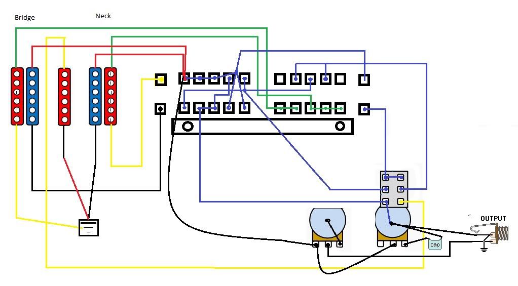 DiMarzio color example: static.zoovy.com/img/guitarelectronics/-/diagrams/color_codes/dimarzio.jpgasmith, can you examine this diagram (the whole details if possible) and tell me if it's gonna work as we intended it to? thank you for the patience! |
|
ddsebrian
Rookie Solder Flinger
Posts: 18
Likes: 0
|
Post by ddsebrian on Jan 22, 2012 23:49:20 GMT -5
Great Paint skills, huh? lol =)
|
|
ddsebrian
Rookie Solder Flinger
Posts: 18
Likes: 0
|
Post by ddsebrian on Jan 23, 2012 0:42:00 GMT -5
I should be smart and base my scheme on JohnH's scheme instead of just reading and guessing where the + and - are in the pickups...
Anyway... i see the probable inversion in the colors, but can you confirm it to me?
|
|
|
|
Post by asmith on Jan 23, 2012 4:19:57 GMT -5
D,
Your neck + wires are swapped. If you move the green wire to the blue pickup (inner), and the red wire to the red pickup (outer), then the diagram is A-OK.
BTW, if you'd prefer that "3. Neck inside coil + Bridge inside coil (parallel)" is on both modes, instead of the 'off' position, we can do that as well.
Not just me who can answer questions and check diagrams as well; feel free to just ask for help generally, lots of people here are more than happy to lend a hand. I don't want anyone to feel left out.
Cheers
|
|
ddsebrian
Rookie Solder Flinger
Posts: 18
Likes: 0
|
Post by ddsebrian on Jan 23, 2012 13:30:25 GMT -5
This option of neck inside + bridge inside in both modes would complicate the wiring or not much? I'm thinking about the difficulty to soldering this scheme... not that easy As you said, anyone is free to check, respond, and add anything =) About the inverted neck wires: Are you sure I just have to exchange the green with red in the neck? The white and black would change pairs this way I've came with this based on JohnH's scheme and other dimarzio ones I've searched. Is it ok? Or the neck wires are still inverted? 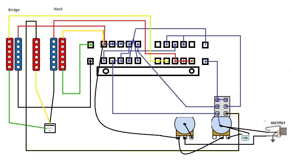 Thank you all! |
|
|
|
Post by JohnH on Jan 23, 2012 14:19:55 GMT -5
Good luck with your scheme. Dont forget to ground the back of the volume pot, and add a wire to ground the strings/bridge
Watch out also for getting phase correct. Unless you can be sure, it is not obvious which neck and bridge coils will combine inphase and hum cancelling with the middle. If you reckon that blue and red indicate north and south, you want to get that alternating pattern as in the diagram. You can test magnetic polarity using another magnet, such as a refridgerator magnet, or, if the pickups are out of the guitar, place them face to face to see which poles attract or repel.
John
|
|
ddsebrian
Rookie Solder Flinger
Posts: 18
Likes: 0
|
Post by ddsebrian on Jan 23, 2012 16:12:43 GMT -5
Yeap. I forgot about polarity.
To be hum cancelling the polarity of both active pickups should be different? + with -?
|
|
ddsebrian
Rookie Solder Flinger
Posts: 18
Likes: 0
|
Post by ddsebrian on Jan 23, 2012 16:21:32 GMT -5
 Looking at this I have the impression that neck and bridge are inverted in the super switch in our scheme. Not? |
|
|
|
Post by asmith on Jan 23, 2012 19:42:37 GMT -5
This option of neck inside + bridge inside in both modes would complicate the wiring or not much? In my whacked opinion it simplifies the wiring - but only slightly. I had a brief check over your drawings but just thought it'd be simpler to pen it out as needed. This is the "Inner coils on in both modes" version. The colours are DiMarzio-based. 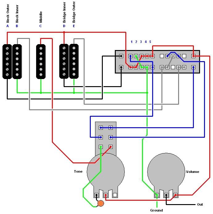 I took the liberty of deciding your Neck Outer coil and Bridge Inside coil would be screw poles. I seem to get the general consensus on the board that lone screw coils seem to be preferred over lone slug coils? I don't know. Somebody with more experience might chime in on this for me? This means that to get your hum-cancelling combinations, your middle pickup should be the same polarity and phase as your slug coils. I've done some Googling and I think that might be the case... again, somebody with more experience would do better to answer this question. Any problems, make some noise. Cheers |
|
ddsebrian
Rookie Solder Flinger
Posts: 18
Likes: 0
|
Post by ddsebrian on Jan 23, 2012 20:26:22 GMT -5
Wow!
That's nice...
About the slug/screw thing..
My bridge pickup is Tone Zone that naturally have the screws towards the bridge (outside) and slugs as the inside.
I'd have to invert the pickup physically?
If yes, I'd prefer to leave it as it is.. less mess.
No problem if this would lead to the outter coil of the bridge on in the tap mode...
But i think that the middle pickup should combine with inner bridge (slug, in this case) for it to be hum cancelling.
The neck pickup is Evolution Neck that have no slugs nor screws..
I tested the way the neck and bridge are installed combined with middle pickup in positions 2 and 4 hum-cancelling is:
Neck outside + middle. Bridge inside + middle.
A noob question again:
The 1,2,3,4,5 of the superswitch in your scheme is the real position to be installed? I ask because the other superswitch diagram I posted says C 54321
Thank you for the immense help and patience!
|
|
|
|
Post by newey on Jan 23, 2012 22:46:50 GMT -5
It's C 1 2 3 4 5 1 2 3 4 5 C C 1 2 3 4 5 1 2 3 4 5 C But if you flip it upside down, it's: C 5 4 3 2 1 5 4 3 2 1 C C 5 4 3 2 1 5 4 3 2 1 C Symmetric is. |
|
|
|
Post by reTrEaD on Jan 23, 2012 23:57:25 GMT -5
A noob question again: The 1,2,3,4,5 of the superswitch in your scheme is the real position to be installed? I ask because the other superswitch diagram I posted says C 54321 It all depends on what 1 (or 5) means to you. For some, "1" refers to the lever being pushed toward the bridge. For others it means the lever being pushed toward the neck. From the perspective of the rear of the switch, with the neck being on the left of the diagram you posted in reply #19, "1" would be with the lever pushed toward the neck. I prefer the opposite convention. Where "1" is when the lever is pushed toward the bridge. I'm not sure about asmith's diagram. His pots are drawn as though looking through the mounting plate, rather than viewed from the rear. |
|
|
|
Post by asmith on Jan 24, 2012 6:03:35 GMT -5
I'm not sure about asmith's diagram. His pots are drawn as though looking through the mounting plate, rather than viewed from the rear. Christ, I don't know how I live with myself sometimes. For clarity: This is the wiring of the pots how I originally wired it, as if the pots are facing up through the pickguard / body. This is how you wire the pots if they're upside down, the pickguard / body upside down as well. Hopefully that clears things up. Don't worry about the Superswitch positions. There's been a lot of discussion over the years about which way round those positions are referred to. In fact, here's a post from our own Newey in my very first thread here at GN2 that says Fender describes the positions as 5: Neck and 1: Bridge. Originally I just put them on the diagram so we'd be able to refer to them easily if needs be; "1 = A * B" in that first diagram, for example. Description of current pickup arrangement No problem. DiMarzio makes their pickups so that the red and black wires are for the screw coil (reference). Here's the recoloured diagram, with redrawn pickups to be closer to what you have. In line with the discussion about pot wiring and switch-numbering, I've reversed the pots so that it's as if the pickguard / body was upside-down, and I've numbered the switch 5-1 from left to right. 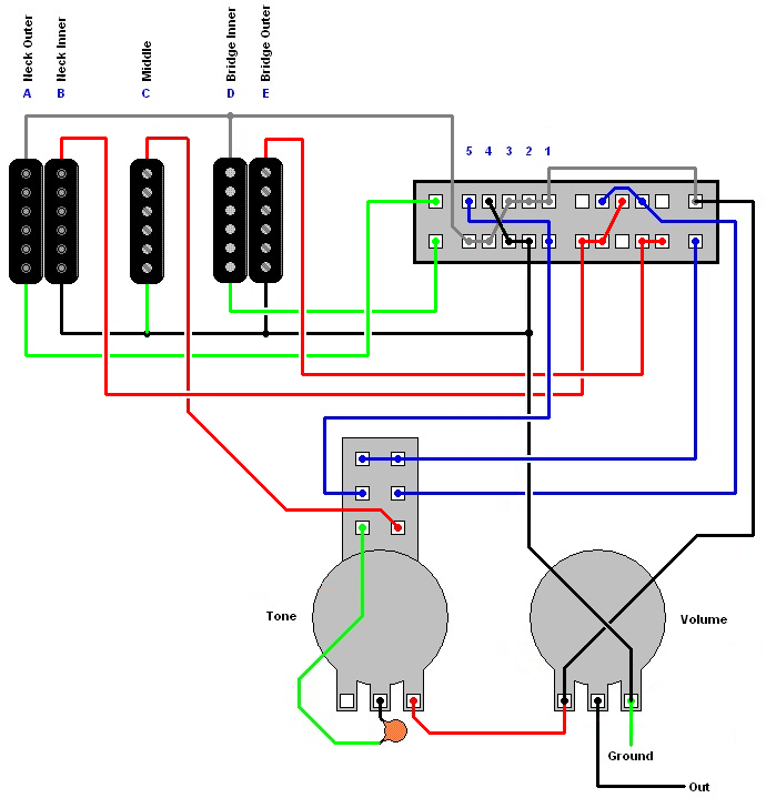 As always, any issues, shout up. Cheers |
|
|
|
Post by reTrEaD on Jan 24, 2012 11:15:05 GMT -5
No problem. DiMarzio makes their pickups so that the red and black wires are for the screw coil (reference). Hmmm. I know this is wrong, from experience. Yet the diagram in the pdf you linked to supports your statement. Puzzlement is. Reading again, I discovered the reason for this disparity: IMPORTANT—Although the Bluesbucker™ is similar in
appearance to other DiMarzio humbuckers, there are
several important differences in wiring and mounting.
Please read these instructions carefully before installing
your new pickup. The Bluesbuckerâ„¢ has red, black, green and white wires.
The screw coil is the “hot†coil with red and black wires.
Note: This differs from other DiMarzio humbuckers. The
arrangement of the coils on the Bluesbuckerâ„¢ is shown in
the diagram to the right. Apparently the Bluesbucker is a bit of an oddball. These are the wiring instructions for most DiMarzio pickups: www.dimarzio.com/sites/default/files/diagrams/4Conductor.pdf |
|
|
|
Post by JohnH on Jan 24, 2012 14:30:33 GMT -5
I think that in these situations with various pickups, it pays to work out the wiring colours, phase and magnetic polarities for yourself
Wire colours for each coil - tap test with a screwdriver tip with a pair of wires going to an amp. When you tap the pole of the coil connected to the connectedwires, it will sound louder than if you tap the other coil
Magnetic polarity - placing pups face to face, or using another magnet to see if they attarct or repel . Its not really important what is actually north and south, just the relative polarities of coils
Phase - use screwdriver pull off test - see reference section
cheers
John
|
|
|
|
Post by reTrEaD on Jan 24, 2012 22:15:42 GMT -5
Good advice, John. Even if it's only for confirmation of what you already (think you) know, it's very easy to do.
|
|
ddsebrian
Rookie Solder Flinger
Posts: 18
Likes: 0
|
Post by ddsebrian on Jan 25, 2012 2:15:55 GMT -5
The green and white wires are indeed the screw pole (south) ones  (source: I've confirmed it in the results of previous instalations I did with these dimarzio pickups I have. Don't know how dimarzio could put the wrong information on manual! I will do what JonhH taught before soldering just to learn to do it =). It's a really simple method and would help to be 100% sure of the wire colors of any pickup. JohnH: What method (before soldering) could I use to discover/confirm which wire is + or - in a single pickup? asmith: I understand the relativity with the 1-5 naming. But I got confused to the actual position wiring of the SSwitch lugs. I'll try to figure that out, and ask it later if it's the case. What I'm really having trouble to understand is the Super Switch functionality. As I see here, in pos1 seems like both bridge and neck would be 'on'. Thinking that when the selector would be in 1, the lugs 'on' will be the four 1 and the four common. Could you guys help me to understand it? One thing I didn't mention yet. This push-pull is the most simple one. A 'on-on', right? I think your last diagram is the closest to the 'final one' we could get! only except that the green+white are the south and black+red are north. BTW which software do u use to make your diagrams? they're awesome! did you see how childish were the ones I made?  Thank you all |
|
|
|
Post by JohnH on Jan 25, 2012 5:13:41 GMT -5
JohnH: What method (before soldering) could I use to discover/confirm which wire is + or - in a single pickup? The + and - are only relevant in a single pickup if one of them is grounded to the case. But if all coil wires are seperate from ground, as in a normal single coil pickup, and in a humbucker with 4-conductor wiring, then it only becomes important in relation to other coils so that they are all in phase when they should be. This is where the Screwdriver Pull-off test can be used to get them all working together.. Basicly, you will take one coil or pickuop and decide which wires are going to be + and -, and then work out the wires for other coils so that they combine in phase. John. |
|


