printjunky
Rookie Solder Flinger

Posts: 6
Likes: 0
|
Post by printjunky on Apr 30, 2012 9:45:10 GMT -5
I have an old "skylark" guitar - a Japanese guitar made in the late 70s/early 80s by the famous Mastumoku factory (which also famously made some now well-regarded Washburn, Epiphone, Aria, Vantage, Electra, Univox and Westone guitars.) It's beautifully made, neck-through, high quality hardware, and as you'll see, interesting electronics. Interestingly, this guitar was sold through JC Penny catalog, and I remember very vividly as a teen, lusting after this guitar. I finally got one, last year (about 30 years later!) for a very reasonable price because it had a very easy to fix neck crack (and no pickups). Now I want to finish getting it up and running! Here is some information about the guitar from a Web site about these guitars from this factory. www.matsumoku.org/models/skylark/skylark_info.htmlMine is the 857-2588 (the blue one) Here are some diagrams of the preamp part of the original circuit for that guitar: www.matsumoku.org/models/skylark/2588_wiring.htmlAs you can see this guitar had a preamp onboard. That has been removed from my guitar.It also came to me without pickups and missing two pots. I have diagrammed how the electronics were when the guitar came to me (attached). I have some ideas how I might wire the new pickups and pots in, but I thought I would try to get a second opinion about the wiring from you. My basic goal is to have a couple of good humbucker tones, and a couple of good single-coil tones. I can see how I might easily achieve this just by using two of the switches. But with this much hardware I should be able to do even more variations on tone.I may add back in a preamp/buffer some day, but not at this time. I want to get this thing up and playing. SOME NOTES ON THE DIAGRAM: WIRE COLORS: Grey=White Pickups, Input and pickup selector switch wire colors are accurate. Most of the rest of the wires are varied in color to enhance contrast (most of them are actually green in the guitar (All of the grey wires are white.) The rotary switch might be 6 position, I can't remember, and I am not in front of the guitar right now. Tone Neck and Tone Bridge are just ideas (not installed yet) so if anyone has an interesting idea, I could change their purpose. I believe all of the switches are basic DPDT ON/ON switches, though I've only tested the two with the crossover wiring (A & B). So have at it. I'll be mining the threads to see what inspiration I get. And thanks for any input! Oh, and in case you're wondering, I am putting a pair of these in it. Loved their sound on some demos I heard. www.guitarfetish.com/GFS-Pro-Tube-Lipstick-Humbucker-Pickup-Cool-Chimey-Tone_c_111.htmlA demo of them: Thanks again! Shawn 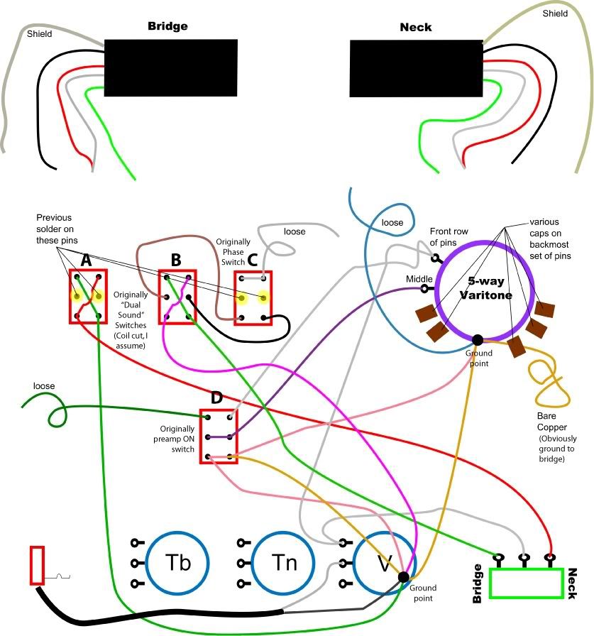 |
|
|
|
Post by newey on Apr 30, 2012 22:50:15 GMT -5
printjunky- Hello and Welcome to G-Nutz2! Me, too. 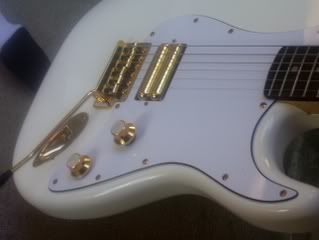 As for your diagram, I haven't had the chance to go through it thoroughly yet, so this is preliminary only. But I think you've got it backwards. Switches "A" and "B" are phase switches; A is for the neck pickup, "B" is for the bridge. Looks to me like the points you have in yellow are, in fact, where the pickups were previously wired in- where you noted "previous solder on these pins". The neck black wire would go to the left-hand side of switch "A" (as it is oriented on the diagram); the green wire goes to the other side. The bridge pickup was (apparently) wired into switch "C" first, I first thought that "C" was for a coil cut, but I can't really work that out. And two phase switches would be redundant for 2 pickups . . . So, let's let someone else weigh in, at least until I can study this more. We are, however, going to need more specificity as to the varitone, we'll need to see what the various connected (and unconnected) lugs are. |
|
printjunky
Rookie Solder Flinger
Posts: 6
Likes: 0
|
Post by printjunky on May 3, 2012 18:45:11 GMT -5
Newey, Thanks for the reply. Took a couple of days to get back to it, but here's the diagram of the rotary switch. 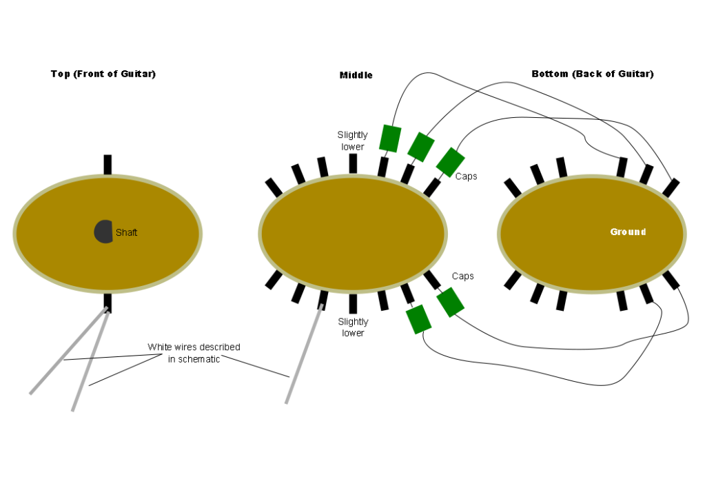 |
|
printjunky
Rookie Solder Flinger
Posts: 6
Likes: 0
|
Post by printjunky on May 3, 2012 18:48:59 GMT -5
Also, I agree that the wiring seems to be set up as you describe. On the diagram, I was referring to the switches' original use. I have no way of knowing if the wiring has been changed (but assume the crossover wiring being indicative of phase rev, it has). And in fact, I have no sure way of knowing what Matsumoku was referring to when they said "Dual Sound" switches. Coil cut is just an assumption.
Also, because it's incomplete (and maybe even incorrect) it might be impossible to asses what any previous hacker was intending (so far I can't). So of course, I might have to, and am prepared to start by desoldering.
Thanks again,
Shawn
|
|
|
|
Post by newey on May 3, 2012 20:55:28 GMT -5
Aha- I didn't realize we were dealing with a probable rewiring by someone other than the factory . . . Are you sure you want to rewire this in some way other than per the factory (whatever that was . . . )? I don't know that these will ever have any real collector's value or not; some Japanese-made axes from that era do move the needle quite a bit. But maybe you should consider that, if you rewire it to non-original specs, it may lose any value as a collectable. In which case, the answer would be more research and attempting to repair rather than reconfigure. Up to you, of course, but something to consider.  If we're talking rewiring, you can certainly lose the redundant phase switches on both pickups. Then the logical thing would be to have a single phase on either the neck or bridge, with a coil-cut switch for each. Or, alternatively, a series/parallel switch for each. My white strat above has the single HB wired for series/parallel. I originally tried it as a coil cut but I thought it sounded much better with both coils in parallel than with the coil split option. Or, you could make like Solomon and "split the baby"- one pickup (probably the neck) gets the coil cut treatment, and the other gets the series/parallel treatment. |
|
printjunky
Rookie Solder Flinger
Posts: 6
Likes: 0
|
Post by printjunky on May 3, 2012 21:17:49 GMT -5
Understood, and this model, because it was made for one run, does occasionally "move the needle" into the above $500 range. But I doubt I'll ever part with it, and it's not a likely collector with the repaired neck.
And based on the config as you noted, I'm about 90% sure this is a PO job.
Though I do have a deep affinity for some other WAY (IMHO) underrated Japanese models. Ibanez Studio/Artist/Musician are just BEAUTIFUL. Especially in polar white. I remember the day I saw the first ad for that Polar White line. And that color just gets better (golder) with time. And I love a bunch of these Mastsomuko models. Some amazingly well-constructed stuff came out of Japan around 1980. On par with the best I've ever seen.
Anywhoo, to revert to stock, I'd also have to find or build a preamp exactly like the one in there.
It's kind of the way I think of my 1973 Land Rover daily driver. I'll keep keeping it nice, but I have no intention of ever making it into something I have to store in a garage/display case and only take out on sunny Sundays and hope not to scratch. So a daily driver it'll be.
And with this setup, I have numerous options. Based on youtube vids, I agree that I like P/S better than cut.
I'm guessing my best bet under those circumstances is to desolder everything (except the caps, maybe) and start from scratch.
I guess I was hoping 8/10 of my work had been done for me. No such luck, looks like.
I'll mull my options, maybe throw a few more questions at you, then dive in.
Thanks agin,
Shawn
|
|
|
|
Post by newey on May 3, 2012 22:12:05 GMT -5
I would think you could just leave the varitone as is, and just wire to/from it as per the diagram- minus the connections to the preamp switch.
Adding 2 tone controls along with the varitone might deserve some thought. You might want to set it up such that the varitone bypasses the tone pots, so that you don't get the setting with both pickups on, two tone pots and a volume pot, plus the capacitance of whatever is selected on the rotary all in circuit at once.
|
|
printjunky
Rookie Solder Flinger
Posts: 6
Likes: 0
|
Post by printjunky on May 6, 2012 2:57:16 GMT -5
So here where my mind is going. Phase: Works only when both pickups are selected, puts the pickups out of phase. Ser/Par: Switches pickups to parallel from series. ?: Obviously not sure, but I'm interested in seeing what something like two outer coils sounds like, maybe. VAritone in/out. Not sure if it would work to have something like two separate systems, varitone with it's own pot and a regular tone circuit, or some other idea. This seems to allow a lot of control, but if one of the caps on the varitone is a standard (.022uf) tone cap, then having the standard tone circuit would be redundant. I'll start working up a prospective schematic and see what I come up with. 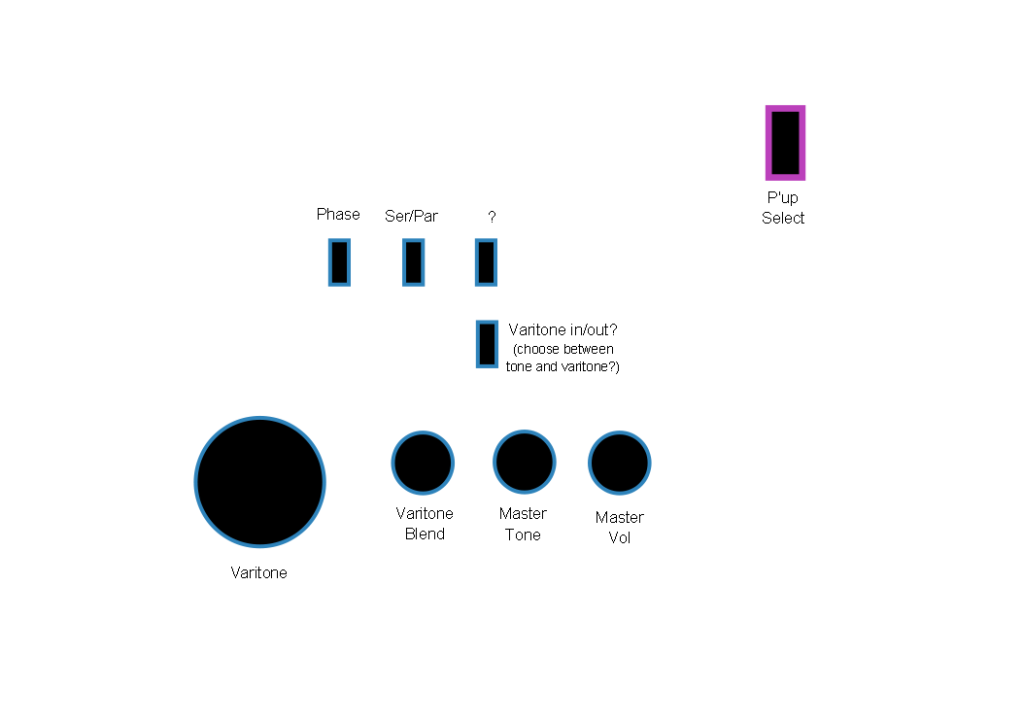 |
|
|
|
Post by newey on May 6, 2012 8:56:19 GMT -5
I'll forgo several obvious punchlines here . . . . ;D In any event, we've established that you're both a guitarist and a masochist. This may become important as we move forward. Based on your diagram, it would seem to be so. And it has only 5 caps attached, which suggests that you can use the 6th position as a bypass position. I suspect this was how it was originally wired. If so, it means you don't need a separate switch to select the Varitone on/off. But you might want one to be able to preset the Varitone and then be able to quickly access that preset by flipping a single switch. See above. The Varitone with a .022 cap would be like the tone control at "0" (well, not quite, if the tone pots are out of circuit with the Varitone- but close). You could then preset your tone control at, say, "7", and flip back and forth. Also note that, when we talk about this thing as a "Varitone" that, while these are often wired just using a variety of caps, the original Gibson Varitone™ circuit used an inductor in conjunction with the caps- a bit of a different circuit. You might consider rewiring the rotary that way as well. Just another option to think about. I do not know what you are intending with the "varitone blend". I thought the idea was separate tone controls for the two pickups? If you are thinking to use a blend control so as to give varying amounts of "unaltered" signal with the Varitone signal, I suspect that's not going to sound much different than turning down your tone pot(s). You can certainly used one DPDT switch to cut both HBs to a single coil so as to do this. I don't know (i.e., maybe but I'm not sure) whether this could also override the pickup selector so that flipping the switch always gives you the outside coils of both regardless of the pickup selector's position. You might need another pole on the switch to do this. The way I'm envisioning it, it's just a coil-cut switch that simultaneously cuts both pups to the outer coil of each. Meaning that, with the pickup selector set to "neck pup only", you'd have a neck SC and the same at the bridge setting, only in the center position would you have both outer coils at once. |
|
printjunky
Rookie Solder Flinger
Posts: 6
Likes: 0
|
Post by printjunky on May 7, 2012 0:30:04 GMT -5
The idea behind the Varitone blend, was that I could basically have two separate, switchable master tone circuits, one standard (for .... simplicity's sake? (though how hard is it to remember that pos. 1 on the 6-way is .022 or whatever?)), and one with multiple caps.
Seemed like being able to vary the Varitone would be more beneficial. Maybe that's not true.
I guess in theory, if I have a switch for the (lets call it) Cap Selector, subbing for the bypass position I could add another cap value to the 6th position.
(agreed, Varitone is not quite the correct term without the inductor, which I will probably leave out for now.)
Probably, big-picture, I'd be perfectly happy with a simple 1 vol, 1 tone, pickup selector and one of the ways to get a single coil sound.
But that seems like a waste on this guitar, and not nearly masochistic. enough. Like when I needed to do some wiring on the Rover, and thought "While I'm in here, I should probably reversibly graft in a circuit breaker protected mid-90s Caddy fuse box and relays."
With the reading I'm doing, I'm starting to understand a bit more about the order in which things need to go, and where in the circuit things should/could go. I think I can start working up a new schematic. I'll post it when I do.
Thanks again!
|
|
|
|
Post by sumgai on May 9, 2012 0:10:31 GMT -5
But that's...... not nearly masochistic enough. I detect a fellow GuitarNut in the making!! ;D sumgai |
|


