Xochitl
Apprentice Shielder

Posts: 34
Likes: 0
|
Post by Xochitl on Aug 10, 2012 10:42:53 GMT -5
|
|
|
|
Post by reTrEaD on Aug 10, 2012 15:14:18 GMT -5
Hi Xochitl, The image for your complete circuit doesn't show up for me.  |
|
|
|
Post by newey on Aug 10, 2012 19:37:45 GMT -5
Flickr has always been hit or miss as far as posting photos here. Not all hosting sites "play nice" with the software Proboards uses.
Imageshack and Photobucket are the two services that we know work properly; others may or may not.
|
|
|
|
Post by newey on Aug 11, 2012 6:38:52 GMT -5
The Skydrive link takes me to a password-required sign-in page. Still no diagram!  |
|
Xochitl
Apprentice Shielder
Posts: 34
Likes: 0
|
Post by Xochitl on Aug 11, 2012 8:02:26 GMT -5
My first post has been modified. I hope I fixed it for good now!  |
|
|
|
Post by reTrEaD on Aug 12, 2012 5:44:43 GMT -5
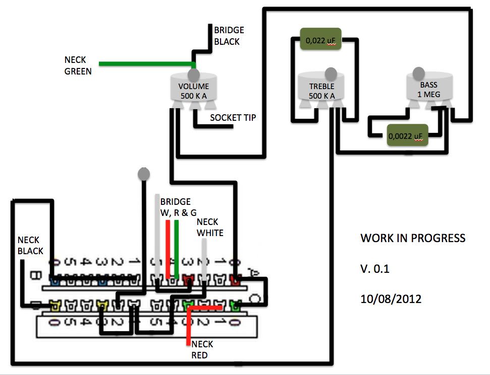
The tone control section has serious problems.
The treble cut needs to be in parallel with the signal and shunt to ground. You could disconnect the right hand lead of the cap from the CCW terminal of the pot and connect it (the right hand lead of the cap) to ground.
The bass cut needs to be in series with the signal. After the treble cut, but before the volume control. Several changes need to be made here.
1. Remove the wire from the two poles on the right of the 5way going to the CW terminal of the volume control.
2. Disconnect the end of the wire that is connected to all the terminals of the upper left section of the 5way. Connect that end of the wire to the two poles on the right of 5way.
3. The wire that loops over the tone controls should be disconnected from the CCW end of the bass cut pot and connected to the CW end of the bass cut pot.
This will result in the bass cut occurring when the control is fully clockwise. If you prefer having the cut when the control is counter-clockwise, more changes will need to be made.
|
|
Xochitl
Apprentice Shielder
Posts: 34
Likes: 0
|
Post by Xochitl on Aug 12, 2012 8:04:30 GMT -5
Thanks for the answer.  Finally starting! I hope I followed your instructions as you intended them plus 1. I finally drew the grounds (I'd still have to link them). 2. For the bass cut, I went a little further to have it CW as per the diagram from the metal guitarist forum (it made sense to me but I may be wrong). 3. I'd like nonetheless to have the bass cut as in my G&L S-500. The bass is "added" when the pot is on full. I guess it's CCW.* Here's a corrected diagram. 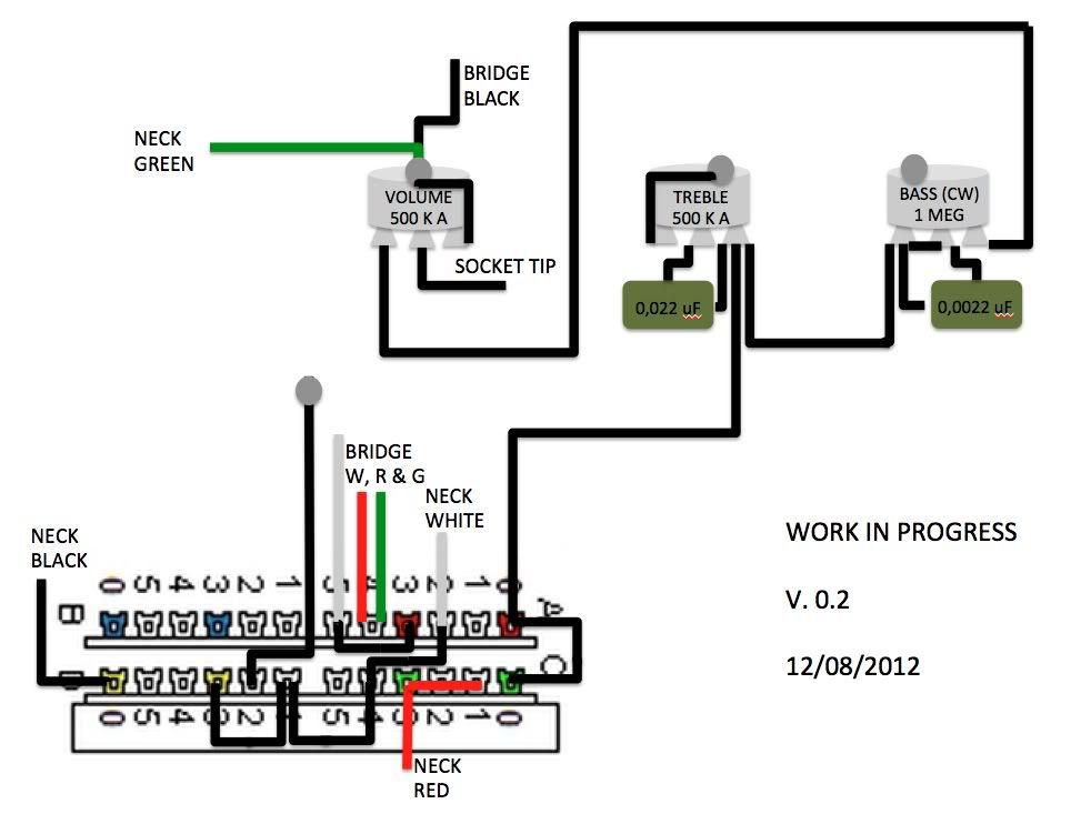 *G&L would use a reverse 1 Meg pot. And if I understand it properly that would be CCW. Is this how the bass cut should be wired if I want it CCW? 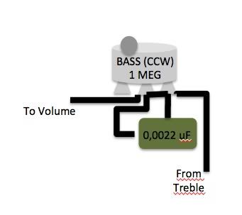 |
|
|
|
Post by newey on Aug 12, 2012 8:26:00 GMT -5
Coincidentally, I just yesterday posted the stock schematic for the G&L S-500 here. When G&l says it's a reverse pot, they mean it's a reverse audio taper pot. Any pot can be wired for CW or CCW operation, by simply swapping the wiring to the two outer lugs. If the taper is linear, then it will operate the same in either direction. If it's an audio taper pot, however, since the taper is asymmetric, the bass cut won't be right if you wire it CCW, unless you also use a reverse-taper pot. A lefty guitar (when using audio taper pots) needs reverse taper pots so that it operates in a CCW fashion the same as a righty guitar does. Same thing here if you want the bass cut to operate in reverse. |
|
Xochitl
Apprentice Shielder
Posts: 34
Likes: 0
|
Post by Xochitl on Aug 12, 2012 8:58:29 GMT -5
Thanks, newey. I had a discussion on the Guitarsbyleo forum and the other person kept telling me the previous solution wouldn't work but I failed to have in mind we were talking about an audio taper! Tell me about a dialogue of the deaf! Gosh!
I may have then two solutions:
1. look for a 1 Meg linear pot (as the curve response would be the same CW or CCW) but I'd prefer to be as close to the G&L PTB as possible.
2. look for a 1 Meg reverse audio pot and change again the wiring of the bass cut (that's the option I'd prefer).
I've been looking around the internet for a reasonable solution to source a 1 Meg audio reverse pot ("1 Meg C" ?) and the 0,0022 uF cap. The G&L online shop is not an option as the shipping charges are obscene (for Canada at least). Would someone here have some hints?
|
|
|
|
Post by ashcatlt on Aug 12, 2012 9:10:38 GMT -5
Still some issues there. The treble cut might just work, though I've never seen one wired that way before. The bass cut in the full diagram does nothing except add series resistance as the knob is turned. This should kill some treble, not what you're looking for! The bass cut at the bottom of your most recent post of pics does nothing at all.
|
|
Xochitl
Apprentice Shielder
Posts: 34
Likes: 0
|
Post by Xochitl on Aug 12, 2012 9:23:19 GMT -5
Since newey explanation, II' going back to a G&L style bass cut. Should it look like this? 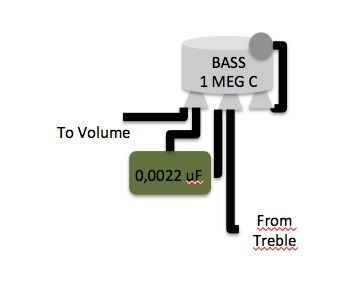 |
|
|
|
Post by newey on Aug 12, 2012 9:35:03 GMT -5
No, Xo. Look again at the G&L schematic. The cap gets wired across the pots' two outer lugs. The wiper lug (i.e., the center lug) is wired to the left-hand lug (left as shown in the schematic, I mean). The pot does not get grounded to its case, it's in series with the output.
|
|
Xochitl
Apprentice Shielder
Posts: 34
Likes: 0
|
Post by Xochitl on Aug 12, 2012 9:41:38 GMT -5
EDIT: Oops! Crossposting! Newey I'm reading your previous post and I'm coming back. Here is a new diagram where basically I use the Dimarzio schematic and try to connect the G&L PTB. 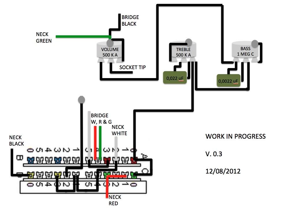 ashcatlt, the treble cut is the one used by G&L (or at leat my attempt to copy it as per the pictures linked in my first post). From those pictures, I see that the bass, treble and volume are wired in series between the switch and the jack. Is this right? newey, I knew the S-500 schematic you posted but I don't know how t translate it on a wiring diagram (as I'm still figuring out the mecanics of pots and switches). Maybe by the end of this process, I'd be a little wiser. |
|
Xochitl
Apprentice Shielder
Posts: 34
Likes: 0
|
Post by Xochitl on Aug 12, 2012 10:53:31 GMT -5
In this version, I wired the caps to the outer lugs and the wiper lugs from the treble and bass pots to their respective left lugs. But what is confusing me is that I see that in the schematics (Comanche and S-500) but not in the pictures of the actual wirings (I give that their definition could be improved). Here for the diagram: 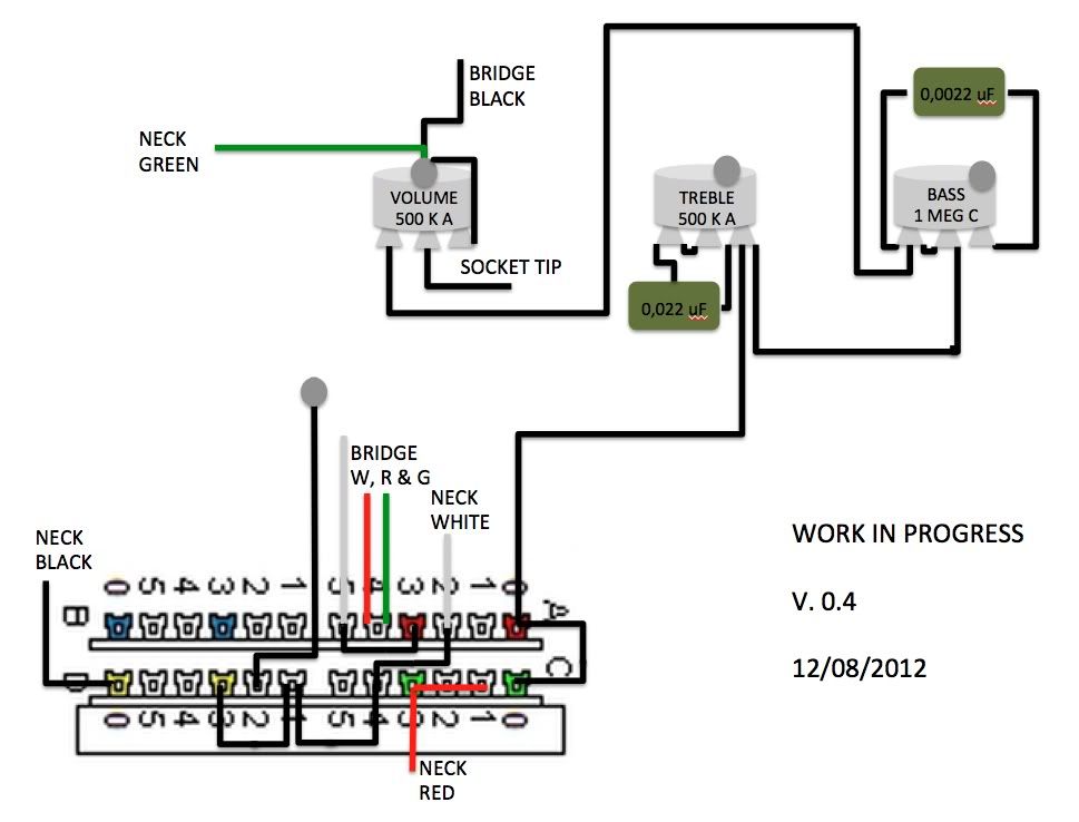 |
|
|
|
Post by ashcatlt on Aug 12, 2012 11:27:26 GMT -5
Keep going. Your bass cut is now correct for standard G&L wiring, though the previous iteration has been said to give a more dramatic response. The treble cut still ain't working. Only one end of the cap should connect to the pot.
|
|
Xochitl
Apprentice Shielder
Posts: 34
Likes: 0
|
Post by Xochitl on Aug 12, 2012 13:57:07 GMT -5
Here I'm assuming that newey (reply 11) was only about the bass control and I'm also trying to follow ashcatlt last instructions (reply 14). I stopped watching the pictures for the moment and I'm just trying to follow the advice of both of you. 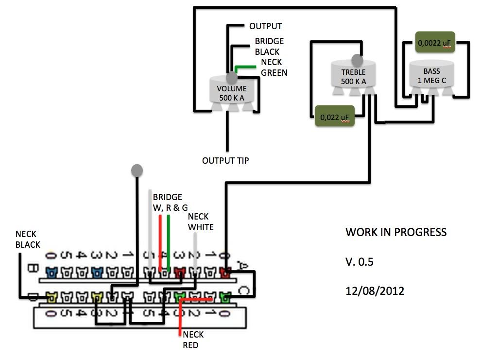 |
|
|
|
Post by newey on Aug 12, 2012 20:48:43 GMT -5
I was just talking about the bass cut. Anyway, here's a diagram based on the G&L schematic which should help to clarify things: 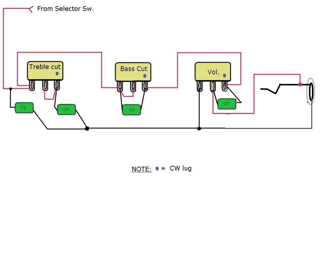 |
|
Xochitl
Apprentice Shielder
Posts: 34
Likes: 0
|
Post by Xochitl on Aug 13, 2012 7:02:05 GMT -5
Thank you, newey.  I'm going to wire C3 to the left lug of the treble cut. I'll post later a complete diagram for the record. There are some differences between what I see in the pickguard pictures and the diagram but I guess there's some room for different versions. Now it's time to order the parts and it will take some time to find and receive some of them. I believe I'll have to make some real word adaptations (the 0.0022 cap and the 1 MRA). I'll keep you posted and ask you some more questions if you don't mind. Thank you very much, newey and ashcatlt. |
|
|
|
Post by reTrEaD on Aug 13, 2012 7:50:18 GMT -5
I'll post later a complete diagram for the record. I strongly suggest posting the diagram so it can be vetted, before you do the wiring. |
|
Xochitl
Apprentice Shielder
Posts: 34
Likes: 0
|
Post by Xochitl on Aug 13, 2012 8:42:46 GMT -5
Oh shame on me. You were first to help, reTrEaD. Thank you too!
Of course I plan to post the next diagram. I'm redrawing it and I'm realizing there are more differences than I first saw. Give me a few moments and I'm putting it online.
|
|
Xochitl
Apprentice Shielder
Posts: 34
Likes: 0
|
Post by Xochitl on Aug 13, 2012 9:31:18 GMT -5
Suggestion stronly acknowledged! All the caps are here, even the treble bleed (which I may do differently in the end). 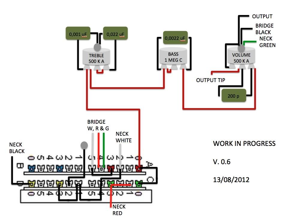 |
|
|
|
Post by newey on Aug 13, 2012 10:39:12 GMT -5
That's fine, it's equivalent. After I drew the diagram, I realized I should have shown it that way, but I forgot to make the change before posting it.
|
|
Xochitl
Apprentice Shielder
Posts: 34
Likes: 0
|
Post by Xochitl on Sept 12, 2012 15:23:20 GMT -5
I believe this was up enough time to be vetted. I just ordered the pieces a few days ago. I'll be back to report or share my noob misadventures. ;D Thanks for your help.
|
|
|
|
Post by newey on Sept 12, 2012 22:09:32 GMT -5
Let's take a look at this before you start wiring. I'm not sure it's been vetted yet.
Looking back through this thread, I had responded to what you said about the lug wiring without having seen your diagram, which you posted about an hour earlier- I probably sat on my post for a while. So I just now saw the diagram, and my last post may have buried it from view.
EDIT:OK, your diagram looks good to my eyes. Wouldn't hurt to await a second opinion, though.
|
|
col
format tables
Posts: 468
Likes: 25
|
Post by col on Sept 13, 2012 2:13:57 GMT -5
Hello, I'd like to use a 4 pole 5 way switch to achieve the following positions: 1- Neck series 2- Neck parallel 3- Neck + Bridge (parallel) 4- outside Neck + inside Bridge (parallel)5- Bridge series Is that noise canceling? Edit: Admin, I edited my post because the bold tag did not work inside the quote box (used 'size' instead). Does this always occur? Odd. |
|
|
|
Post by newey on Sept 13, 2012 8:41:41 GMT -5
It is odd, since it works for me. Did you use the button in the "add tags" area or did you type in the BBC code yourself? If you typed it, what coding did you use?
|
|
|
|
Post by reTrEaD on Sept 13, 2012 11:59:57 GMT -5
Bold doesn't work on size=1 text (the default size for quotes). It's necessary to force the size to 2 or larger if you want bold to work in a quote. Xochitl, Your diagram will work as it is right now. I have a few suggestions for improvement. Since you have an unused pole on the selector, I'd use that to disconnect the second bridge coil when it isn't needed. I think the cap in the upper left section is a bad idea. I'd eliminate it entirely. The cap in your bass cut section was selected based on a 250k volume pot. It will probably work well enough with the 500k volume, but you might choose to use a smaller value for the cap. Your treble bleed is under-compensated. Should work reasonably well, but the cap/resistor shown beneath would be a better (imho) choice. 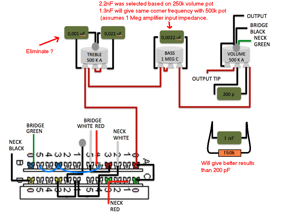
|
|
col
format tables
Posts: 468
Likes: 25
|
Post by col on Sept 13, 2012 21:18:10 GMT -5
It is odd, since it works for me. Did you use the button in the "add tags" area or did you type in the BBC code yourself? If you typed it, what coding did you use? I highlighted and clicked the bold tag button. I'm well versed in using BBC tags. I'll follow up with test post (in no one else has done so already). |
|
col
format tables
Posts: 468
Likes: 25
|
Post by col on Sept 13, 2012 21:21:29 GMT -5
Bold doesn't work on size=1 text (the default size for quotes). It's necessary to force the size to 2 or larger if you want bold to work in a quote. I guess this makes some sense. I assume browsers do not apply font-weight:bold if the font size is too small. |
|
Xochitl
Apprentice Shielder
Posts: 34
Likes: 0
|
Post by Xochitl on Sept 13, 2012 21:45:35 GMT -5
Edited to skip bold statements.
|
|