shortie87
Apprentice Shielder

Posts: 42 
Likes: 0
|
Post by shortie87 on Sept 27, 2013 7:45:28 GMT -5
Hi guys!
It's been a while, but my pickups have now arrived! However... A few posts back, I mentioned that bareknuckle suggested a reverse wound, stock polarity middle single, but you guys said this was wrong, and I ordered it RWRP as normal... And guess what bareknuckle have done... Sent it RWSP!
I've spoken to the retailer about this, and apparently, bareknuckle have told them a RWRP pickup "won't work" in my guitar.
What's the best thing I can do here? Make them take it back and send me a RWRP?
|
|
|
|
Post by JohnH on Sept 27, 2013 16:00:55 GMT -5
Hi shortie87,
Its not wrong, i think there is just a lot of confusion!
before wiring them in, or sending them back, lets check them out.
With HSH, you can always make it work with low hum, its just a matter of which coils need to be engaged in coil cut combinations, and which way round to wire each coil.
do this:
place the two humbuckers face to face, so slug poles are together and screw poles are together. Do they repell each other?
Place the middle single pup face to face with each of the slug coils of the humbuckers. Do they both attract? Thats what you want if you want to use the slug coils in the coil cut combos.
Lets start with that
J
|
|
shortie87
Apprentice Shielder
Posts: 42
Likes: 0
|
Post by shortie87 on Sept 29, 2013 15:12:24 GMT -5
Hi shortie87, Its not wrong, i think there is just a lot of confusion! before wiring them in, or sending them back, lets check them out. With HSH, you can always make it work with low hum, its just a matter of which coils need to be engaged in coil cut combinations, and which way round to wire each coil. do this: place the two humbuckers face to face, so slug poles are together and screw poles are together. Do they repell each other? Place the middle single pup face to face with each of the slug coils of the humbuckers. Do they both attract? Thats what you want if you want to use the slug coils in the coil cut combos. Lets start with that J Hi John, Sorry for the late reply, I've been away since Thursday and the pickups were at home. I've just got back and have done what you suggested. When I put the Humbuckers together so the slug coils are face to face, and they do repel each other. The Middle coil and slug coils do attract. Does this mean I should be ok with the pickups I have? If so, do I need to make any changes to my diagram? Thanks again for all your help! |
|
|
|
Post by JohnH on Sept 29, 2013 16:18:12 GMT -5
Thats great. Id say the pickups are correct for what you want. It will now come down to checking wire colours on your diagram to make sure the right coils ard selected, and in phase.
|
|
shortie87
Apprentice Shielder
Posts: 42
Likes: 0
|
Post by shortie87 on Sept 29, 2013 16:41:41 GMT -5
Phew!
The diagram is per bare knuckles colours, so unless the middle pickup needs swapped around, I think I should be good to go. On the pickups, the white and green are joined, and taped, obviously these need to be soldered to the P/P switch, but other than that i think everything is in order.
How would I check they are in phase? I'm assuming this would be pretty obvious once wired in, but I'd rather not have to solder into this switch twice...
|
|
|
|
Post by JohnH on Sept 29, 2013 16:59:25 GMT -5
Totaly a good idea!
See the screwdriver tap test ib the reference section. You need either a multimeter or wire your pickups to the sound input of your pc. Try to confirm for your self which wire pair is for the slug coil.
I haven't traced through your diagram, but going back to my sketched schematic, theres a change that would be needed. I labled coils Ns Nn etc to show coil polarity. I had these in different order at neck and bridge. For your system they need to be the same order so the coils that are connected to the main 5way switch are the same, and are the slug coils, and each pickup has the same wire pair joined. You may already have this.
|
|
shortie87
Apprentice Shielder
Posts: 42
Likes: 0
|
Post by shortie87 on Sept 29, 2013 17:31:29 GMT -5
Thanks John, I'll bring a multimeter home from work tomorrow and give that a go!
I think I already have this right in my diagram...
|
|
shortie87
Apprentice Shielder
Posts: 42
Likes: 0
|
Post by shortie87 on Sept 29, 2013 19:39:53 GMT -5
By the way, if they're out of phase, what do I do?
EDIT: Quick google search and engaging my brain for 5 minutes explains that this is the reason for swapping around the hot and ground on the middle... I'm assuming that if this is how BKP send out their pickups, that I should just be able to wire it up as expected and all should be right, but I'll check anyways if I can, if not, I guess its only the middle i'll need to solder twice!
Hopefully, I'll be all done tomorrow night, I'll let you all know how I get on!
|
|
shortie87
Apprentice Shielder
Posts: 42
Likes: 0
|
Post by shortie87 on Dec 10, 2013 19:07:46 GMT -5
Hi all,
Sorry I've not been back to give you any updates on this, I've been very busy lately following a job promotion, so I'm just getting around to looking at this again!
I managed to get the guitar wired up as per the diagram (although I'm sure I made some mistakes with the DPDT switches, never done these before) but it didn't work anywhere close to how it was supposed to. I had to strip the lot out again, and I've just dropped the new pickups in the old wiring. They sound great! One thing I have noticed though is that the middle pickup seems to be out of phase with the humbuckers. At least I know this now for attempt number 2... so I need to swap the hot and ground on the middle next time...?
I've bought some new pots again, as the Push/Pulls aren't going to work. I didn't realise originally that the cavity in my guitar is quite shallow, so they didn't fit properly, and I really don't want to have to remove any wood from the guitar, so I think I'm going to try with some sliding, ON - ON switches. I'm thinking these should work in the same way as the ones already in the diagram?
Thanks all,
Martyn
EDIT: On a side note, I've very happy to simplify this now to get things going. I'd still like one switch to do the coil tap/split on both pickups at the same time, however I'm not all too bothered about the middle pickup on/off in P3 thing... |
|
|
|
Post by newey on Dec 10, 2013 23:36:49 GMT -5
They will need to be double pole switches. There are various types of slide switches, some have 8 lugs instead of 6. The 8 luggers will work the same as the 6-lugged ones if you connect the 2 center lugs together on each side of the switch.
|
|
shortie87
Apprentice Shielder
Posts: 42
Likes: 0
|
Post by shortie87 on Dec 16, 2013 11:58:38 GMT -5
Hi Newey,
I've ordered some ON/ON mini toggles, but when they've arrived, I've been sent ON/OFF/ON switches instead. They have 6 lugs, and we're advertised as DPDT. Could I use these or would they not really work? I'm thinking I could use one side for 'normal' mode, the other side for 'coil split' mode, and the Middle to kill the signal completely?
|
|
|
|
Post by newey on Dec 16, 2013 14:41:52 GMT -5
shortie-
You can potentially use those switches if you can live with redundancies in your switching. It may be possible to have an 'off" position if you want that, I'll need to take a closer look. What would be easily do-able with an on-off-on switch would be to have the coil cut setting with the switch flipped to one side, and then both the center and the other side would give you, not "off", but the full HB in either position (that's the redundancy).
There will need to be some changes to the diagram, however.
But before we zero in on the changes, please post the final diagram you are using. This thread has run to several pages now, and there have been a number of different diagrams. I want to be sure what you're using to wire from before I suggest further changes.
|
|
shortie87
Apprentice Shielder
Posts: 42
Likes: 0
|
Post by shortie87 on Dec 16, 2013 17:11:12 GMT -5
Hi Newey,
I'm going to go with the diagram I've taken from the Dimarzio site, its slightly less complicated to figure out, and doesn't require as much in the way of switching, plus I only lose one position I wanted, and I can live with that.
This is using the Dimarzio colour code, I can change this to suit later. I realise the diagram isn't great (in that its all black and white) but the PC I have that runs Visio is currently out of action...
Thanks for all your help, not to mention patience!
|
|
|
|
Post by newey on Dec 16, 2013 23:00:47 GMT -5
You aren't kidding- that's pretty much unreadable! It will probably be a few days before I can get a chance to read through that.
But this scheme has only one p/p, not the two we discussed earlier- and that one switch isn't just cutting a coil off the HBs, it's acting as a mode switch for the 5-way. So ignore everything I said earlier, I'm not sure what we're looking at with this scheme.
|
|
shortie87
Apprentice Shielder
Posts: 42
Likes: 0
|
Post by shortie87 on Dec 17, 2013 14:07:24 GMT -5
I've redrawn this with some colour, so hopefully this makes it a bit clearer! 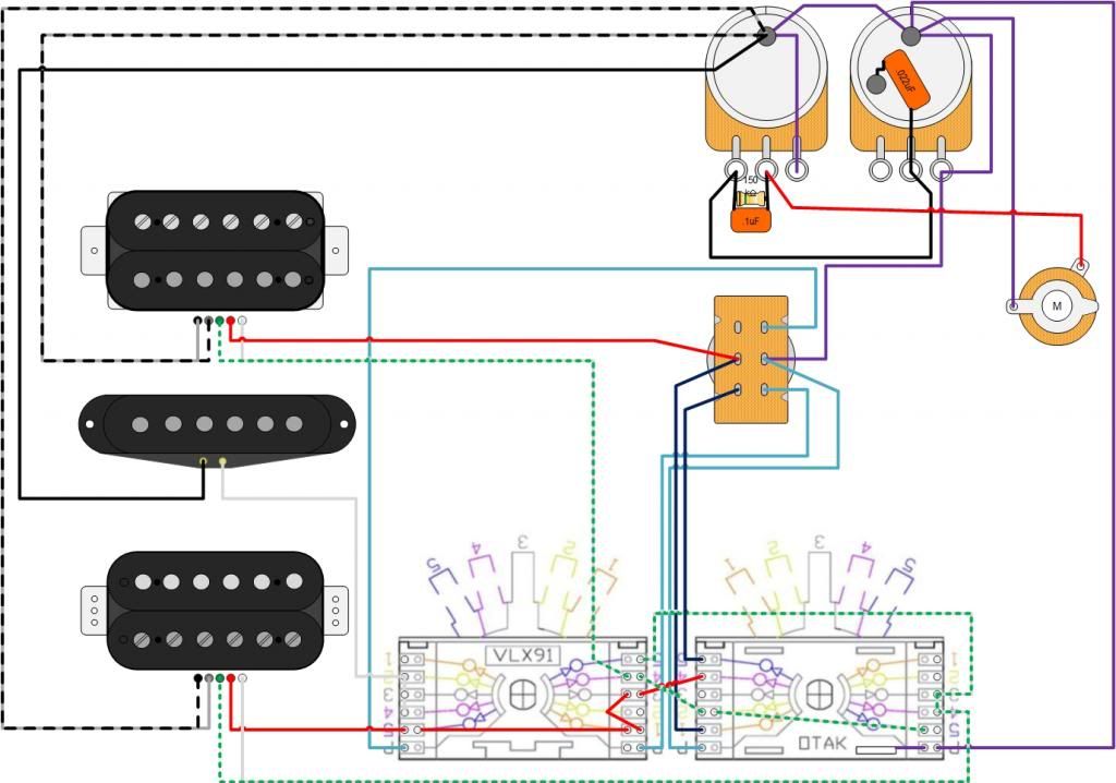 |
|
shortie87
Apprentice Shielder
Posts: 42
Likes: 0
|
Post by shortie87 on Dec 18, 2013 17:24:32 GMT -5
Ok, so...
I've spoken to the guy I got the switch from, he's sent me the wrong one and is sending out an on/on which I should have in the next few days.
When this arrives, should I be ok to go with the diagram?
|
|
|
|
Post by newey on Dec 18, 2013 23:51:37 GMT -5
Well, if you took it straight from the DiMarzio site it ought to be OK. But I'm having trouble figuring out what this is doing. Maybe we can get another set of eyes?  |
|


