|
|
Post by newey on Jun 14, 2020 7:26:49 GMT -5
Yogi B- I missed the "u"s and "d"s, very helpful. But very slow going to vet this, so far I have verified position 5 after about 20 minutes! Stay tuned . . .
|
|
cem
Meter Reader 1st Class

Posts: 99
Likes: 0
|
Post by cem on Jun 14, 2020 10:16:05 GMT -5
Yogi B, after newey gets this vetted, you could also add the 1 meg resistor across the tone cap on the TBX pot that Phostenix uses to reduce the popping sound that occurs when going to or from the no load center position. You can see it in his "Wiring Diagram for the Modified TBX Tone Control". But he never puts it in his guitar wiring diagrams for some reason.
|
|
|
|
Post by newey on Jun 14, 2020 20:27:20 GMT -5
cem: I've spent a good deal of time trying to make sense of this scheme, and I'll admit I'm floundering, I just can't wrap my mind around this scheme. You should know that YogiB is usually right about these things, but someone else is going to have to verify this, it's beyond me. 
|
|
cem
Meter Reader 1st Class
Posts: 99
Likes: 0
|
Post by cem on Jun 15, 2020 18:02:23 GMT -5
cem : I've spent a good deal of time trying to make sense of this scheme, and I'll admit I'm floundering, I just can't wrap my mind around this scheme. You should know that YogiB is usually right about these things, but someone else is going to have to verify this, it's beyond me. No problem newey. I'm sure you did your best so thank you very much. Anyone else who can help with vetting this? |
|
|
|
Post by newey on Jun 16, 2020 13:02:18 GMT -5
We need diagram help on aisle 7! Anyone care to help cem out (given that I have failed)? reTrEaD? sumgai? JohnH? |
|
|
|
Post by Yogi B on Jun 16, 2020 23:16:53 GMT -5
you could also add the 1 meg resistor across the tone cap on the TBX pot that Phostenix uses to reduce the popping sound that occurs when going to or from the no load center position. . We need diagram help on aisle 7! Anyone care to help cem out (given that I have failed)? reTrEaD? sumgai? JohnH? Can I tempt anyone with an equivalent schematic? |
|
|
|
Post by sumgai on Jun 17, 2020 15:29:50 GMT -5
Lunch times is about up, so I'll look at Yogi's latest schematic tonight, instead of vegging out in front of the 'tube.  EDIT EDIT: It's later, and I've finished the review. If the schematic is the direct equivalent of the wiring layout, then it should work like it says on the tin.  (Of course, I'm referring to Yogi's truth table within the schematic.) HTH sumgai |
|
cem
Meter Reader 1st Class
Posts: 99
Likes: 0
|
Post by cem on Jun 19, 2020 2:49:58 GMT -5
Just one more week to go. Can't wait to play the best strat in the universe:)
In the meantime i would like to ask something about the tbx pot.
Has anyone used a modded tbx pot for a long time? Did the silver conductive paint come off after months of use? Is there a way to prevent it from happening?
I don't even understand what the paint does. How do i know if it comes off? Would the tone of the guitar change?
|
|
|
|
Post by frets on Jun 19, 2020 8:09:15 GMT -5
Hi Cem,
It’s wonderful that you’re so close to having your dream realized.
I’ve worked with several TBX’s and have experienced the slight flaking of the finish surface. It does not affect the pot function. It’s just annoying. A photo would be great if possible so that the members can see it. I have used clear acrylic nail polish on the flaked areas to inhibit further flaking on the case.
|
|
|
|
Post by Yogi B on Jun 19, 2020 23:48:24 GMT -5
I’ve worked with several TBX’s and have experienced the slight flaking of the finish surface. It does not affect the pot function. It’s just annoying. A photo would be great if possible so that the members can see it. I have used clear acrylic nail polish on the flaked areas to inhibit further flaking on the case. is referring to the application of conductive paint to the resistive trace of the potentiometer as in Phostenix's guide: Has anyone used a modded tbx pot for a long time? Did the silver conductive paint come off after months of use? Is there a way to prevent it from happening? I forgot that conductive paint was part of Phostenix's modded TBX.The paint is there to ensure the that at the centre-detent position the bass-cutting series capacitor is completely bypassed. If the conductive paint is omitted there will instead be some small resistance in parallel with the guitar signal (and in parallel with that capacitor)You probably wouldn't notice, because the change in tone would be imperceptive. Even with the assumed unmodded resistance of 1k as in Phostenix's video that would result in a reduction of only about a quarter decibel at the resonant peak. Furthermore, even if all the conductive paint wears off from underneath where the wiper makes contact, some paint will remain at the outer edges of the track. This remaining paint should still be enough to keep the resistance at the centre position to no more than a few ohms. |
|
cem
Meter Reader 1st Class
Posts: 99
Likes: 0
|
Post by cem on Jul 3, 2020 14:58:33 GMT -5
Hello everyone.
It's been a while but i am very close to verifying this diagram. I've got my guitar back but there are some problems we need to solve.
Most of the wiring works and i am very pleased with it! (On a side note Fender's 57/62 pickups are amazing for how cheap they are.)
So the issues i have are:
1- On strat mode, on positions 4 and 2 the blend pot does not work. So i can't get all 3 pickups at once. Other positions work as they should.
2- On series mode, positions 5 and 4 are the same with each other, n and m in series. And positions 1 and 2 are the same with each other as well, b and m in series. Everything else, including the blend pot work as they should on this mode.
So i don't think this is too hard of a problem to solve because it's only the 2nd and 4th positions causing issues on both modes. Probably my tech just overlooked some tiny detail?
Any help would be appreciated:)
By the way, i don't know if this is supposed to happen or maybe this is part of the problem but there are some dead zones in between positions on the 5 way switch. What i mean by that is, when for example, switching from 5th to 4th position on strat mode you almost get a click sound when playing and if you keep the switch right in the middle of 5th and 4th positions it's completely dead silent. This is not bothering me too much because it is almost imperceptible if you are not trying to hear it but it's there.
It occurs in between 5th and 4th, 1st and 2nd positions on strat mode and only in between 2nd and 3rd positions on series mode.
Is that normal or maybe part of the problem?
|
|
|
|
Post by Yogi B on Jul 4, 2020 6:14:11 GMT -5
1- On strat mode, on positions 4 and 2 the blend pot does not work. So i can't get all 3 pickups at once. Other positions work as they should. 2- On series mode, positions 5 and 4 are the same with each other, n and m in series. And positions 1 and 2 are the same with each other as well, b and m in series. Everything else, including the blend pot work as they should on this mode. So i don't think this is too hard of a problem to solve because it's only the 2nd and 4th positions causing issues on both modes. Both of those issues would be caused by omission of the connections performed by the left-most (as my diagram shows it) terminals of the S1 switch. The smallest possible error is that the (cyan/turquoise) wire connecting the centre terminal to the position 2 terminal of the (lower left) neck negative pole of the superswitch is missing. (The adjoining wire from that terminal to the position 4 terminal of the (lower right) bridge positive pole may or may not also be missing.) If that wire is missing, then the adjacent (fuchsia/pink) wire connecting the upper terminal to the position 1 terminal of the (lower left) neck negative pole of the superswitch could also be missing. (From positions 1 & 5 working as intended we know that the rest of this wire, over to the position 5 terminal of the (lower right) bridge positive pole and to the blend pot, is present and correct). Alternatively, the (blue) wire connecting the remaining lower terminal of the left-hand side of the S1 switch to the other terminals on the S1 itself could also be missing, though this is unlikely since the other connection that the (blue) wires make between the top and right poles of the S1 must be present, in order to get any output in series mode positions 2 & 4. If the cyan/turquoise wire is not missing, then both the above mentioned fuchsia/pink wire and the blue wire must be missing. Well it wasn't intentional, truth be told I didn't put a lot of thought into what happens between positions, but it is a normal feature of the 'correct' wiring. The annoying thing is that now you've brought my attention to it, I reckon it could be fixed. |
|
|
|
Post by newey on Jul 4, 2020 7:47:47 GMT -5
he cyan/turquoise wire is not missing, then both the above mentioned fuchsia/pink wire and the blue wire must be missing Just so we're clear, when YogiB says "the wires are missing", the wires may be present but not properly connected at one end or the other. |
|
cem
Meter Reader 1st Class
Posts: 99
Likes: 0
|
Post by cem on Jul 4, 2020 17:01:18 GMT -5
Allrighty. Sounds easy to fix. I will probably leave the guitar like this until i get a middle pickup that is RWRP though, which will take 2 months tops. Sorry  I would love it if you could fix it though. |
|
|
|
Post by Yogi B on Jul 18, 2020 22:41:23 GMT -5
Sorry I would love it if you could fix it though. Sorry it took so long, but here's what should be fixed version: To narrow down where to look for the changes between this and the previous version: they are located on superswitch poles connected to the leads of the middle pickup, i.e the upper pair in the wiring diagram, which (appropriately enough) correspond to the middle pair in the schematic. |
|
cem
Meter Reader 1st Class
Posts: 99
Likes: 0
|
Post by cem on Jul 19, 2020 14:26:52 GMT -5
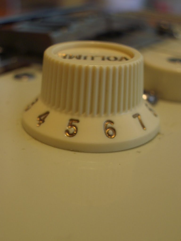
Thank you so much Yogi B! I will probably get it done at the end of August. I can't wait! I am quite impressed with the wiring already by the way. The series mode is really useful. I wonder what the 2nd and 4th positions sound like. The only problem i have right now is the s-1 switch looks wierd. When it's not pushed down it looks like it's pushed down. And when it is pushed down it goes way lower then it should. Have you guys ever come across this problem? Could this be caused by the cap or the knob or the switch itself? If it's the cap or knob, i will change it someday but if not i'm gonna have to suppress my OCD since the s-1 switch is a bit too pricey lol. |
|
|
|
Post by Yogi B on Jul 20, 2020 0:41:14 GMT -5
The only problem i have right now is the s-1 switch looks wierd. When it's not pushed down it looks like it's pushed down. And when it is pushed down it goes way lower then it should. Have you guys ever come across this problem? Could this be caused by the cap or the knob or the switch itself? If it's the cap or knob, i will change it someday but if not i'm gonna have to suppress my OCD since the s-1 switch is a bit too pricey lol. I suppose the first question is whether this is a Strat or Tele style S-1 switch. I know this thread is all about a variation on the Strat wiring and going into a Strat guitar, but that doesn't mean that your definitely using the Strat version -- some people do prefer Tele knobs on a Strat. But for now I am going to assume it is the Strat version. I can't really imagine much that could be wrong, as the pot/switch, knob, and cap are all designed to fit together without much room for height adjustment. There's only two possibilities I can think of: - Perhaps it is not that the cap is too low but that the knob is too high, maybe it is not pushed on all the way. How far is the knob off the pickguard? Will it move any further down or is it already touching the pickguard? If the latter then maybe the entire pot is sitting to low and that is preventing the knob from being pushed on further, to its proper location (for example if a too thick washer or just too many washers were used between the pot and the underside of the pickguard).
- Alternatively it may be that the cap is damaged. As far as I recall the part of the Strat cap that mates with the push-switch's actuator is a fully hollow tube and what prevents it from being pushed too far down the actuator is that the diameter of the actuator increases. However this increase is only slight, therefore with excessive force it could be possible to force the cap further down onto the thicker section, potentially splitting or otherwise permanently deforming the tube in the process.
|
|
|
|
cem
Meter Reader 1st Class
Posts: 99
Likes: 0
|
Post by cem on Jul 23, 2020 3:22:57 GMT -5
I think i was able to post images. Can you guys see them in my last post?
|
|
|
|
Post by JohnH on Jul 23, 2020 6:08:28 GMT -5
sure I can see the photos
|
|
|
|
Post by newey on Jul 23, 2020 7:59:36 GMT -5
The nut on top of the washer is the normal way to mount a pot. Often, there is a second nut underneath the pickguard to set the height.
In your case, it looks as if the pot is sitting a bit cocked-over, since it looks to have, as you say, about a 2mm gap on one side but looks flush on the other. This could be either because the pot is not fully seated flush throught the hole, or becuase something underneath the pot is jacking the pot upwards, along with the pickguard at that point.
My strong suspicion is this: Does your pot have a locating tab? Usually, these need to be removed for guitar use. The tab is designed to keep the entire pot from turning in its mounting when mounted to a metal control panel- the panel has a corresponding slot into which the locating tab fits. Since there is no slot in the pickguard, the tab interferes with flush-mounting the pot. Again, just a guess on my part.
|
|
|
|
Post by newey on Jul 23, 2020 8:06:45 GMT -5
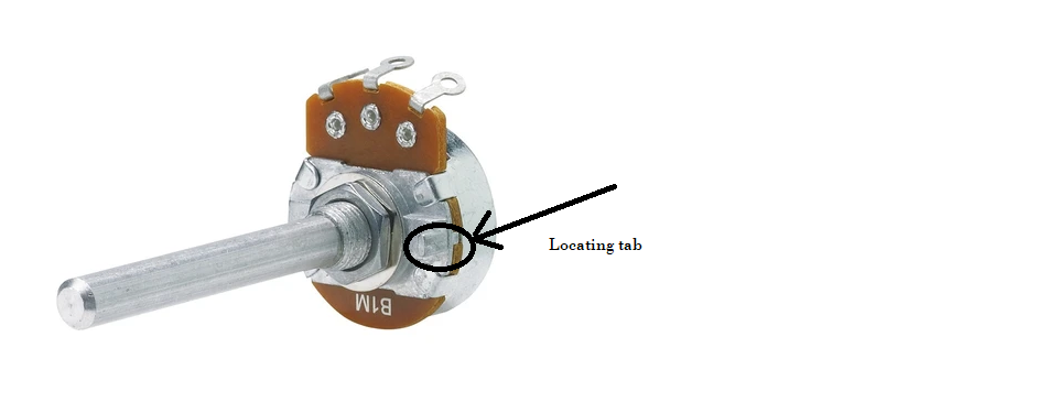 Here's an example of what I'm talking about. You can use a needle-nosed pliers to bend the tab back and forth a few times and it will snap off. |
|
cem
Meter Reader 1st Class
Posts: 99
Likes: 0
|
Post by cem on Jul 24, 2020 18:41:32 GMT -5
Ok. I will look out for that locating tab. But if that isn't what's causing the problem it looks like i will be able to solve it like this: wackerman.blogspot.com/2010/10/fender-s-1-switch-looks-engaged-when-it.htmlThis was hard to find. So this guy installed a thinner, regular looking washer instead of the one with teeth, underneth the pickguard. This weird looking washer is a bit too thick apparently. With a thinner one the s-1 sits higher thus solving the problem. Would changing that part present any downsides? Those teeth look like they are there for something. What is their use? |
|
|
|
Post by Yogi B on Jul 25, 2020 3:07:38 GMT -5
It seems like the knob is too high. There is a 2mm gap between it and the pickguard. I can't press it down though no matter how hard i push. The fact that there is a gap suggests that the pot itself isn't sitting too low. If the pot were to low then I'd expect the knob to be basically touching the pickguard, like in the article you linked: So this guy installed a thinner, regular looking washer instead of the one with teeth, underneath the pickguard. This weird looking washer is a bit too thick apparently. With a thinner one the s-1 sits higher thus solving the problem. Would changing that part present any downsides? Those teeth look like they are there for something. What is their use? As above, I don't think this is the root of the problem in your case. But to answer your questions, it is a type of lockwasher, designed to reduce to likelihood of the fixing nut from loosening from normal use. The teeth are there to bite into the mounting material in order to give better rotation resistance (and better electrical conductivity, if applicable). For the most part I'm personally not a fan of them, I'd rather not have them bite into my pickguards or into the bare wood on rear-routed guitars, but I'm fine with them if they're going into metal e.g. a metal jack plate or a Tele control plate where they won't chew up the surface. As such I generally don't use them with wood or plastic and short/medium length shaft pots because I'd want to use them in combination with a regular washer to protect the pickguard or guitar body, and that usually ends up adding too much thickness. Without them I don't find that my controls come loose, but if I did I'd look for a less aggressive type of lockwasher e.g. a crinkle washer or a split/spring washer. The only place I know I've definitely used a toothed/serrated lockwasher in conjunction with wood is in my Tokai LP copy. It does just about accept medium shaft pots, but that means the bell knobs are too low to easily grab underneath them in order to pull the push-pulls, hence why I went with long-shaft. That means there is plenty of room on the inside portion of the shaft, so the extra thickness of a serrated lockwasher is no issue. If I remember correctly the stack goes: pot body, gap, nut, grounding washer, nut, lockwasher, washer, guitar top wood, washer, pointer washer, nut, knob. |
|
cem
Meter Reader 1st Class
Posts: 99
Likes: 0
|
Post by cem on Aug 28, 2020 19:30:59 GMT -5
Hello people. My friend who also worked as a guitar tech years ago came to where i live recently. He tried to fix the wiring. I forgot to check if the dropout problem was gone but 3 pups in parallel and 2nd and 4th position with s1 switch pushed in still didn't work. It was exactly the same as before. I too have checked every wire and everything looked just like how it shows in the latest diagram. He told me to leave the guitar with him so that he could start from scratch. He just called me to let me know that the result is the same. So 2 different people wired the guitar and the outcome is exactly the same which leads me to believe that there is something wrong with the diagram. So if you guys could check the wiring again or come up with a solution it would be awesome. Yogi B senpai help me pls As a side note i can't convince anyone to modify the pot for no-load. They think they will ruin the pot. My friend said the mod looked easy to do in the video i had showed him but this one could be more complicated because this is a push-pull pot. Would this make it any harder than modding a regular pot? I could not find a single video showing the mod on a push-pull. If there is one somewhere, it would be awesome if i could get a link of it. As always, thank you guys so much for doing gods work:) |
|
|
|
Post by Yogi B on Sept 4, 2020 9:11:41 GMT -5
So 2 different people wired the guitar and the outcome is exactly the same which leads me to believe that there is something wrong with the diagram. So if you guys could check the wiring again or come up with a solution it would be awesome. Yogi B senpai help me pls Well I've double (and triple) checked it, but neither me, nor the program I've written to help debug wiring can see that there is anything wrong with my diagram/schematic, so I'm pretty confident in it, but I could still be missing something. "Your eyes are best used looking at a meter", or words to that effect -- you might not necessarily see a cold solder joint, a solder bridge, a tin whisker, a wire broken within its insulation, or a faulty switch. While continuity tests with an ohmmeter/multimeter won't help identify the cause of the issue, they will determine whether there is an issue. As noted in my previous message the problems you report seem to indicate a missing connection to the left (as laid-out on my diagram) three terminals of the S1 switch (the pole with the pink, cyan, and dark blue wires connected). Therefore I'd focus continuity tests in that area, checking continuity directly across the terminals of the S1 switch in both up/down positions and working outwards from there Overall disassembling a push/pull pot is not all that different to disassembling a regular pot, the only real catch is the literal catch that attaches the pot shaft to the switch mechanism. With pot in the pulled position, after lifting the metal tabs such than the bushing, wafer and wiper are all loose, the whole assembly must be slid a short distance horizontally backwards (away from the front, where the terminals are located). This is easier if done upside-down such that the loose parts slide along the shaft towards the knurled end, thereby allowing the other end of the shaft to move more freely. I can't find a good video or specifically this, but here is a video showing the attachment between the shaft and the switch from someone reassembling the switch proportion of a push-pull (to be clear, this is just for illustration purposes, in your case the switch portion need not be disassembled). On the subject of ruining the pot, one thing to be careful of with push-pulls & other 'mini' pots is that you don't use to much pressure when bending the tabs back over the bushing during reassembly, as I have previously managed to snap the wafer by doing this. (I can't remember how exactly, though I may have been using something completely over the top, like mole grips) |
|
cem
Meter Reader 1st Class
Posts: 99
Likes: 0
|
Post by cem on Oct 3, 2020 12:16:54 GMT -5
Hello fellas. It's been a long journey. But now i know what went wrong. Since the same thing happened twice i wanted to go with another diagram. I didn't like mixing parallel and series sounds because it felt like they didn't have enough character so chose this diagram which is much cleaner: guitarnuts2.proboards.com/thread/8447/parallel-series-stratocaster-easy-soundsA similar problem occured, the 2nd position wasn't working as far as i can remember. It turns out the s1 switch was causing the problem. My friend soldered 3 little dots in the middle of the switch which are 12 in total. And voila, the problem was solved. So if it wasn't for the s1 switch Yogi B 's diagram would have worked. I'm happy with Carlos Sanz 's diagram though. But this gave me an idea for my future project which is a nashville tele. Can we change Carlos's diagram and make the 3rd position N+B instead of just middle? Thanks sooo much!!! |
|
|
|
Post by newey on Oct 4, 2020 7:51:23 GMT -5
Can we change Carlos's diagram and make the 3rd position N+B instead of just middle Since Carlos' diagram uses a 4 pole Superswitch, yes, it could be done. However, he uses a "neck on" switch on the tone control, so his scheme already offers N + B (just not at position 3 of the lever switch). So, you'd have some redundancy in the switching, but it could be done if desired. |
|
cem
Meter Reader 1st Class
Posts: 99
Likes: 0
|
Post by cem on Oct 4, 2020 8:08:29 GMT -5
Can we change Carlos's diagram and make the 3rd position N+B instead of just middle Since Carlos' diagram uses a 4 pole Superswitch, yes, it could be done. However, he uses a "neck on" switch on the tone control, so his scheme already offers N + B (just not at position 3 of the lever switch). So, you'd have some redundancy in the switching, but it could be done if desired. Awesome!! I want to get rid of the neck on switch. I forgot to mention that. I dont want to use a push pull pot to get N+B on a tele. Also when the s1 switch is down it should become NxB. |
|


 (Of course, I'm referring to Yogi's truth table within the schematic.)
 I would love it if you could fix it though.