|
|
Post by angelodp on Nov 20, 2020 18:22:31 GMT -5
Hi, trying to figure out a way to do a NFB foot switch for an amp I am tweaking. The tube amp is in the 5C3 realm. The NFB loop is from the cathode of V3 (6SL7) through a 36k resistor to the 16ohm tap. I have a simple spst switch which is either NFB on or off. I would like to keep the functionality of the panel switch and add a jack to foot pedal switch into the mix. With the foot pedal I can see a way to have both the panel switch and foot switch working interchangeably, but once the foot switch is removed the connection to the NFB is also removed. & NFB, I would like to not use a relay to do this. 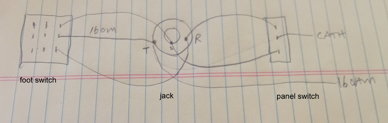 |
|
|
|
Post by sumgai on Nov 21, 2020 10:49:28 GMT -5
ange, Are you using an insulated jack? If not, then one side of the switch is always going to ground (via the Sleeve terminal), whether or not the plug is inserted. Removing the plug shouldn't affect this, but if the jack is not insulated, then who knows.....  Also, is this a switching jack of any kind, or is it a bog-standard TRS jobbie? A switching jack might also contribute to your problem. HTH sumgai |
|
|
|
Post by thetragichero on Nov 21, 2020 14:59:31 GMT -5
I've been following this on the amp garage forum and right now it's still in the planning stages.
what a novel idea, figuring out how to make it work before plugging the iron in 🙃
|
|
|
|
Post by reTrEaD on Nov 21, 2020 15:04:13 GMT -5
Hi angelodpThis is how you would wire the jack and switch on the amp to allow for switching the NFB on or off. It requires a TRS jack which has a switch built-in and a SPDT mini-toggle. 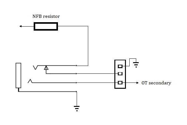 The switch on the jack disconnects the NFB resistor from the pole of the SPDT when the footswitch is plugged-in. I'm sure you can draw up the footswitch with the pole of the switch connected to the tip of the plug, one throw connected to the sleeve, the other throw connected to the ring. |
|
|
|
Post by sumgai on Nov 21, 2020 15:46:22 GMT -5
reTrEaD,
In ange's OP, he states that he'd like to have both switches functional at the same time, should the footswitch be plugged in as well. Your method disconnects the panel switch, so it becomes a footswitch only setup.
My question is, what happens when the feedback resistor is grounded, instead of going to the OT secondary? I'd like to see the pertinent portion of the schematic where this will be attached, if someone will please make it so. (And no, I'm not going to look at a 5C3 diagram, because this amp is purported to be based on it, and not an exact copy.)
sumgai
|
|
|
|
Post by angelodp on Nov 21, 2020 16:50:51 GMT -5
Hi, yes I would like to make this work so that either the panel switch or the foot switch can toggle the effect, whether the foot switch is inserted (with a jack) or not. I could use an isolated jack and, I should think that the NFB R is never grounded. The Cliff 6 pin switched jack might be the ticket. Just trying to wrap my no-engineering head around the correct wiring. The cathode connection from the 3rd gain stage (6Sl7) goes through a 36k resistor and onto the 16ohm tap. 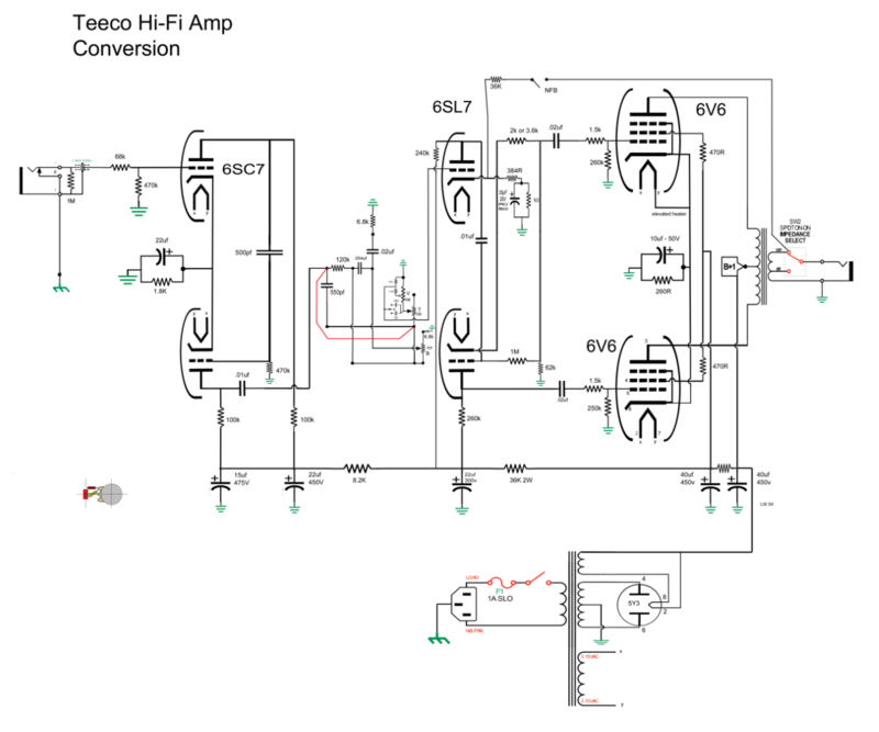 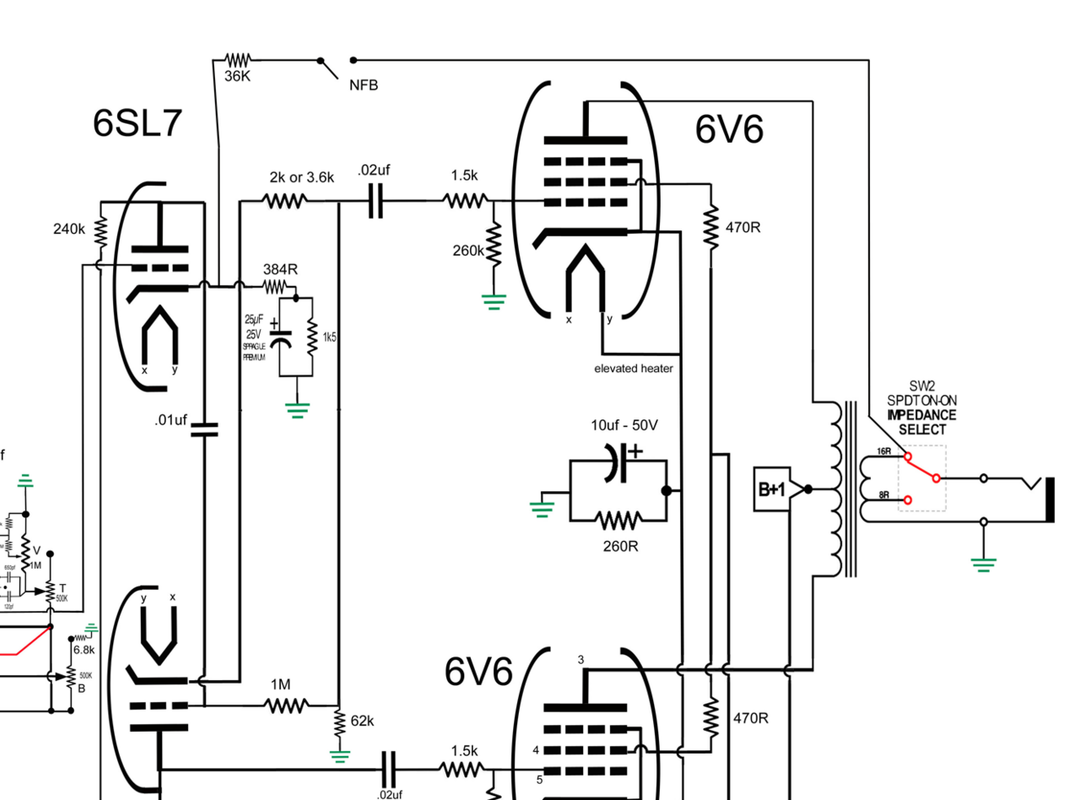 |
|
|
|
Post by sumgai on Nov 21, 2020 19:00:05 GMT -5
ange, Looking at this as I eat a late lunch, but can't spend much time on it - daylight is in short supply around these parts!  I'll get back on it later tonight, but for sure, grounding that 36KΩ resistor will have a deleterious effect on your sound... not to mention on your tubes as well. In effect, it would short the bias supply to the cathode of the upper half of the tube, and pretty much cut off the signal, or at least send it into a non-linear region of operation. That latter part is the provender of what we call "distortion". Ugly. And potentially harmful to the tube's life, over the long run. Stay tuned. (Unless reTrEaD posts an updated version before I get back.  ) sumgai |
|
|
|
Post by reTrEaD on Nov 21, 2020 20:39:23 GMT -5
I'll get back on it later tonight, but for sure, grounding that 36KΩ resistor will have a deleterious effect on your sound... not to mention on your tubes as well. In effect, it would short the bias supply to the cathode of the upper half of the tube, and pretty much cut off the signal, or at least send it into a non-linear region of operation. That latter part is the provender of what we call "distortion". Ugly. And potentially harmful to the tube's life, over the long run. That's an interesting alarmist tale but it's utterly and completely WRONG. Please look at the drawing I posted. The end of the 36k that's normally connected to the 16ohm secondary of the OT, is the end that's being connected to ground when the NFB is removed. Then do the math. The DC resistance from cathode to ground is: The series resistance of the 384 ohm resistor plus the 1.5k resistor. (That's 1884 ohms.) In parallel with ...The 36k NFB resistor plus 16 ohms (or likely less) for the 16ohm secondary of the OT. (That's 36016 ohm or less) That calculates out to 1790.35 ohms If we instead, connect that end of the 36k resistor directly to ground, that gives us 36k. In parallel with the 1884 ohms, That calculates out to 1790.31 ohms So Sparky, would you care to explain how a 0.0022342499344% reduction in cathode resistance will cause the horrendous problems you claim? Stay tuned. (Unless reTrEaD posts an updated version before I get back. Not a chance of me stealing the limelight from you on this one. Take all the time you need.  |
|
|
|
Post by JohnH on Nov 21, 2020 22:57:23 GMT -5
Im not across all the issues on this. But is there any problem to worry about in terms of just the basic idea of taking such a signal out of the amp down to a remote switch then bringing it back again? I'm wondering about such things as interference, stability, noise etc.
|
|
|
|
Post by angelodp on Nov 21, 2020 23:23:50 GMT -5
I tried it with a mock up, where the footpedal takes over, and it works with no noise. I just have not tried the dual switch setup.
|
|
|
|
Post by JohnH on Nov 21, 2020 23:35:53 GMT -5
ok good, Best to check such things!
|
|
|
|
Post by angelodp on Nov 21, 2020 23:57:06 GMT -5
Hi angelodpThis is how you would wire the jack and switch on the amp to allow for switching the NFB on or off. It requires a TRS jack which has a switch built-in and a SPDT mini-toggle. The switch on the jack disconnects the NFB resistor from the pole of the SPDT when the footswitch is plugged-in. I'm sure you can draw up the footswitch with the pole of the switch connected to the tip of the plug, one throw connected to the sleeve, the other throw connected to the ring. Are you suggesting that the jack here is isolated? |
|
|
|
Post by angelodp on Nov 22, 2020 0:24:20 GMT -5
Switchcraft 13B - like this? 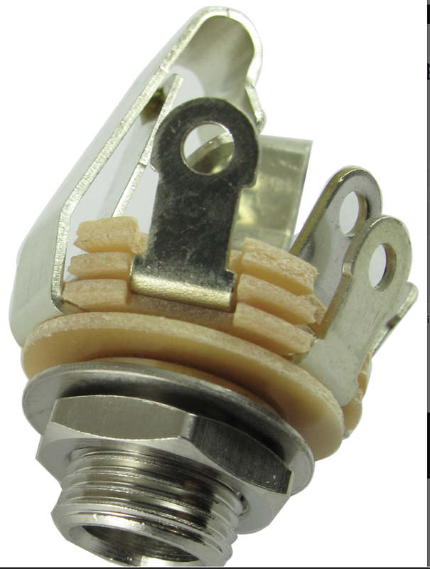 |
|
|
|
Post by reTrEaD on Nov 22, 2020 10:52:26 GMT -5
Im not across all the issues on this. But is there any problem to worry about in terms of just the basic idea of taking such a signal out of the amp down to a remote switch then bringing it back again? I'm wondering about such things as interference, stability, noise etc. Always a consideration. In this case there isn't a ton of gain from the cathode of the 6SL7 to the output of the circuit but enough to be a problem, except that the input impedance is moderately low and also the impedance at the other end of the NFB resistor is very low. 16 ohms when driven by the secondary of the OT. Lower than that when connected to ground. External hum and noise won't have much 'torque' against these low impedances. For sure they will have some effect but unlikely to be enough mention. I did notice the 6SL7 below is connected in a paraphase configuration. That's a rather archaic design. Not sure why anyone would choose to go there rather than use a long-tailed pair for those two 6SL7s. |
|
|
|
Post by reTrEaD on Nov 22, 2020 10:58:00 GMT -5
Are you suggesting that the jack here is isolated? Nope. Switchcraft 13B - like this? That would be just fine for what I drew. But you might want to wait to see what sumgai comes up with and what sort of jack it requires. Maybe his solution will allow the footswitch to toggle the action of the panel switch. Mine doesn't. Oh and another question ... Why are you averse to using a relay? |
|
|
|
Post by angelodp on Nov 22, 2020 11:08:34 GMT -5
I suppose I could go the relay route. Not quite sure how to implement the relay on this build. Here is a version from RobR.  |
|
|
|
Post by angelodp on Nov 22, 2020 11:33:19 GMT -5
So to address your concern. This amp fell into my lap. It was not working. It is a Hi-Fi design, I had to coax a tone out of it. After changing out all the caps and new tubes and removing aspects that did not pertain to guitar tone, this is now a pretty cool amp with great tweedy tone.
I do have some issues with the tone stack and have more or less bypassed the stack. The Treble and bass controls are wonky, but I can set a RAW tone that is to my liking. The tonestack is another mystery to me and will address in time. As per the paraphase, I am simply working with what is here. I could simply rip it all out and implement a 5B6 or other octal based preamp design, but the journey here has been to find the tone in this amp. You know how if you want to play an amp a lot then you are in a good place. This amp is getting there for me. I appreciate your knowledge and smarts. These days the longer a project goes on the more fun.
Ange
|
|
|
|
Post by reTrEaD on Nov 22, 2020 11:37:17 GMT -5
Not quite sure how to implement the relay Using a SPDT relay to toggle the action of a SPDT switch would be dead-easy. Each throw of the relay connects to a throw on the switch. The connection from the OT secondary goes to the pole of the switch or the relay (doesn't matter which). The pole of the other device goes to one end of the NFB resistor. The other end of the NFB resistor goes to the cathode of the 8SL7. Then the one end of the relay coil is powered and the other goes to the tip of a simple open-circuit jack. The footswitch would be a SPST that connects the tip of the plug to ground when switched-on, left open when switched-off. |
|
|
|
Post by angelodp on Nov 22, 2020 12:38:10 GMT -5
Mojotone has this device. I could tap the 6.3v line. 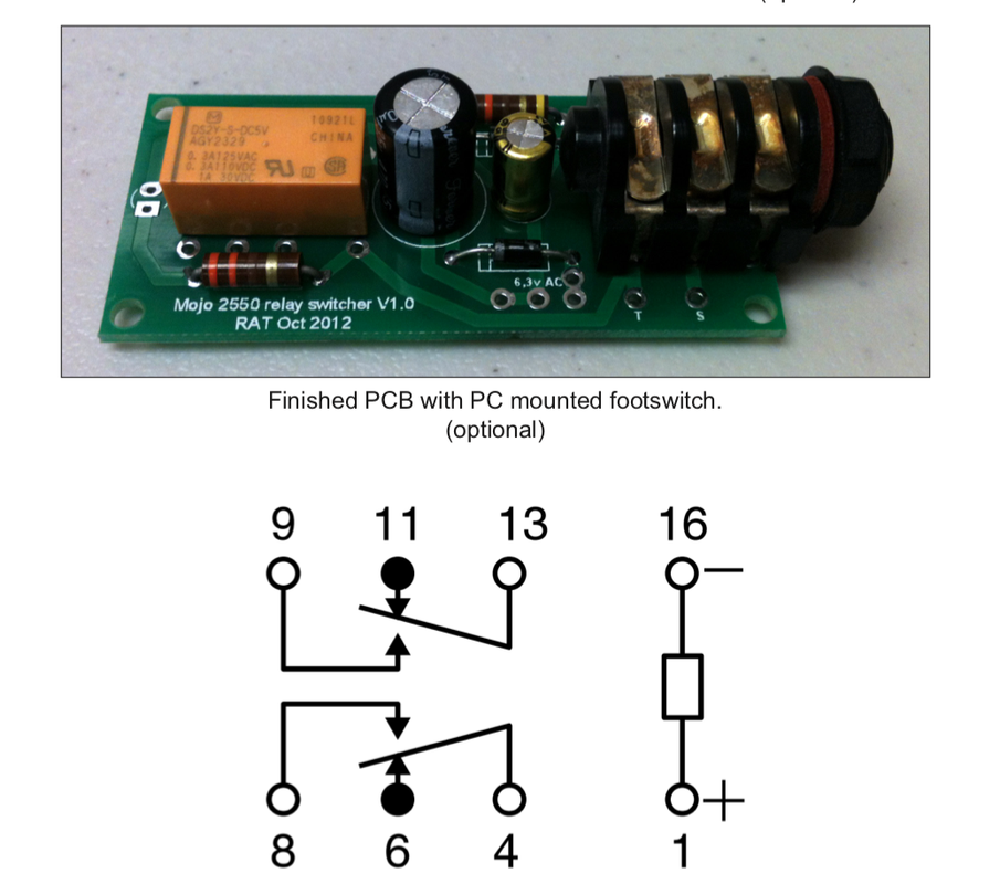 |
|
|
|
Post by angelodp on Nov 22, 2020 12:46:02 GMT -5
The Teeco amp so far 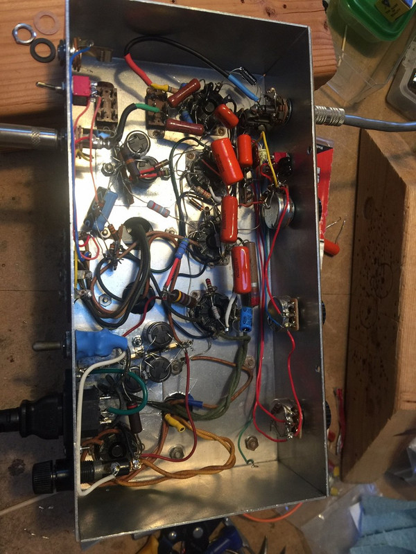 |
|
|
|
Post by sumgai on Nov 22, 2020 13:26:41 GMT -5
ange,
Do recall the Rule of Nutz: At all times, reTrEaD is always correct, and my posturing mumblings are to be ignored, or at best, to be considered an entertaining clown who sometimes (often) falls on his face.
Part 2 of that Rule: In many cases, ashcatlt also trumps anything I say.
That is all.
|
|
|
|
Post by angelodp on Nov 22, 2020 15:52:09 GMT -5
As always a gentile and helpful community. I shall work on implementation and report. My best to all, stay safe and well, I see light at the end of the tunnel.
Ange
|
|
|
|
Post by angelodp on Dec 6, 2020 12:19:45 GMT -5
An Interesting discovery. I have replaced the tonestack with a more traditional one. I am including the schematic. I have been trying a couple of variations in the slope resistor - 100k and 56k. When I first implemented this change I inadvertently used a 1k in the slope position and thought that was 100k. It turns out that when I used a measured 100k and or a 56k the stack does not work..... as in cutting out and sputtering. The 1k slope does work?? I have read where some Marshall tinkers have gone to 680R or 1K with some success. My question is - what is it about this circuit that is rejecting anything but a 1k-2k slope resistor? Best A 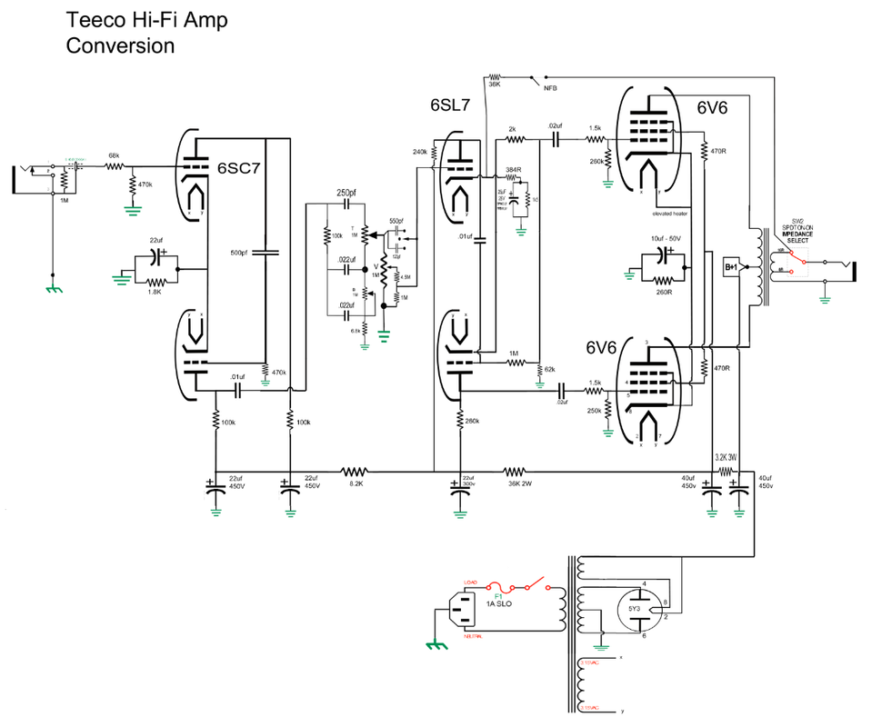 |
|
|
|
Post by angelodp on Dec 6, 2020 12:43:14 GMT -5
Gut shot 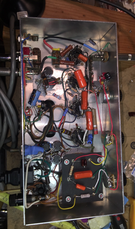 |
|
|
|
Post by reTrEaD on Dec 6, 2020 13:01:24 GMT -5
An Interesting discovery. I have replaced the tonestack with a more traditional one. I am including the schematic. I have been trying a couple of variations in the slope resistor - 100k and 56k. When I first implemented this change I inadvertently used a 1k in the slope position and thought that was 100k. It turns out that when I used a measured 100k and or a 56k the stack does not work..... as in cutting out and sputtering. The 1k slope does work?? I have read where some Marshall tinkers have gone to 680R or 1K with some success. My question is - what is it about this circuit that is rejecting anything but a 1k-2k slope resistor? The tonestack section in your latest schematic is tiny and it's almost impossible to see the component values. Also, I think your 'slope resistor' isn't connected correctly but I can't be certain because of the lack of detail when I enlarge the image. Could you post an image of just the tonestack? Won't matter if the volume control and brightness switch is included or not. I just need something where the image is larger. |
|
|
|
Post by thetragichero on Dec 6, 2020 14:55:33 GMT -5
could the stage after the tone stack be wanting a grid stopper? it's usually that or a missing grid to ground resistor that causes sputtering/misbiased fuzz sounds in my builds. maybe with the 1k slope resistor the tone stack is so lossy that grid current isn't an issue?
it should be noted i don't have much experience with preamp pentodes so i could be way off
|
|
|
|
Post by angelodp on Dec 6, 2020 15:24:49 GMT -5
Here is the tone-stack. I replaced the 100k with a 1k to get it working.  |
|
|
|
Post by thetragichero on Dec 6, 2020 16:58:09 GMT -5
humor me and throw ~33k (39k 47k. whatever's handy) from the volume pot middle lug to the next stage grid? i get these sort of issues when i try to implement old fender schematics since Leo was so frugal
|
|
|
|
Post by angelodp on Dec 6, 2020 17:24:10 GMT -5
Ok tried that, a 27k at the grid. Did no harm but was not able to up the slope resistor to any degree.
Cheers A
|
|
|
|
Post by thetragichero on Dec 6, 2020 17:40:33 GMT -5
okay fair enough
sure everything is wired correctly? this is the kind of maddening thing that results in me setting a build aside for fresher eyes and mind
|
|


 Also, is this a switching jack of any kind, or is it a bog-standard TRS jobbie? A switching jack might also contribute to your problem.


 I'll get back on it later tonight, but for sure, grounding that 36KΩ resistor will have a deleterious effect on your sound... not to mention on your tubes as well. In effect, it would short the bias supply to the cathode of the upper half of the tube, and pretty much cut off the signal, or at least send it into a non-linear region of operation. That latter part is the provender of what we call "distortion". Ugly. And potentially harmful to the tube's life, over the long run.
 )
)

