|
|
Post by newey on Feb 8, 2022 5:45:50 GMT -5
Well, he's explained (I think) why I like Esquires more than Teles. Interesting testing, but what I came away with is that every variable matters, but doesn't seem to matter much- until he got to fingering position, etc. So maybe, like tone, sustain is in the fingers?  |
|
|
|
Post by newey on Feb 5, 2022 14:02:52 GMT -5
Your HB has two coils, one coil will be RWRP ("reverse wound, reverse polarity") with respect to the other coil. Noise/hum is generated via the coil windings (they act as an antenna). The magnets and coil windings are both responsible for our guitar signal, but the magnets don't really play a role in the hum. So, by having one coil both reverse wound and reverse polarity of the other, the two coils remain in phase with each other- if we had changed either the winding direction or the magnetic polarity, but not both, the coils would be out of phase, cancelling a portion of the signal. But by swapping both, we maintain phase. But, as the two coils are reverse wound of each other, the noise induced into one coil is out of phase 180° with the noise induced into the opposite coil- and the matching frequencies cancel each other out.
This is essentially the same way that those noise-cancelling headphones work. A certain amount of ambient noise- in phase- comes into the headphones as they don't perfectly seal to one's head. To cancel this noise, a small microphone picks up the same noise from outside the 'phones, and the signal is then inverted so it is out of phase with the ambient noise- and the common frequencies cancel out.
So, there's a quick primer on Hum-cancellation. The bottom line is that, as between your neck and bridge pickups, you'll want to split the HB to the coil, either N os S, which is the opposite of the bridge SC pickup (because the Pickups are from the same manufacturer, it's a pretty safe assumption that "North" and "South" have the same meaning for both their HBs and single coils.) So, if the bridge SC is "North", you would want to split the Neck HB to the South coil, so that all positions where you have the neck split to a single coil will be hum-cancelling with the bridge. If the bridge is a "South", then the opposite coil of the HB is the one you want. This effectively makes your neck HB, when split, and your bridge pickup into a "widely-spaced" humbucker.
Now, you have 3 options. First, you may be able to find out on the web what the polarity of a Fender Mexican Tele bridge pickups is. If so, you should be good to go, just split to the opposite coil of the HB.
Second, if the pickups are not mounted into the guitar, you can check the polarity by placing the bridge single coil against each coil of the HB in turn, face-to-face. You want opposite coils, and as the saying goes, "opposites attact"
And, if the pickups are already mounted, a simple test with a child's toy compass will show which coil of the HB is opposite of the bridge.
|
|
|
|
Post by newey on Feb 5, 2022 12:07:01 GMT -5
hanonymously- Am I correct in assuming that the black wire from the phase switch is grounded to the back of the Vol pot? Looks to me like position 3 (neck coil split in series with the bridge) is wrong. You are spltting the neck HB to the North coil (green wire connects to output, white wire is grounded). But the bridge + is connected to the Neck HB red wire, which is the South coil. The other end of the South coil, the black wire, is disconnected at position 3. So, as shown, you will only have the neck N coil alone, the bridge pickup is disconnected. We have also not discussed hum-cancelling when you have the neck HB split in conjunction with the bridge SC. It's a Fender HB but you didn't mention the type of bridge pickup. You will probably want to check coil polarities to ensure that the split coil positions will be hum-cancelling with the bidge pickup.
|
|
|
|
Post by newey on Feb 5, 2022 9:14:54 GMT -5
hanonymously-
Hello and Welcome to G-Nutz2!jhng and angellahash are both correct- everything looks OK except position #2, your HB is completely disconnected at that position. And I, too, am making assumptions that the volume and tone pots are correct as the diagram is unclear. And, I'm with jhng on the resistors, not clear what you want to achieve there. Sometimes we want to attenuate the signal a bit in one or two switch positions, but you've got your bridge pickup permananetly wired to the resistor in all switch positions. So, you won't ever hear the single-coil "chime", even in position 1.
|
|
|
|
Post by newey on Feb 3, 2022 22:33:20 GMT -5
I'm not exactly following your diagram, although I'm assuming there's more connected to the paperclip than just one green wire. But as i said, if it works and isn't noisy, leave it be. "Don't mess with success" But in order for a star-grounding scheme to be properly done, the jack sleeve would be connected directly to the star ground point/paperclip. And . . . we have now thoroughly hijacked thedirestrat's thread. Sorry! |
|
|
|
Post by newey on Feb 3, 2022 18:18:39 GMT -5
Not clear what you mean here. The jack sleeve is the end point. Since a picture may help, here's a stylized diagram of a star ground scheme, using a washer and screw into the copper shielding as the star ground point. Signal grounds (the pickup "not hot" wires and the ground connections from the Vol/tone pot lug(s)) do not run with or through the shield grounds (the braided shield wires from the pickups, the bridge/string ground, the copper shielding) until they reach this point, and then are connected to the output jack sleeve. 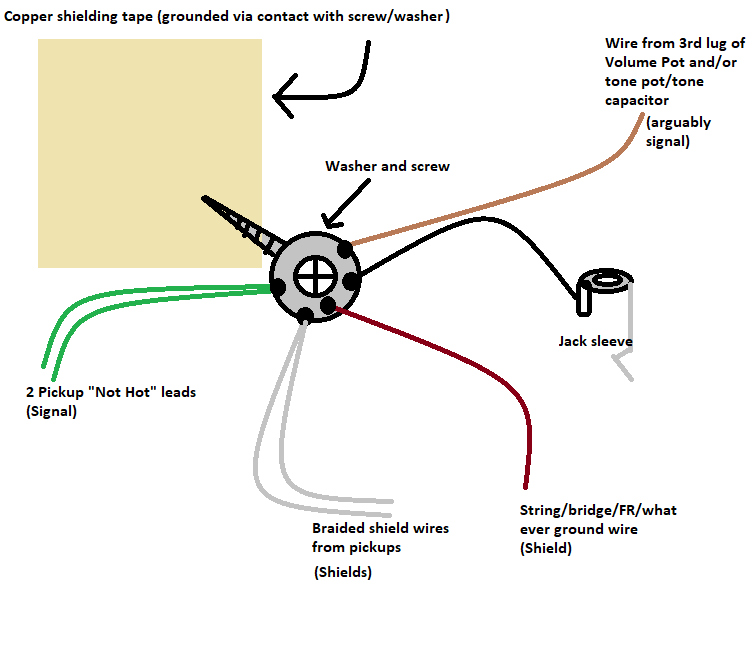 (Note that I labelled the wires from the vol and tone pots as "arguably signal"- they really aren't carrying signal, they're just grounding the third lug of the volume pot and the tone cap, but I'm treating them as if they were carrying signal) In my example here, the shells of the pots are assumed to be grounded via contact with the copper cavity/pickguard shielding, so there are no separate wires run for the shells. If there were, these would also be shielde grounds, not signal. Same as for grounding the frames of any switches or other components. |
|
|
|
Post by newey on Feb 3, 2022 16:00:13 GMT -5
so how does sending signal/shield ground through shield ground on its way to my star ground create noise or other maladies? Well, we don't know for sure about noise, but in theory it could make a difference, so best practices is to avoid it. It wouldn't "create noise", the noise comes from the outside world, the question is whether it gets introduced into your signal or not. Let's be clear. If you simply wire one pot casee to another (i.e., daisy chain them together), and there is nothing else connected to the pot cases, that is just shielding- which would then be connected to your star ground in some fashion, hopefully. Now, if you have shielded the underside of the pickguard (or the cavity, if it's a rear-routed axe), then your pot cases should also be grounded through the shileding, which should also be connected to your star ground point in some fashion (usually via contact/screw) So the daisy-chained wires are a duplicate path, not really needed, but as you said, the pot may come loose at some point, so perhaps more secure to wire it as well. But if you grounded the pickup "not hot" wire to the back of the pot as well, that's a signal connection- and your pickup's signal is now traveling through your shield ground. This is not "wrong", guitar manufacturers do this all the time, but it sort of defeats the purpose of your star grounding. If you're star-grounding, you'd want that pickup "negative" connection to go to the star ground directly. Again, this is a "best practice", not an absolute. Star grounding your guitar may make zero difference in the noise level. But in theory it could make a difference, so we do so to avoid a potential risk of introducing noise into our guitar signal. While guitar manufacturers typically daisy-chain ground wires from pot to pot, and then to the jack -, if you open up virtually any piece of active electronics equipment, like a radio reciever or stereo, you'll find the signal path has been star-grounded. Those manufacturers do so because it may reduce noise, it's a best practice to do so. But it does take more effort to do so, so guitar manufacturers stick with the philosophy of "we've always done it that way" . . ."if it was good enough for ol' Leo Fender . . ", etc. |
|
|
|
Post by newey on Feb 3, 2022 15:34:00 GMT -5
I'd guess that if resistors were introduced on one side or the other, that would change the mix, but I might be totally wrong. Or it might not be useful anyway. What say ye? I'd say it's been done, numerous different ways and different times. If you want a mix of volumes, for one pickup versus the other, a series of appropriately-sized resistors would do the trick. This could be done on 2 separate rotaries, one for each pickup, or on one single rotary with a pole for one pickup, another pole for the other. ashcatlt is the one to ask. He hates pots  . He has a Ric with nothing but rotaries to control both volume and tone. |
|
|
|
Post by newey on Feb 3, 2022 12:02:34 GMT -5
Did I not ground correctly? Well, I'm not sure what you mean by "incorrectly". You said you wired from the pot shells to the star grounding point, as opposed to relying on the contact through the shielding. That is fine, although I wouldn't worry about grounding the pot shells only to the shielding. If you did not wire the jack sleeve to the star grounding point, though, I'd be concerned about that. If it works, fine, I'm not saying you need to open it up and change it. But if it stops working, that would be the first place I'd look. As we have said repeatedly, we don't want to use shielding to carry signal, just as a "best practices" kind of thing. Your star ground point collects all the grounds, both signal grounds and shield grounds. We should not be relying on mere contact with the shielding to connect the star ground point to the output jack sleeve, as the wire from the star point to the jack sleeve is part of the signal path (as well as of the shield path). Hope that clarifies what I meant. |
|
|
|
Post by newey on Feb 3, 2022 5:56:18 GMT -5
But just to get one thing straight: Star grounding is when you solder all your grounds to one place, correct? Like the back of the volume pot, or a washer attached to the shielded cavity? All signal grounds and shield grounds will be separate until they reach the star grounding point, where that is attached to the jack sleeve indirectly (either through volume pot casing, or cavity that connects to the volume pot via well "metal on metal"?) Yes, all signal grounds and shield grounds should be separate until they meet at the star grounding point. But the star ground point needs a wire to connect it to the jack sleeve, you don't want to rely on shielding to carry that connection. Whether you wire from the pots to the star ground point, as unreg has done, is up to you, but there is no "indirectly" connecting to the jack sleeve. If you are going to ground things to the pot casings, then it's probably best to "daisy-chain" them rather than trying to use one pot back as a star grounding point- you'll end up with too many wires to be soldered to the back of the one pot. |
|
|
|
Post by newey on Feb 2, 2022 6:53:13 GMT -5
One of the advantages to using a star grounding scheme, as unreg says, is to avoid soldering to the pots altogether. The back of a pot could certainly be the point where you put the star ground, but that's a lot of wires to solder to the back of a pot. Typically, when grounding to the backs of pots, the grounds are not star-grounded, they're daisy-chained from one pot to another. Nothing wrong with that, guitar manufacturers have been doing it that way for 70 years or so. There are any number of ways to wire a star ground. A washer, screwed into the side of the cavity and with ground wires soldered to it is probably the most common way. You need to clean the washer with a solvent and also sand it a bit to get good solder adhesion, but you can avoid soldering to pots that way. The pot cases get grounded via contact with the shielding of the cavity and/or pickguard.  Becasue a solder connection is more secure than a screw connection. We're talking the bridge end of the wire, not the end that goes to ground in the control cavity (which goes to the ground point, wherever that is, back of a pot if that's what you're doing). Typically, there is a channel for the wire to go from the bridge to the control cavity, the end of the channel keeps the wire below the surface mostly. Might have to enlarge the "divot" at the ends of the channel a bit, but once you screw the bridge plate down ir should be flush, it's not like you need a big blob of solder to hold the wire. Set your meter to read resistance (Ω) Test between the pot case and the shielding. You should see at most a few Ohms. Low resistance equals a good connection. Check between the bridge plate and the jack sleeve lug. Again, should only be a few Ohms. However, if the bridge plate is chrome-plated you may get a poor reading, so try to test to the saddle screws or something else that's not plated. Ideally, you'd test to the strings, but we're assuming the guitar is unstrung at this point in the operation. As I said above, they can only be kept separate for so long, they all have to ultimately meet at the jack sleeve. If you collect them all on the back of a pot, and then the pot back is wired to the jack sleeve, that's as far as you can go in keeping them separate. What we mean here is that you should not be running the guitar signal "ground" (or "not hot") through any portion of your shielding or shield ground wires, to avoid potentially introducing noise into the signal path. Two separate blobs of solder is meaningless in terms of grounding- they're both going to the same place. Probably be easier to solder them that way, as opposed to one big blob, but I try to avoid soldering to pots at all, as unreg said. I've fried a few pots that way over the years. Modern pots are mostly plastic inside, it's fairly easy to to melt the innards. |
|
|
|
Post by newey on Feb 2, 2022 6:11:02 GMT -5
You certainly can have the switching the way you want it (at least, I think you can, we haven't put pen to paper yet, but I can't see why it shouldn't be possible as you describe it). With guitars equipped with regular HBs with similar coils, I'm a big fan of the parallel HB as opposed to splitting the coils. But the P-rails are a different animal, the whole point is being able to have the individual coils. But I'd want the parallel HB option as well.
The global series/parallel? Many players aren't fond of putting 2 HBs in series as it can sound a bit "muddy". But again, these aren't regular HBs so who knows?
|
|
|
|
Post by newey on Feb 1, 2022 21:29:55 GMT -5
jackfawkes-
Hello and Welcome to G-Nutz2!I won't claim to have all the answers but I have some . . . And I'm switching the order around a bit to take the easier ones first.  The pickup cavities are the most critical to shield, but my philosophy is, if you're going to have the whole shebang torn apart anyway, might as well shield everything. The control cavities are unlikely to be a source of significant noise, but I'm not going to tell you it can't happen. So, do it all and do it right just to err on the side of caution. People who have used the shielding paint have claimed good results with it, but it takes a few coats. I'm a big fan of the copper shielding tape with the conductive adhesive. It's pricier than some other options but does a good job and so long as you overlap the pieces, you don't have to worry about continuity across your shielding, it's all connected via the adhesive. We've had several people post wiring schemes for the P-rails, but I don't recall any actually being built, nor can I recall anyone reviewing the pickups. The theory of the thing sounds intriguing- two entirely dissimilar coils mated into a humbucker. I'm not personally a big fan of rail-type pickups; if they made a "P-Strat" humbucker, I'd be more interested. Certainly, though, the dissimilar coils makes for a lot of possibilities with splitting the coils, series/parallel as you have done. ! It sounds rational, but perhaps a bit inefficient. You don't like the look of the Triple Shot™ rings, but the way they are wired is less involved than what you have, and gives the same options. The two switches on the rings are wired in what we call a "binary tree" arrangement- Both switches in one direction gives series HB, both switches in the other direction gives parallel HB, one switch to right, one to left gives the P90, opposite gives the rail coil alone. So, you get all 4 options with 2 DPDT On-On switches, instead of a 3-way and a 2-way. The triple shot scheme could easily be adapted to 2 toggle switches or slide switches, wherever you decide to put them. Of course, if you're looking to reuse the existing switches, that will limit the options. As for location, if it were my guitar, I'd put the switches to control one pickup (however wired) on the lower bout, and the other pickup controls on the upper bout. The 3-way pickup slector could go either place, along with a global series/parallel switch as you suggest. The first option. With separate TBX pots for each pickup feeding into a master volume, you'll have interaction between the two TBX pots. Some of that could be alleviated by using a dual-gang volume pot, but you'll still have some interaction when both pickups are on. And, if you want to have that global series/parallel switch you mentioned, the dual TBX pots are going to present challenges with the pickups in series. A matter of personal preference, but you said you'd mostly be using the P-90 coils. If so, I'd want the P-90s to the outsides, so that the bridge pickup gave me the more treble tone for leads, and the opposite on the neck, more jazzy-bassy sounding- IOW, max variation between the 2 coils I'd be using the most. Pot values and cap values are also personal preferences, but 500K for the pots is certainly reasonable (and standard) given that, after all is said and done, these are two humbuckers. |
|
|
|
Post by newey on Feb 1, 2022 20:48:05 GMT -5
The only source for true-blend pots we were ever able to definitively identify was OEM Fender. I don't know whether they are linear or audio, but I suspect audio. And I have never seen a 500K/1M dual-ganged pot. 500K/250K are available, but I think those are audio taper and not true blend pots either.
|
|
|
|
Post by newey on Feb 1, 2022 20:44:20 GMT -5
but that is using the STARTS of each coil rather than the FINISH..? Does that have to do with the RWRP wiring? I think I have much to learn still.... The "dual rail" pickup is not "RWRP", it is a humbucker. It has two coils; one is reverse-wound, reverse-polarity with respect to the other coil, that's how it cancels the hum. You're over-thinking this. Forget "Start" and "Finish", you don't need to worry about that. Just wire it as suggested by Dragonfire. As we mentioned earlier, since you are using 2 different brands of pickups, testing for phase before installation is recommended. if it is out of phase with the other pickups, you'll simply need to go back in and swap the green and black wires. But better to test it beforehand to avoid having to go back inside to fix it. Ounce of prevention and all that . . . |
|
|
|
Post by newey on Feb 1, 2022 9:16:45 GMT -5
I would cut it where it comes out of the POT personally I agree. Also, you have reversed the "up" and "down" labels for the middle pickup. As shown, "up" will be "on", which is, I think, the way you would want that to work, but your text says the opposite. Other than that, the diagram looks fine. |
|
|
|
Post by newey on Feb 1, 2022 8:55:32 GMT -5
Does shielding, like copper shielding a pickguard and a control+pickup cavity, need to be grounded? On my Strat, I soldered a wire on a wall of the cavity and connected it to the volume pot (to ground). This is not an unnecessary ground connection because the shielding should technically be touching the volume pot and maybe ground because of that? Yes, shielding needs to be grounded. It is also helpful, I think, to distinguish between signal grounds and shield grounds. Both sets of grounds ultimately need to connect to the output jack sleeve/barrel, but ideally we want them separate until some point shortly before the jack. There's no harm in running an extra wire, but you are correct that the shield should be grounded to the pot casing (which is then grounded in turn). But if you are going to rely on contact between the pot case and the shielding, best to check that connection with your meter to be sure it makes a good ground. (Should read at most a few Ohms). Correct. But check it with a meter just to be sure. I have also scraped the underside of a Tele bridge plate with a scratch awl (so as to roughen up the surface for a good solder connection) and soldered a wire to the underside, which is then run to the cavity. Your "grounding diagram" looks fine, however, with the phase switch on the neck pickup, the pickup cover must have a separate shield wire, it can't be the signal ground as well (which is how most Tele pickups are wired). If I recall from earlier in the thread, I believe yours are custom ones with a separate wire for the cover shield ground, which is fine. But with "stock" Tele neck pickups, the cover ground has to be disconnected from the coil ground and a separate wire run, in order to add a phase switch to the neck pickup. The same is true if the phase switch is on the Tele bridge pup- the baseplate needs a separate shield ground wire. The point of the ChrisK reference is that "ground" is a DC term, and we're talking AC, so it's a bit misleading. But we use the term "grounding" in our discussions of guitar circuits as a convenience. This has nothing to do with metal surfaces. Things like metal covers should be "grounded" to reduce noise. These are shield grounds, they are not carrying our guitar signal. But we also need to "ground" (or, alternatively, you could say "attach the 'not hot' wires") to the output jack sleeve/barrel in order to form a complete circuit. The barrel sleeve is then ultimately "grounded" via one conductor of our guitar cable, and then into our amplifier, where the circuit is completed. The amp is then ultimately grounded through our household circuitry to the Earth (which is why our UK cousins refer to the ground connection as "earth"). |
|
|
|
Post by newey on Jan 31, 2022 12:59:27 GMT -5
I’m not saying that treble-bleed is pointless; it just wasn’t possible for me at the time… and I love how my treble-bleed-less guitar’s tone turned out! 😀 A treble bleed on the volume pot wouldn't have (and won't) affect your tone pot, and won't affect the guitar's tone with the volume at "10". The treble bleed only has an effect as you turn the volume control down. You could have, if you wished to do so, put one on the volume pot along with the 1Meg resistors on the tone pot. |
|
|
|
Post by newey on Jan 31, 2022 6:38:54 GMT -5
I still have to figure out the push pull pots (the blend one especially) OK, here's another quick lesson. 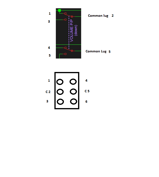 Yogi has helpfully employed dotted lines to indicate the 2 poles of the push/pull switch. Sometimes, rather than dotted lines, the switch poles will be lettered/numbered as we did with the lever switch. Again, the numbering is arbitrary, but like the lever switch, each pole is independent of the other. In one position, the Common lug "2" connects to 1; pulled up, it connects to 3, and 5 connects to either 4 or 6 on the other pole. Just like the poles of the switches, the pot element of a push/pull pot is independent of the switch, unless you connect them together for a particular wiring scheme. So, on Yogi's schematic, the pot portions of the push/pull pots are shown entirely separate from the switch part; they are in reality two separate components controlled by a single shaft. Your phase switch is similar to the above, but it is a 4-pole double throw toggle switch (4PDT), so it has 4 common lugs, as shown. |
|
|
|
Post by newey on Jan 31, 2022 6:10:57 GMT -5
sumgai- Something isn't computing for me. I'd like to buy a clue please, Pat. His Volume pot is 500K, tone pot to be replaced with a 250K in lieu of the 500K one with resistors. But you're right, a treble bleed is useful either way. What's confusing is that unreg seems to be saying a treble bleed on his new tone pot; it's the volume pot that should get the treble bleed.
|
|
|
|
Post by newey on Jan 31, 2022 6:03:49 GMT -5
Sad. I hadn't heard that, and didn't realize he was the last. I'll have to run through "Pipeline" at my lesson tonight in honor.
This one is more a feature for Mel Taylor, the drummer, but I just love this version of "Wipe Out", live in Japan in 1966:
|
|
|
|
Post by newey on Jan 30, 2022 21:59:38 GMT -5
those A1 and C1 aren't connected right? The only thing that "connects" is the common terminal and the terminal in one of those 'circles' (poles), such as CA and A1. Is this correct? Yes. After I posted that, I realized using different colors to show the connections on different poles, rather than making them all red, would have been clearer. But, yes, each pole is independent of the others (unless you connect them together). No need to do so. The tone pot connects there, and the switch pole, but the third wire can just be a jumper between the uppermost switch pole and the lowermost pole. So, two wires connected to the common lug of the upper switch pole, and two to the Vol. pot. Yes, assuming you are using the back of the volume pot as the grounding point. Correct, the green squares where two wires meet indicate a connection. No green square, no connection. Maybe. They don't connect, which is what you mean. But "in real life" they might not cross, they might not even be anywhere near each other. Keep in mind that a schematic diagram has nothing whatsoever to do with the physical locations of things. |
|
|
|
Post by newey on Jan 30, 2022 7:59:32 GMT -5
Again, how do you know which one of the lugs correspond to A1, B1, etc? The lettering of the poles, just like which end is "1" versus "3", is arbitrary. You can designate any one of the poles shown on Yogi's diagram to be "A", "B", etc- you just have to wire each one consistently with the diagram. Lettering the poles and numbering the other lugs is just a convenience, it's easier to talk about a particular diagram here if we can refer to "CA" rather than "the pole where the green wire attaches" or some such description. |
|
|
|
Post by newey on Jan 30, 2022 7:43:42 GMT -5
@angellahash: And how I read this (so maybe wrong) Potentiometer setup with 1M between lug 1&2 and 2&3 No, he's got 2 1MΩ resistors, both wired in parallel between lugs 1 and 3 of a 500K pot, to give an effective resistance of 250K. |
|
|
|
Post by newey on Jan 29, 2022 22:45:17 GMT -5
Simple question: If I remove my 500K audio taper tone pot, with its 2 one meg resistors, across lugs 1 and 3, that reduce it to 250K, and replace it with a resistor-less 250K audio taper pot; will my tone change? It won't change it much at "10", but those resistors alter the effective taper of the pot, so as you turn the tone control down, it won't operate quite the same. Whether the difference is for the better or for the worse is for you to decide. |
|
|
|
Post by newey on Jan 29, 2022 22:39:02 GMT -5
Does "2" mean center? Does "3" mean lever up? "2" is the center, yes, which end is "1" or "3" is arbitrary. I drew the diagrams following the Fender convention (which more or less holds) of designating the bridge position as "1", meck as "3". Yogi's schematic does likewise. So, lever "down" is towards the bridge pickup, connects the "1" lug to the common lug, "3" is with the lever up. Note that the position of the lever is opposite of the lugs which are connected- that's why they call it a "lever switch" . |
|
|
|
Post by newey on Jan 29, 2022 8:50:31 GMT -5
It's not just for the blender that you need a 4 pole switch, you also need the extra poles for switching between your coil taps. I think your picture of the regular 3-way switch wiring would be easier to follow if you re-labeled A4 and B1 as the common lugs -"CA" and "CB", perhaps, and then also renumber 1,2 and 3. So, before we move on to discuss your 4P3T switch, let's designate the regular 2P3T switch in a more understanable fashion: 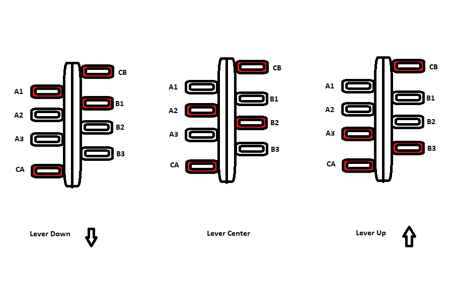 Now, the 4-pole switch may vary, so once you have the piece "in hand", you will want to check it with a meter to be sure that it operates in the way that I have shown here. But the majority of such switches should look like this and operate in this fashion: 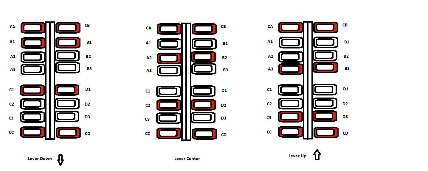 Now, the tough part is translating Yogi B's schematic drawing into a wiring diagram that you will use to do the actual soldering. In a schematic, the 4 poles of the switch may be (and are) disambiguated; they are positioned where they need to be electrically, not in actuality. So each pole of the 4-pole switch as shown on the schematic looks like this: 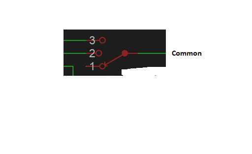 This should allow you to translate the one into the other. |
|
|
|
Post by newey on Jan 27, 2022 16:04:08 GMT -5
Tongue is the best battery tester  Don't try it with your Tesla . . . |
|
|
|
Post by newey on Jan 26, 2022 16:54:49 GMT -5
OR MAYBE THERE'S NO DEDICATED PICKUP "HOT" AND "GROUND" LEADS! Your pickup generates an AC signal. "Hot" and "ground" are more accurately used to describe DC circuits. In reality, the hot and ground from your pickups are alternating at the frequency of the vibrating string(s). We use the terms "hot" and "ground" just becasue we have to have a way to designate one end of the AC circuit from the other. (ChrisK used to call them "hot" and "not hot" to emphasis that there is no absolute ground, as there is in a DC circuit). Wire colors won't help you sort out the phasing unless the pickups are identical. That's why we usually recommend testing for proper phasing if there is any uncertainty. Yep. No-Load pots are more usually used as tone controls. The transition from the no-load portion of the track to the resistive portion can be annoying when used as a volume pot. There's no reason you can't try it, but if the goal is to minimize the number of times you have to go back inside the thing, the few dollars a new pot would cost would be worth the extra time and trouble if you decide you dislike the no-load as a volume. |
|
|
|
Post by newey on Jan 25, 2022 19:29:56 GMT -5
ztan-
Hello and Welcome to G-Nutz2!
Thanks for some definitive answers to this old question. I think you've confirmed at least that it is not terribly different from similar products. I haven't searched, but I'm not sure these things are even still available.
And, piezos have come even further in the decade since I posted that. I was listening to a guy play a nice piezo-equipped acoustic/electric at the local music store a few months ago. He was playing it through one of those 7-band equalizer pedals and was able to "dial in" a convincing acoustic sound.
|
|


 . He has a Ric with nothing but rotaries to control both volume and tone.


