|
|
Post by newey on Jan 17, 2024 11:53:58 GMT -5
ssirch- Hello and Welcome to G-Nutz2!First off, your pot and cap were not "underrated for a humbucker", a 500K pot is just a suggested value, and some folks prefer other values. Same with capacitors, it's a matter of individual preference. 1.0µf; is pretty big, typically people use 0.022µf; or 0.047µf; But the size of the cap only comes into play as you turn the tone knob down, the differences in value "move the knee" (as we say) in the frequency response curve. IOW, the tone changes at a different point along the rotation and at a different rate of change. But with the tone at "10", the guitar will sound basically the same regardless of the cap value. As for the grounding, the tone pots, etc will be grounded through the plate, assuming the plate is, in turn, connected to the output jack sleeve. If you have already grounded things to the back of the pots there is no need to change anything just because you are using the steel plate. No, so long as both are grounded somewhere.
|
|
|
|
Post by newey on Jan 17, 2024 5:51:27 GMT -5
Is the hum reduced when you touch the strings?
Grounding the pots is probably more important than grounding the switches, but they should be grounded to the grounding point, where all of the grounds are before they are wired to the output jack sleeve lug.
Many hollow-bodied guitars don't ground the bridge/tailpiece, and I don't know if the Gretsch Rally does or not. If the guitar originally had a bridge/tailpiece ground, there would be a small hole for the wire, either beneath where the bridge sits or under the tailpiece- more likely under the tailpiece. If there is such a hole, then by all means try replacing that ground wire- the other end gets grounded to the grounding point, and then to the jack - . If there's no hole there, then there never was a factory bridge ground and I wouldn't worry about it. If there never was a hum problem before (and "static" sounds like a different issue anyway), you probably need to look elsewhere for the source of the noise problem.
Having said all that, hollow-bodied guitars without a bridge ground do tend to be a bit noisier than if they had it, but the noise level is usually not a big issue until someone wants to play one through high gain pedals or amp settings. If the noise floor is tolerable at clean settings at reasonable volume levels, and only becomes an annoyance when playing with high gain, then it may be one of those "nature of the beast" things. A noise gate pedal may help in that case.
|
|
|
|
Post by newey on Jan 16, 2024 21:19:00 GMT -5
Please report back if you get it wired up and playable. Glad we could help, if it works out.
Some of those import 5-ways will have a tiny bare wire jumper between the poles, other connect the 2 poles internally. At first, this didn't seem to make much sense to me. After all, there are import 5-way switches with only 7 lugs, with a single common lug in the center.
But what I suspect (without any proof, but seems sensible to me) is that the internal connection is deemed more durable than the jumper, and the same switch body with the 8 lugs is used for multiple switch configurations, they just swap out the inner contact plate. Or so I figure it, anyway.
|
|
|
|
Post by newey on Jan 16, 2024 13:12:45 GMT -5
@dynamiteblossomseed-
Hello and Welcome to G-Nutz2!
Some of these import-style 5-way switches have the two common lugs connected internally, so I suspect that's what's allowing your tone controls to function at all. If you have a multimeter, you can check to see if this is the case. But if, in fact, 6-7-8 are all connected to together, then you are correct, it makes no sense that you would have separate tone controls. First, perhaps despite the "blob", one of the 3 is not in fact connected to the other 2- that would explain it. Again, a meter would tell the tale.
Did you actually check to see that, if you select the neck pickup by itself, the bridge tone does not also affect that pickup? Is that bridge control truly independent?
Assuming that you checked that, I can't explain what you're reporting. Maybe someone else has some insight.
|
|
|
|
Post by newey on Jan 13, 2024 22:10:06 GMT -5
xhrist- Not clear on what exactly the Freeway switch is going to be doing here, since you mentioned other switches for the coil splits and another toggle for the two middle pickups. It's probably best if you draw up what we call a "truth table"- i.e., a chart showing all the different switch combos you want. I built a 4-pickup Strat with a pair of Fender Vintage '57s and a pair of Vintage '62s. One pair was in the first and third positions, the second pair at 2 and 4. So, with your layout, you'd be combining like with like- the two single-coil sized HBs are switched together and the 2 PAF-style ones are the other pair. Then the two pairs get combined. Just a thought.
|
|
|
|
Post by newey on Jan 10, 2024 12:42:08 GMT -5
Yeah, that probably needs clarification since I didn't mention the center switch position on the pickup slelectors. For either pair of HBs, with the series/parallel switch "down" (series setting), the 3-way pickup selector will give you the following: 1) Selector switch "up"= Lower HB in series with upper HB 2) Selector switch in center = Lower HB in series with upper HB, with the series pair in parallel with the lower HB3) Selector switcch "down" = Upper HB only I don't know what that center combo would sound like since the pickups are dissimilar. It probably would not be mucjh different from both HBs in series, but I could be wrong on that. Here's the skinny on how to do this via overriding the 3-way switches. A lot of the discussion therein has to do with the "Jimmy Page mod" which doesn't apply to your build, but the basics are the same. guitarnuts2.proboards.com/thread/8215/global-series-switch-guitarnutz-properEDIT: sumgai beat me to the link to this. But if you have trouble digesting schematics, there is a wiring diagram further down in that thread. |
|
|
|
Post by newey on Jan 10, 2024 6:15:09 GMT -5
xhrist-
Hello and Welcome to G-Nutz2!Where did you find that diagram? I'm curious because it'll work but it's wonky, and there's a better way. The issue applies to both pairs of HBs since both pairs are wired the same way. First off, let's define "switch up" as meaning when the upper lugs of each switch are connected to the center (common) lug as shown on the diagram, and "switch down" to be the opposite. Which direction the switches are oriented IRL may be different than the diagram, but we're just dealing with the diagram here. The issue is that, with the series/parallel switch "up", you will only have the series connection of both HBs when their respective selector switch is in the "up" position. If the selector switch is down, you'll have one HB by itself (the upper one of each pair as shown on the diagram). So, it will work but would require manipulating 2 switches, potentially, to get the series setting. This issue is fixable, you need to have the series/parallel switches override the selectors, so that flipping to the series setting gives you both HBs in series regardless of which way that selector switch is set. So, if you use the diagram "as is", it will work but the switching will have that issue. If that's not a deal-breaker for you, fine, you can use the diagram as is. If you'd prefer to have the series/p[arallel switch override the selector, we can help you to do so. We'd have to take a look at that, but it will definitely require more switching. I suspect a 4-pole switch would be required at a minimum. These are available, but they are sizeable and you will already have a cavity that's pretty full with 7 switches as it is, not sure you'll be able to cram more switching in there.
|
|
|
|
Post by newey on Jan 8, 2024 21:15:19 GMT -5
ssstonelover- When sumgai says "RF cable", he means a wireless system. It's an old sort-of jokey reference from the early days of the Board here, not sure offhand whether it was ChrisK or sumgai who coined it. But the joke being that the best cable was no cable at all. I've had a few guitars that used barrel jacks, I've never used one in a build myself (but then I'm also not doing any woodworking, either). Never had a problem with them in any guitar I had- but then, I'm playing, usually seated, in my house, not jumping around onstage, yanking on the cable (if not an RF type cable . . .). I can see where excess ham-fistedness might well play a role here. If there is a potential failure mode for any piece of gear, I'm probably not pushing the envelope in my bedroon enough to trigger whatever failure mode there might be. Again, I'm just spitballin' here, ya unnerstand. But part of me wants to think that perhaps the closed confines of the barrel are less forgiving if the plug is not inserted straight in when first pushed in. Plugging in on a dark stage, often by feel if the jack is on the lower edge of the body, could result in repeated insertions at a bit of an angle, until the point where the plug's shaft fully engages into the jack. maybe the open frame is more forgiving of that sort of treatment. I dunno, just speculating.
|
|
|
|
Post by newey on Jan 7, 2024 8:33:34 GMT -5
Welcome Back, angelodp! Been a long time for sure. There are issues with your diagram, mainly that the bridge pickup's + connection is not connected to anything at position 3. As far as if it's out of phase, it could well be, switch the connections for the neck pickup and see. With two different pickups, there are no guarantees on the North/South coils being the same. sumgai did this schematic for a 4-way Tele switch:  His is sort of the mirror of yours in that your version has the bridge pickup permanently grounded for the end of the"series chain" while his permanently grounds the neck pickup. Also, yours has the series connection at the 4th position, his puts the parallel and series connections on the middle of the switch (which is, to me, a more logical switching order, since the single-pickup selections are at the ends, where we would expect them to be on a regular 3-way switch). My advice would be to rewire it using his diagram, but if you'd rather stick with what you started doing, holler back and we'll try to correct what you've got. |
|
|
|
Post by newey on Jan 7, 2024 8:08:37 GMT -5
tlg1100-
Hello and Welcome to G-Nutz2!What type of switching does it have? Is there a separate switch for the coil splitting? And, look for at least a third wire from the HBs. We can probably suss the wiring out from a despription of the pickup wire colors and switching. "Gobs of solder" sounds like someone went in there before to fix something (and failed). If the neck pickup is connected but not working, could be just a bad connection but also might be a busted pickup, maybe that's why they went in there to begin with. If you plan on repairing this, a multimeter to test the neck and middle pickups would be a good first step
|
|
|
|
Post by newey on Jan 1, 2024 10:20:24 GMT -5
owasis- Hello and Welcome to GNutz2!If it worked OK, then suddenly stopped, it's not a wiring issue, it's a bad connection. If you can access the cavity without removing the strings, hit the solder joints with your iron to remelt the joints, that may fix it. Gently tug each of the wires to be sure it's solidly connected. If you have to remove a pickguard to get at the wiring, I'd do the same, it'll just be a larger PITA.  If that doesn't work, some further investigation with your meter will be in order.
|
|
|
|
Post by newey on Dec 25, 2023 7:43:00 GMT -5
Merry Christmas to all the Nutz!
|
|
|
|
Post by newey on Dec 23, 2023 7:40:53 GMT -5
thed- Hello and Welcome to G-Nuts2! The diagram you have posted from Warmoth is for a 3-position switch- a DPDT On-On-On switch, also called a DPDT "center on" switch. In the center position, it gives both pickups in parallel- it's essentially using a DPDT On-On-On as if it were a regular Gibson-style three-way toggle switch. Which is what you said you didn't want. For myself, I'd like to have the option of both pickups together, even if it's not much used. But, you want what you want and we'll get you there. I suppose, depending on one's style of playing, being able to flick a 2-way switch between neck and bridge without the chance of it landing in the middle position might be useful. If you buy a DPDT On-On switch, a regular two-position DPDT, and wire it as per the diagram, you'll have what you want. But you could simplify the wiring considerable from what the diagram shows. Consider that every extra solder joint is a potential point of failure, so minimizing redundant connections is always a good idea. For what you want, you only need to use one-half of a DPDT on-on switch. In other words, this could be done with just a SPDT switch, if you haven't already purchased the switch.. If you have the DPDT already, center lug on one side (pick either side) is wired to output, just as the diagram shows both center lugs being wired. Neck + goes to the "lower" lug of that same side of the switch, bridge + goes to the "upper" lug. I put upper and lower in quotation marks since a toggle switch lever is in the opposite direction of the lugs connected. Of course, you can simply rotated the switch to get the toggle to point towards the neck pickup when in the neck position, and vice versa, presuming you leave enough slack in the wires to rotate the switch.
|
|
|
|
Post by newey on Dec 22, 2023 21:05:37 GMT -5
Whether anyone wires this or not, I am in favor of forevermore calling it "Dangle"  |
|
|
|
Post by newey on Dec 22, 2023 7:14:32 GMT -5
Correct, and that means you want the screw coil when the HB is split. The wiring I suggested does that, so no changes needed (unless the phase issue requires changes).
|
|
|
|
Post by newey on Dec 21, 2023 23:14:50 GMT -5
OK, before you wire things, check each coil of the HB against the middle pickup. Hold the two face-to-face. Which HB coil is attracted to the middle? Knowing this will allow for hum-cancellation in position 2, as we will split to the bridge coil that is opposite of the mid pickup. That still leaves the question of proper phasing. You could just wire it up, you have a 50-50 chance of getting it right the first time. Getting it wrong means going back in and reversing the connections on the HB, swapping hot for ground. So, to avoid the likely hair-pulling you'd suffer if the odds don't fall your way, it's best to test in advance. To do so, you will need to do the Screwdriver pull-off test. |
|
|
|
Post by newey on Dec 21, 2023 13:00:26 GMT -5
Also, if you want the V and T controls on the neck to be operable when the neck on switch is pulled, wire to the V pot instead of directly to the output jack. I was thinking "direct out" for some reason
|
|
|
|
Post by newey on Dec 21, 2023 6:15:07 GMT -5
There is a middle category. Mass-produced pedals from reputable brands. MXR, Boss, ElectoHarmonix, etc. You're unlikely to find garbage components in these brands but they are reasonably priced. Yet they are not at all 'boutique'. Not only that, but when you mass-produce thousands of something, it is more likely that problems with component quality or product design will quickly become evident and be fixed. When I attended the open house at EarthQuaker Devices last Spring, one of the tour guides (a long-time employee) said that they heard howls of protest from customers when they switched from hand-wiring their boards to a wave-soldering automated process- customers were upset that the pedals were not "hand made" anymore. But he then said that, since they changed over several years ago, the number of returns they see for defects/failures has dropped by over 75%. It was never high to begin with, but now it's miniscule. While a "hand-built" Rolls-Royce might be nice, I'm betting my Honda, mostly assembled by robots, will be more reliable. "Mass-produced" seems to have become a bad thing in people's minds, which confounds me. |
|
|
|
Post by newey on Dec 21, 2023 5:52:15 GMT -5
Just to finish the thought, the coil split can lso be done with the tone control in a similar manner as described for the "neck on" mod. I have an Epiphone LPJ wired to split the HB that way, works just fine.
We should also discuss another issue. Is the HB also a Yamaha pickup or some other brand? If it is of a different manufacture than the single coils, you may need to check to see that the HB, wired as suggested, will be in phase with the other 2 pickups. If all three are Yamaha pickups, I wouldn't expect an issue with this but if they are different we may need to look into this further.
There is also the question of hum-cancellation with the middle pickup, so that, at position 2, with the HB split to one coil, the combination with the middle pickup is hum-cancelling. This should also be investigated, you may need to cut to the other coil of the HB to have the combo be hum-cancelling. Better to resolve these potential issues now rather than having to go back in and rewire if one of these problems arises.
|
|
|
|
Post by newey on Dec 20, 2023 19:11:00 GMT -5
charles- OK, that helps a lot. To translate your pickup to the diagram, the green/bare pair of wires that are already soldered together will be grounded, just as the diagram shows the single bare wire being grounded. The black wire from your humbucker will be wired as the red wire is in the diagram, to lug 1 of the 5-way switch. The red/white pair on your pickup are soldered together. Leave them so, and wire the pair where the diagram shows the white wire going, to the other pole of the 5-way. But wire it to lug #1 instead of the middle lug if you want the split available in both 1 and 2, as I suggested above. The "neck on" switch, like your coil cut switch, will only use one pole of the push/pull. It will be wired between the neck pickup and the 5-way switch. First, pick one row of 3 lugs, either right or left, which you will use. It doesn't matter which row (pole) you pick but one side may make for a tidier cavity, that is , shorter wire runs. Wire the pickup + to the center lug of that side of the DPDT. Bottom lug (furthest from the pot) gets wired to the #3 lug on the 5-way, where the neck + is shown connecting on the diagram. The top lug (closest to the pot) will be wired directly to the tip connection of the output jack. Probably best if you draw it out first, but if you need a diagram I'll hunt around here in the basement, I'm sure we've got one somewhere. Actually, you don't even need to use a second push-pull to turn the neck on, you can use the tone control. The late ChrisK taught us this one Free Neck On Switch
|
|
|
|
Post by newey on Dec 20, 2023 13:23:14 GMT -5
Yeah, tragichero is right, the circuit will matter more. A lot of the mystique built up around boutique pedals is more based on the "look what I got!" effect than on any real difference in how they sound, unless there is some difference in the topology from what the mass market delivers. A clone is probably just that- a clone. The fact that something is advertised as being "hand-made" or "hand soldered"? Don't even get me started . . .  |
|
|
|
Post by newey on Dec 20, 2023 13:06:50 GMT -5
charles- I misspoke in the above, you would move the connection up a lug, not down a lug. The diagram shows the HB as a 3-wire type (red, white, and bare per the diagram), not the more commonly-seen 4-wire type. If yours is a 4-wire-plus-bare type, please advise.
|
|
|
|
Post by newey on Dec 20, 2023 6:40:07 GMT -5
OK, for starters, I found this diagram on the web, apologies to whoever posted it but it was from a Spanish-language website and I didn't translate its name. This has a push/pull to split the bridge HB, and it apparently uses Yamaha wire colors (but double-check this against your wire colors). But it's a bit silly, as the push/pull does the "auto-split" thing, so you only get the single coil when at position 2. However, by simply moving the connection from the push/pull to the 5-way down one lug (as shown on the diagram), from the second-lowest lug to the lowest, you'd have the HB split at either position 1 or 2. If you're going to add a switch, might as well have both options. So, double-check this against what you have got, and we can then get a "neck on" module posted for you to add. 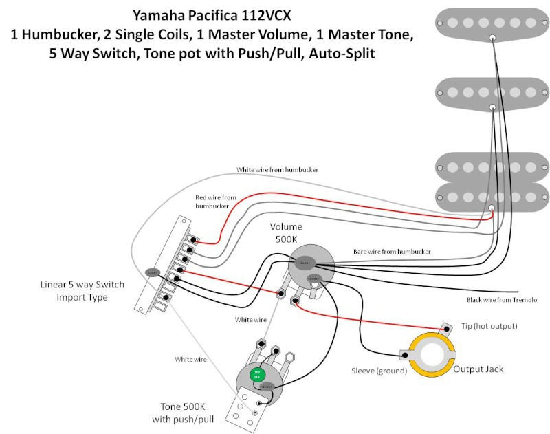 |
|
|
|
Post by newey on Dec 19, 2023 22:49:32 GMT -5
charles-
Hello and Welcome to G-Nutz2!Since you only have one HB to split, you won't need two push/pull pots. You may not even need one.  Fender has made a number of HSS Strats that use one pole of the 5-way switch to split the HB at position #2, so that you have the full bridge HB at the bridge position (Pos. #1), and at #2 you have one bridge coil in parallel with the middle- to sort-of mimic position 2 on a regular SSS Strat. They call this the "auto-split". Diagrams to do so are on the Fender website. However, you will need to translate the diagram to correspond with your import-style switch. Also, these import-style 5-way switches are not all alike. Some have only a single common terminal, some have the two commons wired together from the factory with a very tiny piece of wire. Given that your guitar is just a single V and T set-up, yours might well be one of the oddball ones- so you may need to check the switch's operations before wiring it in. If you want to have the option to split the bridge HB in either position 1 or position 2, then one of your push/pull pots can be used to do this. We have diagram(s) around here to do so, we'll point you to one if that's the way you decide to go. The coil-cut switch is effectively like a separate module that will get wired onto the HB, it won't affect any of the other existing wiring. That leaves you with an extra Push/pull pot. You could throw it into the parts bin where it will sit gathering dust until the next project, or you could go down the true GuitarNutz™ path, where more is always . . .well . . more, and use the switch to do something neat with your Pacifica. One popular option would be for a "neck on" switch, to turn on the neck pickup in conjunction with whatever is selected by the 5-way switch. This then gives you the two "missing Strat sounds", B + N and B + M + N.
|
|
|
|
Post by newey on Dec 19, 2023 5:59:37 GMT -5
Yogi B-= A tour de force on switch nomenclature. A separate thread on this topic is a good idea, before we drift to far from frequencyblue's request. As to: The way it was explained to me here, by ChrisK IIRC, inserted the word "discrete": "the number of discrete output connections a switch can have . . ." The DPDT On/On/On example thus has only 2 throws. The center switch position makes a different set of connections than are made by up or down, but they are not separate or new connections- they are not discrete connections. So, the center position is not a third "throw". At least, that aided my understanding of this topic.
|
|
|
|
Post by newey on Dec 18, 2023 5:54:33 GMT -5
frets-Did this issue ever get solved? To clarify, the issue was only at switch position 2 where the coils are split? Piezo, everything else works OK? jaymenon- Her problem was no coil splits at all, not that they didn't hum-cancel
|
|
|
|
Post by newey on Dec 17, 2023 14:33:31 GMT -5
I think I saw a mustang mod where it had the third position as a kill switch, If so I think Id prefer the positioning to be: out of phase, in phase, kill switch. If the "kill switch" is intended to be useful for the machine-gun staccato effects much loved by metal-ish players, a slide switch is a poor type of actuator. A toggle-style kill switch or a momentary-actuated pushbutton are more ergonomically-friendly choices. If the killswitch is to be mostly used for "standby" (i.e., so the guitar can be left plugged in and powered up onstage, as a backup), then the slide switch is fine. I'd say (but you do you, as the kids say) that if it's a phase switch, do phasey things with it- in phase, out of phase, and out of phase with some variation- bled through a cap, what we call "half out of phase" is one popular option. Haven't looked at it specifically but I'm pretty sure that's do-able with a 3-position Mustang slide switch. |
|
|
|
Post by newey on Dec 17, 2023 14:17:26 GMT -5
spike- Hello and Welcome to G-Nutz2!The best way to be sure that JohnH sees this is to "tag" him in your post, by using the "@" symbol in front of his username, like this: JohnH. Before we can help with trouble shooting this for you, please post a diagram of the wiring you have done. There are two possibilities: First, the changes you made to the original design may be the problem- and for that we need a diagram of what your wiring is. Secondly, it could be a bad connection (or connections), which is harder to diagnose over the web. But let's eliminate possible issues with the wiring diagram first (i.e., software issues); if your diagram looks OK then we can proceed to look at possible connectivity issues, i.e., hardware issues.
|
|
|
|
Post by newey on Dec 15, 2023 8:08:38 GMT -5
toanmasta-
Hello and Welcome to G-Nutz2!I'm not sure if we have a diagram to do exactly what you want. I didn't have the time to go through your diagram but I was questioning how that blend would work with the middle pickup selected at position 4. It may be OK, but let's get a better set of eyes on it. However, you should look at this scheme from JohnH: guitarnuts2.proboards.com/thread/8244/simple-blended-strat-series-parallelFirst, John's scheme has some good ideas you may want to consider. His scheme blends one bridge coil with the neck in series instead of in parallel. He also specifies the use of no-load pots for the tone and blend pots; regardless of the tone pot, using a no-load for the blend is a good idea to take that pot out of the circuit when not in use. But even if JohnH's scheme doesn't intrigue you, it can serve as a starting point for a diagram for you as well. Also note that, AFAIK, JohnH's scheme has not yet been built. If you are going to use it, we should probably have it reviewed first, just as a double check.
|
|
|
|
Post by newey on Dec 15, 2023 7:44:16 GMT -5
frequencyblue- Hello and Welcome to G-Nutz2!I'm sure someone can get you a diagram posted for this but it may be a few days. I'm presently pretty deep into holiday preparations and I suspect others are as well. I'm assuming these are slide switches like a regular Jaguar, right? Also, so that a diagram can be better matched to your specific hardware, there are a number of different types of 3-way blade switches. Is yours like a US-style Oak-Grigsby switch as is used on a Tele? Or, does it have a circuit board with a line of connections along the bottom (i.e., import-style switch)?
|
|


