|
|
Post by GuyaGuy on Sept 19, 2006 14:41:12 GMT -5
GG, Yes, the noise cancelling effect still takes place, just as you'd expect. what i meant was the so-called "out of phase" Strat quack. do neighboring pups get that sound if wired in series? Just kidding! ;D ;D Seriously, yes, the S&H can about cancel out any savings from using the innerweb, it will sometimes be as much as, or more than, the sales tax! And one can't ignore that instant gratification factor, can one?  And the double-sawbuck you blew on the axe? Good investment! But if you ever get to doubting whether or not you did the right thing, just remember that age-old admonition: "A thing of beauty is a joy forever!" ;D (© Holly Pitts, 1965) Good luck! sumgai no regrets on this guitar! the neck is really nice! and once the pups are in and the locking tuners arrive, i'll have about $175 invested in this thing!  i'm gonna try to get over there this evening to get the switch! |
|
|
|
Post by UnklMickey on Sept 19, 2006 14:42:44 GMT -5
 don't understand the Q's ?! don't understand the Q's ?! i thought that might sneak by ya. i won't tell ya out-right, let's see if you can connect the dots. Q,QQQ,QQQ,QQQ = 10 Q = ________ |
|
|
|
Post by GuyaGuy on Sept 19, 2006 14:44:04 GMT -5
i've corrected the drawings and added some text. i indicate polarity of the pickups with "a" and "b". it doesn't matter whether "a" is North or South, just be consistent. in the original version, the HB split switch did only that. so you have a total of 7 different sounds. position 1(fat), position 2(split), and position 4 are hum-canceling. in the "PLUS" version, i also use the split switch to introduce Bridge (a) into the combinations 4, and 5. position 4(split): Neck(a), Middle(b), and Bridge (a) is hum- reducing. position 5(split): Neck(a) and Bridge (a) is not hum-canceling. that expands the total to 9. in the PLUS+ version i use -Neck(a) and -Bridge(b) to make position 5(split) hum-canceling. unk thanks for the corrections and clarifications! once i have em all wired up i'll post some clips so you can hear the monster you've created! |
|
|
|
Post by UnklMickey on Sept 19, 2006 14:54:03 GMT -5
...what i meant was the so-called "out of phase" Strat quack. do neighboring pups get that sound if wired in series?... it's the same exact thing.............only different. seriously, it sounds quite different, because of the darkening of the overall tone. it has a hint of "quack", but it really isn't the same. i wonder if you might get something closer, if you did N*M or M*B, series OutofPhase. but then we would need to reconsider hum-canceling. unk |
|
|
|
Post by ccoleman on Sept 19, 2006 14:59:35 GMT -5
har har... ur welcome !
|
|
|
|
Post by GuyaGuy on Sept 19, 2006 15:05:38 GMT -5
...what i meant was the so-called "out of phase" Strat quack. do neighboring pups get that sound if wired in series?... it's the same exact thing.............only different. seriously, it sounds quite different, because of the darkening of the overall tone. it has a hint of "quack", but it really isn't the same. i wonder if you might get something closer, if you did N*M or M*B, series OutofPhase. but then we would need to reconsider hum-canceling. unk well, the "out of phase" sound is actually something i wanted to avoid! i toy with that sound on my 4 pup guitar but don't really find a use for it. on this lipsticker i wanted the series combos to give me some more powerful raunch. sounds like this will work just fine... |
|
|
|
Post by ChrisK on Sept 19, 2006 17:08:28 GMT -5
10 Q, 10 Q very much.
|
|
|
|
Post by GuyaGuy on Sept 21, 2006 21:31:52 GMT -5
got the superswitch yesterday so i'll try to get everything wired by tomorrow!  |
|
|
|
Post by UnklMickey on Sept 21, 2006 22:05:41 GMT -5
|
|
|
|
Post by GuyaGuy on Sept 22, 2006 0:50:44 GMT -5
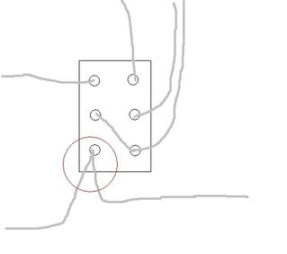 so a quick question... this is a drawing of what i think the schematic is indicating for the connections on the swtich. is that right? i'm specifically wondering about the part that's circled in red. |
|
|
|
Post by UnklMickey on Sept 22, 2006 1:00:01 GMT -5
so you're using version #3?
|
|
|
|
Post by GuyaGuy on Sept 22, 2006 1:01:13 GMT -5
oh yeah. some how i edited that out of my post.
that look right?
|
|
|
|
Post by UnklMickey on Sept 22, 2006 1:08:03 GMT -5
yes, there should be one wire from your bridge pickup and one wire that goes to the superswitch.
also, i don't know if i mentioned this:
because of the pivot on the lever, the terminal marked 5 should be the one closest to the tail of the guitar.
but the wires from the neck pickup go to that end.
does that make sense?
|
|
|
|
Post by GuyaGuy on Sept 22, 2006 1:12:01 GMT -5
yup. |
|
|
|
Post by UnklMickey on Sept 22, 2006 1:15:05 GMT -5
great.
i have to sign off for about 12hrs.
there's somewhere i have to be.
then i'll be around for a few hours, and gone for the weekend.
see ya soon,
unk
one more thing.
if you are using push-pull pots, the top of the switch in the drawing corresponds to the closest to the pickguard.
if you want the "split" to be when the knob is pulled.
|
|
|
|
Post by GuyaGuy on Oct 7, 2006 4:18:40 GMT -5
great. i have to sign off for about 12hrs. there's somewhere i have to be. then i'll be around for a few hours, and gone for the weekend. see ya soon, unk one more thing. if you are using push-pull pots, the top of the switch in the drawing corresponds to the closest to the pickguard. if you want the "split" to be when the knob is pulled. i ended up signing off for FAR longer than you planned to! stupid internet server problem, etc. plus i couldn't find a nut for my dern push/pull pot so i ended up getting a new one. bla bla bla. anyhow... i THINK i'm almost done with the wiring now. (please don't make me do that ever again.  ) but one more question... my pup is a 4 wire. i got the main lead and ground done but i'm not sure where the other 2 wires are going. at least one apparently goes to the push/pull pot. hep me? |
|
|
|
Post by UnklMickey on Oct 10, 2006 16:54:58 GMT -5
hi GuyaGuy,
been off-line for a few days, but i have little bit of time to get caught up.
the "other" 2 wires are the series-link.
they are connected together, and also to the upper left terminal of the push-pull switch.
unk
|
|
|
|
Post by GuyaGuy on Oct 11, 2006 4:38:52 GMT -5
no problem. i wasn't expecting replies on the holiday w/e! ok so they are wired together. i thought as much but wanted to make sure. hopefully i can finish this thing today! thanks! |
|
|
|
Post by GuyaGuy on Oct 13, 2006 3:54:06 GMT -5
 first time i wired it i plugged in a cable to the amp, tapped on each pup cover. each one was amplified, regardless of switching configuration. i ended up taking everything apart and going step by step again, completely rewiring the thing. same thing.  so that would mean all pups are on all the time. any thoughts as to what i'm doing wrong?
|
|
|
|
Post by GuyaGuy on Oct 20, 2006 23:48:08 GMT -5
first time i wired it i plugged in a cable to the amp, tapped on each pup cover. each one was amplified, regardless of switching configuration. i ended up taking everything apart and going step by step again, completely rewiring the thing. same thing. so that would mean all pups are on all the time. any thoughts as to what i'm doing wrong? i looked over everything and checked it against the diagram and made sure connections are secure, but it's still not right. so lel me ask you... 1. there are 4 tabs on the super switch (unaccounted for in hte diagrams). do i need to do anything with those? 2. does the 5 way itself need to be grounded? other than those possible problems, i just can't figure out what's wrong. |
|
|
|
Post by UnklMickey on Oct 21, 2006 1:45:08 GMT -5
4 unaccounted tabs? now you're scarin' me!  if they are the highest ones in the drawing above (1 on the left, one on the right, and the ones in the same position on the back wafer), then you've got a BIG problem. those are the poles, and they are of utmost importance. they correspond with the connections at the top and bottom of the switch. i just caught this before signing off for the weekend, so i won't see your reply til monday. maybe Chris or John can help you further, until i get back. cheers, unk |
|
|
|
Post by GuyaGuy on Oct 21, 2006 3:15:38 GMT -5
yup. them's the ones. i've never wired a 5-way, let alone a 5-way superswitch so i'm not 100% certain how these things work. 5-ways seem simple enough but i don't understand what connections are doing what on the superswitch. anyhow... after i posted the last time i found this diagram on the S Duncan site: www.seymourduncan.com/support/schematics/3stks4_1v_1t_super5w.htmllooks like i'm supposed to wire those 4 "unaccounted for" tabs like this then? (i'm guessing you left those 4 out assuming i knew what to do with them. little did you know how little i know...) the Duncan diagrams show pretty much the same thing on other schematics--one side grounded, the other going to the master vol. so in your diagram there's a lead going to the volume from a tab. so that means 2 leads are going to the vol pot? so just to clarify...is this what we're talking about? 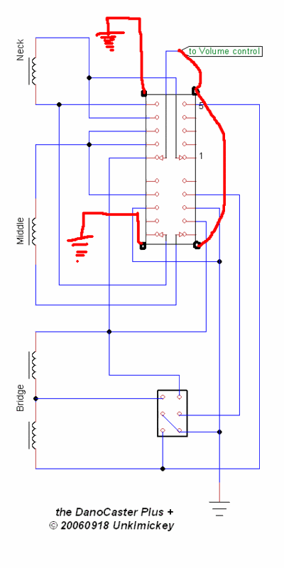 |
|
|
|
Post by JohnH on Oct 21, 2006 18:56:26 GMT -5
GG - the poles, which are the upper ones in the photo that Unk posted, are connected to red arrows on the wiring diagram (the diagram shows them currently connected to position 1), so theres no extra wires needed on the diagram. The connections for these pole-tabs are the ones shown entering the switch rectangle two at top and two at bottom.
I hope that makes sense.
John
|
|
|
|
Post by GuyaGuy on Oct 21, 2006 22:33:02 GMT -5
GG - the poles, which are the upper ones in the photo that Unk posted, are connected to red arrows on the wiring diagram (the diagram shows them currently connected to position 1), so theres no extra wires needed on the diagram. The connections for these pole-tabs are the ones shown entering the switch rectangle two at top and two at bottom. I hope that makes sense. John probably. but not to me. |
|
|
|
Post by GuyaGuy on Oct 22, 2006 18:33:07 GMT -5
GG - the poles, which are the upper ones in the photo that Unk posted, are connected to red arrows on the wiring diagram (the diagram shows them currently connected to position 1), so theres no extra wires needed on the diagram. The connections for these pole-tabs are the ones shown entering the switch rectangle two at top and two at bottom. I hope that makes sense. John like this? 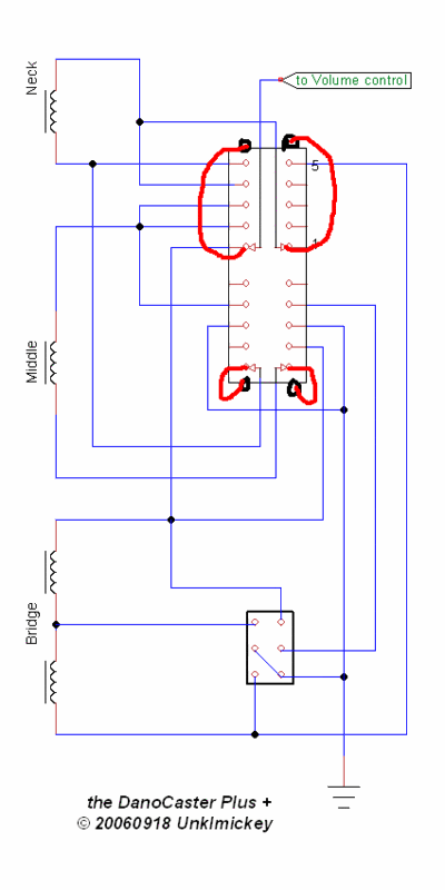 |
|
|
|
Post by JohnH on Oct 23, 2006 6:49:37 GMT -5
Yeah sort of.
Take the top left set of contacts on the diagram as an example, and ignoring the mark-up. The red arrow is shown connected to a black vertical kine, which becomes a blue line when it crosses outside the black rectangle. At the point where the blue line starts, at the edge of he black rectangle, there will be one of those four extra tabs. Thats where you connect the wire to the volume control, as shown on the diagram
Any good?
John
|
|
|
|
Post by UnklMickey on Oct 23, 2006 12:18:10 GMT -5
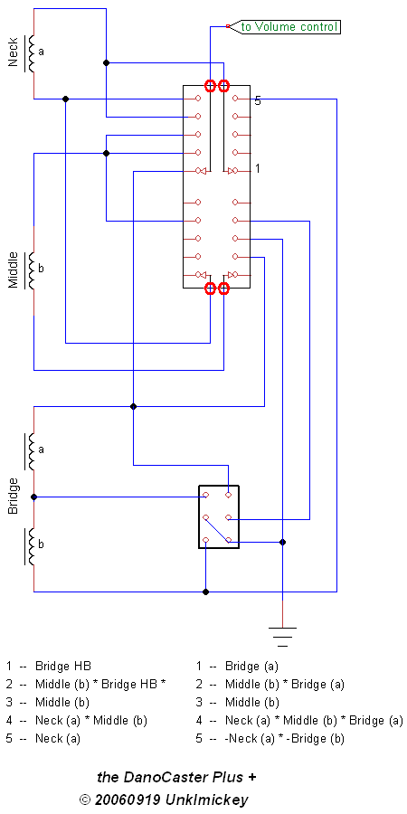 poles circled in RED. thanks for the help John. ISP problems, i've tried to post this several times, so once i'm successful, i'll quit until problems clear up. unk |
|
|
|
Post by GuyaGuy on Oct 23, 2006 18:48:30 GMT -5
OK, i got it now. i guess i just wasn't reading the diagram correctly. i thought those lines were just accidentally black. now i'm pretty sure i got it so i'll try to finish the wiring tonight. thanks again, unklmickey and JohnH! |
|
|
|
Post by UnklMickey on Oct 24, 2006 11:09:52 GMT -5
hi GuyaGuy,
we're looking forward to hearing from you after this is sorted.
looking back at the way i drew this, i am convinced that anyone who already knows how a superswitch works, would have understoond where the poles are.
but anyone who didn't, would probably make the same assumption you did.
so obviously i need to re-work my symbol to make it clearer.
sorry for the confusion.
hope it goes well now.
unk
|
|
|
|
Post by GuyaGuy on Oct 24, 2006 21:05:06 GMT -5
unklymickey, yeah, it was just my lack of familiarity w/ the switch. at least i didn't have to completely rewire. i got it all finished last night and put it together, plugged it in, and the results... good news: some of it works! bad news: not all of it! all pups are working but not all of hte switching. so i'll have to take it apart again to see what i did wrong. i'll report back....again.  |
|


 )
)


