jeremyo83
Meter Reader 1st Class

Posts: 81
Likes: 0
|
Post by jeremyo83 on Sept 27, 2006 14:20:01 GMT -5
but this time i've got the diagram all worked out myself, and I just need someone to double check all of my wiring, etc. My friend has a single HB in the bridge position, and I was thinking we could rewire it for a little more fun when he uses it. So let me know if I've got myself screwed up, or if I've done it right for once! ps.. feel free to add your opinion on whether or not there will be much difference between positions 3 and 4 (tap coils 1 and 2). and let me know if I haven't drawn something appropriately, ie: wrong symbols, etc., or if you're confused about something. 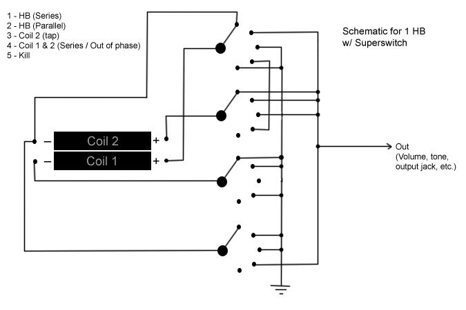 *image edited as per suggestions from ccoleman & unklmickey* |
|
|
|
Post by ccoleman on Sept 27, 2006 14:55:26 GMT -5
1) the KILL position 5 should send - AND + of both coils to ground.
2) coil 1 and 2 will pretty much sound 99% THE SAME... I would replace the COIL2 position 4 with IN SERIES OUT OF PHASE.. in other words coil1 in series with a REVERSED coil2... way more different sound.
Good luck wiring it up, and post an MP3 sample of it !!!!!!!
|
|
|
|
Post by UnklMickey on Sept 27, 2006 15:52:06 GMT -5
1) the KILL position 5 should send - AND + of both coils to ground.... be careful here CC. shunting both the coils to ground will still not connect the output to ground.that is what is needed to have a nice, low-noise kill position. Jeremy, i won't tell you exactly how to do this, but, when a switch is only used to either connect X to Y or leave them disconnected, and there is no Z it doesn't matter which one is connected to the pole. in fact it doesn't matter whether a coil is always connected to ground or disconnected from ground, when it is not being used. so using that info, you can probably figure out how to change things so in position 5, you can connect hot and ground together. if a HB is in the BRIDGE position, the coil nearest the bridge will be a bit more brittle and edgy. but, series OoP will have a much different sound. non-wiring advice: only show the poles of your switches in one position. the drawing will look less cluttered it doesn't matter which, but all of them should be in the same position. i usually use 1 or 5 on a superswitch. also, the speckles on your drawing are probably the result of converting back and forth from .bmp to .jpg if you can, use .gif to post your images, and never convert them to .jpg .jpg is great for photo images, but can uglify drawings. cheers, unk |
|
jeremyo83
Meter Reader 1st Class
Posts: 81
Likes: 0
|
Post by jeremyo83 on Sept 27, 2006 15:53:15 GMT -5
okay, i edited the diagram as per ccoleman's suggestions. I've never tried to wire anything in series/out of phase, but I think I've gotten it right (famous last words..) For that matter, I've never heard anything out of phase either, so I really have no idea what to expect. so, how'd I do? here's the image again. edit: unk, it looks as though you posted your suggestions the same time I posted by modifications.. i'll work on it and get back on it. |
|
|
|
Post by ccoleman on Sept 27, 2006 16:00:08 GMT -5
unk you're right... I left out something important on my kill switch advice !
jeremy your kill position is not working... read what unk posted above and it says exactly what is needed to be connected to what, to make it work.
|
|
|
|
Post by UnklMickey on Sept 27, 2006 16:17:29 GMT -5
Jeremy,
series OoP would probably be my preference, but...
when you actually do the wiring, turn the pickup so the single (coil 1) is away from the bridge.
if you are only going to be able to access one, this one won't sound as brittle.
|
|
jeremyo83
Meter Reader 1st Class
Posts: 81
Likes: 0
|
Post by jeremyo83 on Sept 27, 2006 21:38:04 GMT -5
okay, so the diagram has been edited in the previous posts, so i won't bother posting it again... however, I'm am not 100% convinced that I've followed your suggestion completely, although I think I'm pretty close, because I just about copied how you did the killswitch in my other wiring question. so, have I done the kill properly  killswitch aside, have I done everything else properly as well? j |
|
|
|
Post by UnklMickey on Sept 28, 2006 8:27:29 GMT -5
...so, have I done the kill properly
killswitch aside, have I done everything else properly as well?
j no to the kill switch. a qualified YES, to everything else. in position 3, you have the + of coil 1 going to ground. the - isn't connected, so the coil isn't shunted -- that's good! but you don't even need to connect the + . it won't hurt anything, but why bother adding the unnecessary wire? now to fix the kill switch! you could change things, on the second switch up, from the bottom. connect the pole to ground, and connect the - of coil 1 to the throws in positions 1, 2, and 4. that will now allow you connect the buss you have marked as "Out" , to this switch in position 5 shorting the output since the pole of the switch is grounded, the Out will be connected to ground in position 5.that will give you a nice silent kill position -- no hum or noise - just like turning the volume all the way down. this is the minimum you need to change to make it work.BUT IT GETS BETTER ! since the - of coil 1 ONLY goes to ground or is disconnected, lets see if we can just connect it directly to ground.! it's already connected to ground, in positions 1, 2, and 4, so no worries there. how about position 5? well the + coil 1 is already connected to ground in position 5, so that will shunt the coil. normally, i wouldn't like that, but first of all, this is the kill position. we aren't making any sound here, so a shunted coil won't hurt anything. besides that, we don't need ANY coils connected to any switches in position 5. so......SNIP ALL THE WIRES CONNECTED TO ALL SWITCHES IN POSITION 5. now lets see what happens in position 3! we're only using coil 2 in position 3. so if you haven't already done this, SNIP THE WIRE ON POSITION 3 OF THE TOP SWITCH. there, now coil 1 - can be connected straight to ground. the ONLY thing we still need that switch the switch that was previously connected to coil 1 - for, is the kill in position 5. (connecting "out" to ground) even if you don't post it, please do the minimum first, and keep that to compare with the "better" version. then post the "better" version, and i'll proofread it to make certain my directions were clear. then, if you are ready for the advanced course, i'll walk you through arranging this for only 3 switches. in that version, accomplish all the goals, but still end up with the 4th switch completly unused! if you're not quite ready, we can resume your training at a later date. cheers, unk |
|
jeremyo83
Meter Reader 1st Class
Posts: 81
Likes: 0
|
Post by jeremyo83 on Sept 28, 2006 11:57:35 GMT -5
okay, let's take this one step at a time.. this is just the "least amount of work" scenario. step 1 - removed wire from pole 1, position 2 to ground. okay, this is where you begin to lose me a little bit, although we'll see if I follow or not. in position 5 now, both coil 2+ and - are connected to the switch, but not to ground (directly), while both coil 1+ and - are connected to ground, creating a loop and shorting out the sound.. now for what I don't quite understand; essentially what has been changed in this diagram is only that the pole is now always connected to ground, and the coil is disconnected/connected, rather than the pole being disconnected/connected. can you explain in a little more detail the reasoning for this? I'd love to follow what I'm doing a little better... I can follow currents, but grounds (and killswitches, for that matter) seem to get me every time. how can I logically approach them better. 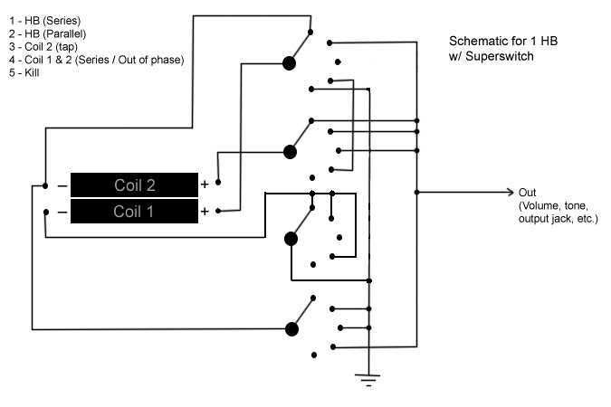 |
|
|
|
Post by UnklMickey on Sept 28, 2006 12:33:10 GMT -5
sorry J, the way i explain things, sometimes doesn't make that much sense to newbies.i didn't check what i had written. i'll edit that previous post. instead of cluttering things up with more words, here is what i meant: 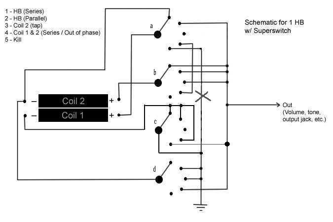 get rid of the wire marked with the "x". and add the skinny (so you would be able to spot it easily) wire. read back through my previous post. does it make sense now? i've also lettered the switch sections. you are ready to move on to the "better" version. cheers, unk |
|
jeremyo83
Meter Reader 1st Class
Posts: 81
Likes: 0
|
Post by jeremyo83 on Sept 28, 2006 14:48:37 GMT -5
okey dokey.. now that I understand that the 'kill' needs to send the "out" to ground, and not the signal from the coils, it makes so much more sense! so as far as I can tell, this is what you meant in your previous post, and now I'm supposed to be ready for the next stage ... now lets see if I'm actually ready. 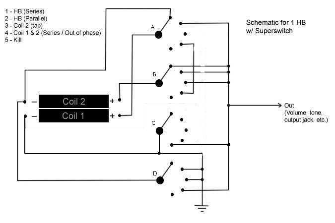 ps. sorry about the fuzziness that's growing on the image. I'm limited as far as imaging programs go at work, and it does involve switching from bmp to jpg as you guessed before. |
|
|
|
Post by UnklMickey on Sept 28, 2006 15:12:25 GMT -5
i only skimmed it, but it looks right.
also, did you notice how much less cluttered the drawing is now?
don't worry on my behalf, about the drawing speckles.
i used to hate it when that happened to my work.
if you have a really complicated "masterpiece" and want to keep it looking good, use gif instead of jpg.
i take the bitmap file i generate in paint, when i use it, and open it with MS office picture manager.
then EXPORT that as a .gif
photobucket likes either jpg or gif.
so, do you want to start the "advanced wiring course"?
unk
|
|
jeremyo83
Meter Reader 1st Class
Posts: 81
Likes: 0
|
Post by jeremyo83 on Sept 28, 2006 18:03:29 GMT -5
thanks.. I'll see if I can use office to make gif files instead. the drawing is much clearer now, and I am beginning to understand the principles of grounds/kills, and all that stuff much better. so.. advanced wiring for dummies, here i come. give me hints so i can try to work it out myself... it'll give me something to do at work  thanks unk |
|
|
|
Post by UnklMickey on Sept 28, 2006 19:18:56 GMT -5
this part really only works as a tutorial and exercise. not really a "solve this problem" lesson. you'll enjoy it none-the-less. if you look at your previous drawing, there are times when you connect things through a wire, through a switch contact, through a wire, then through another switch contact, then through a third wire finally reaching it's destination. that makes for extra soldering, and clutters things up a bit. but more importantly, if we only use one switch contact on that switch to get where where we need to go, then we have those contacts available to do other functions. we can often even free-up an entire pole. when the designs get very complicated, having an extra pole available can make the difference between getting the job done, and having to give up. your application is a good training ground for exercise. First.we always use coil 2. (except in the kill mode where it doesn't matter) so we will permanently connect one end of it to something, either Out, or ground. i've chosen ground, but since is it always used, we could just as easily chosen Out. Second.since we can now only use this coil with the - connected to ground, we can't change it's phase.that's okay if we can change the phase of the other coil, to meet the out-of-phase requirement. so we will connect each end of coil 1 to a POLE. that makes both end of coil 2 able to connect to anything in the circuit. so far we've only used 2 poles! Third:the only thing we have left to do, is figure out what things coil 2 + will need to connect to. in series (and series OoP) positions it needs to connect to coil1. but coil 1's switches will do that job. in parallel and position 3, coil 1 + needs to connect to Out. there are 2 choices, either connect coil 1 + to the pole OR connect Out to the pole. Done?:OOPS! -- WAIT! -- WHAT ABOUT THE KILL? oh, right! this design requires a kill. we don't have a switch connected to ground. so that means we MUST connect Out to the pole so we can connect to ground in position 5. DONE!:well that looks like every thing is covered, so let's see if it actually will work. i've provided the basic skeleton for this design, according to all the desicions we made. i put a buss in for coil 2 +, and left all the busses long. just erase the ends after you make all the connections. i think this will make for a reasonable drawing, but after you're done, if it looks stupid, feel free to route the lines differently if you want. try to "wire" it up according to your chart, and see how you do. good luck! 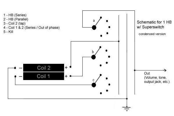 |
|
|
|
Post by ChrisK on Sept 29, 2006 9:37:32 GMT -5
One might find that series (and especially parallel) OOP within a humbucker to be exceedingly thin sounding due to the close(st) proximity of both coils. There isn't a great deal of difference in harmonic content within such close spacing, except at the highest harmonics, even at the bridge.
Series (and parallel) OOP with a neck and bridge (or at least either with a middle) pickup are the most rewarding.
Also, since the pickup in these modes will NOT be humbucking, significant high frequency interference susceptibility will occur.
(In my not so humble opinion.)
|
|
|
|
Post by ccoleman on Sept 29, 2006 9:54:53 GMT -5
I would shield it using the QTB mod (copper or aluminum foil around pickup cavity, tied to the star ground point thru a big ole 400V cap).
|
|
|
|
Post by UnklMickey on Sept 29, 2006 12:57:22 GMT -5
One might find that series (and especially parallel) OOP within a humbucker to be exceedingly thin sounding due to the close(st) proximity of both coils. There isn't a great deal of difference in harmonic content within such close spacing, except at the highest harmonics, even at the bridge.
Series (and parallel) OOP with a neck and bridge (or at least either with a middle) pickup are the most rewarding.
Also, since the pickup in these modes will NOT be humbucking, significant high frequency interference susceptibility will occur.
(In my not so humble opinion.) one might even argue that a 5-way for a single HB is a complete overkill. there is a strong argument that series/split/parallel switch, is the best choice for a single HB. still, i personally choose to leave that kind of value judgement up to the individual. given the fact that jeremy is using a 5-way, and 1 of those positions is being used as "kill" (not what i would do, but that's desireabe to him.), that leave 4 position to fill. 3 are easy choices. but what to do with the 4th one. the other single? will sound marginally different, and that margin increases slighlty, closer to the bridge. the 2 coils of a covered HB usually have a little more disparity, than an uncovered one. in uncovered pickups where both coils have set-screw pole-pieces, the coils sound almost identical. OoP?for all the same reasons that the coils sound similar, the OoP combinations will be thin and WEAK. and we have little temporal difference because the coils are so close to one another. we will have less output than a single and more hum. doesn't sound like a great choice. comparing the OoPs, Series Out-of-Phase (SOoP) is bad. Parallel Out-of-Phase (POoP).........well the acronym says it all! either of these sounds, as bad as they might be, will DIFFER from the other 3 choices. and maybe it doesn't even have to be that bad! remember, this is a work-in-progress. we have thus far, been working to use our switch contacts more efficiently. and have nearly completed the exercise, where we have totally freed-up an entire pole. so.....................with an entire pole (or even just a single throw in the right place) available, someone with experience, such as yourself can imagine what might be done, with EITHER series OR parallel OoP to make it much more useful. but, don't spoil the ending.we're still in the middle of the plot. remember Chris, there is a madness to my methods. unk |
|
jeremyo83
Meter Reader 1st Class
Posts: 81
Likes: 0
|
Post by jeremyo83 on Sept 29, 2006 15:46:03 GMT -5
alrighty.. i've been so busy at work today, it's taken me until the end of the day to make a post.. it's almost not right! anyways... I've drawn up the diagram using only 3 poles, so go ahead and proof that... 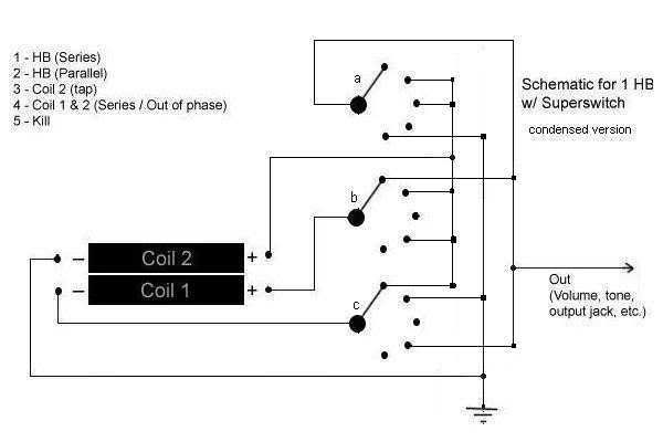 now, all this talk of SOoP and POoP (besides making me realize that I have to go to the bathroom) is making me really curious what unk has in mind for the fourth pole. also, you should know that I've taken a look at my friends guitar, and without some serious routing to fit in the superswitch, and a new pickup with four lead wires, this project won't actually be taking place any time soon... although i think he also has a tom delonge strat that we might be able to work with... at any rate, this has been (and still is) a terrific learning experience thanks to all of you. i feel a lot more confidence working with wiring and switches especially because of this community. j |
|
|
|
Post by ChrisK on Sept 29, 2006 17:01:06 GMT -5
Well, just so we don't get any POoP in the SOoP.
They DO make 2 pole 3 way lever switches (Tele)!
AND a 2 pole 4 way lever switch (Tele)!
If we loose the POoP and the SOoP, we can do series/split/parallel and still kill the bugger at will.
If we use a humbucker with known dissimilar coils (DiMarzio), we can get different single coil sounds. Zounds kids, we could do series/split/split/parallel and even still kill the bugger at will Phil with a 2 pole 5 way lever (a real one, not that Fender notch'ification transmorgafied 3 way thingy).
I have a DiMarzio multibucker that has four dissimilar coils that I wired with 8 wires for individual coil access (since it is PCB based).
I'm not sure what I should actually do with it.
|
|
|
|
Post by UnklMickey on Sept 29, 2006 17:32:56 GMT -5
...Well, just so we don't get any POoP in the SOoP... that would be even worse than having the SOoPie POoPies. |
|
|
|
Post by UnklMickey on Sept 29, 2006 17:33:22 GMT -5
...making me really curious what unk has in mind for the fourth pole.... we will get to that -- next week -- gotta leave a bit of mystery over the weekend. your schematic will function according to the table. because of the way i drew the skeleton,you made some connections to the coil 2 + buss, that i would have made directly to Out. that makes the drawing cleaner, i'll have to think if there might be a marginal advantage or disadvantage of doing the wiring that way. either way, it will still work. if you want continue a bit farther, you can. i've prepared some "homework" but it's optional. we'll get into using the 4th pole to make the SOoP and/or the POoP much more palletable, next week. and perhaps, even a possiblity or two, that i haven't yet hinted at. _______________________________________________________________________________________ More practice: We wired this for 4, of the 6 possible combinations of 2 coils. And added a kill switch. This time, use your same list, EXCEPT: position 3 = coil 2 (single), position 5 = parallel OoP. QUIZ: CHANGE the skeleton I gave you: Connect coil 2 + to pole b. Connect coil 1 + to the buss that coil 2 + was previously connected to. Everything else stays the same. (Print the new skeleton as a worksheet, but no need to post the drawings you make.) 1 -- are all 6 combos and the kill possible? 2 -- if not, which one(s) aren’t possible? NEXT This time coil 2 + is connected to pole b. Coil 1 + is connected to pole c Coil 1 – is connected to the buss. 3 -- are all 6 combos and the kill possible? 4 -- if not, which one(s) aren’t possible? __________________________________________________________________________________________ |
|
jeremyo83
Meter Reader 1st Class
Posts: 81
Likes: 0
|
Post by jeremyo83 on Sept 29, 2006 22:20:52 GMT -5
sounds like i'll have some fun doing homework this weekend if i can get around to it.. we'll see what plans my wife has... i did have some questions that i forgot to post with the diagram -- with positions 1 and 4 (series, and SOoP), I connected the lead straight to out. (b1 to out & c4 to out). I had thought about connecting them to the bus and sending them to out through pole A. I decided against this partially because of comments that you made before about going through multiple poles to get to out, but mostly because I wasn't convinced that it would actually work. Would sending the signal through the bus through pole A to out actually be series, or would it make the signal parallel? (or just not work at all?) plus, based on your last post there reviewing the diagram, it seems like the general rule is that if it is going out, just send it straight there, right? j |
|
|
|
Post by UnklMickey on Sept 29, 2006 23:00:00 GMT -5
sounds like i'll have some fun doing homework this weekend if i can get around to it.. we'll see what plans my wife has... ... this kinda homework is just for keeping busy. if your wife it willing, you should just get busy with her instead. b1 and c4 MUST go to out. if you connect b1 to the buss, the 2 ends of coil 1 will be connected together. then, connecting a1 to the buss will get you coil 2 only. same sorta story with c4. so you did the right thing with them. it would work wrong, if you did it the way you just described. in the parallel combo, coil 2 + needed to connect to Out. so the buss is connected through a2 to Out. i would have connected b2 to Out, but you connected it to the buss. it still eventually gets to Out, so no problem. i just prefer to go straight there. have a great weekend. unk |
|
|
|
Post by UnklMickey on Sept 29, 2006 23:32:16 GMT -5
...I have a DiMarzio multibucker that has four dissimilar coils that I wired with 8 wires for individual coil access (since it is PCB based).
I'm not sure what I should actually do with it. possibilities are. |
|
|
|
Post by ChrisK on Sept 30, 2006 16:30:34 GMT -5
It's currently holdong a notepad up on one of my file cabinets.
|
|
jeremyo83
Meter Reader 1st Class
Posts: 81
Likes: 0
|
Post by jeremyo83 on Oct 2, 2006 13:58:06 GMT -5
homework: 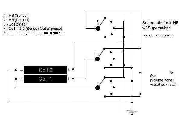 I'm pretty sure this is right. and then scenerios 1 & 2 Scenerio 1 1 - HB Series - No, only by adding a 2nd bus 2 - HB Parallel - Yes 3 - Coil 1 tap - Yes 4 - Coil 2 tap - Yes 5 - SOoP - Yes 6 - POoP - Yes Scenario 2 1 - HB Series - Yes 2 - HB Parallel - No, only by connecting bus to ground 3 - Coil 1 tap - No, only by connecting bus to ground 4 - Coil 2 tap - No, only by connecting bus to ground 5 - SOoP - Yes 6 - POoP - Yes so? ps.. no, i didn't have time to do homework over the weekend |
|
jeremyo83
Meter Reader 1st Class
Posts: 81
Likes: 0
|
Post by jeremyo83 on Oct 2, 2006 14:24:11 GMT -5
surely you can do better than that!
|
|
|
|
Post by UnklMickey on Oct 2, 2006 16:38:04 GMT -5
surely you can do better than that! NO WAY! i can't imagine ANYTHING that would be cooler, to hold up that notepad!  ________________________________________________________________________________________ regarding the homework: your answer to Questions 1&2 was good. for the HB series, either connect b1 and c1 (not the most direct), or better yet: connect b1 to pole c OR connect c1 to pole b no need to draw an entire buss, when only a single wire is needed. 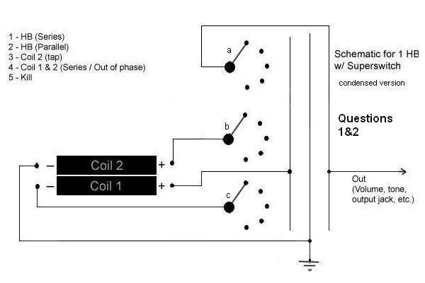 _____________________________________________________________________________________________ you should re-visit questions 3&4 using the drawing below. 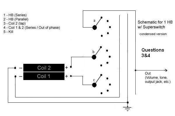 i'll be back later, or tomorrow with more on the use of the 4th pole. i need to draw some pictures to explain it all. cheers, unk |
|
jeremyo83
Meter Reader 1st Class
Posts: 81
Likes: 0
|
Post by jeremyo83 on Oct 3, 2006 9:15:09 GMT -5
you should re-visit questions 3&4 using the drawing below. okay.. I don't have a copy of the diagram i used to get my answers before, but I think it was the same... although i did get new answers, so perhaps i drew the diagram wrong the first time. regardless, these are the answers i've gotten this time around; Scenario 2 1 - HB Series - Yes 2 - HB Parallel - No, only by connecting bus to ground 3 - Coil 1 tap - No, only by connecting bus to ground 4 - Coil 2 tap - Yes 5 - SOoP - No, only by adding a second buss 6 - POoP - Yes |
|
|
|
Post by UnklMickey on Oct 3, 2006 18:57:14 GMT -5
okay Jeremy,
basically what we see in the last skeleton, is there is no way to connect coil 1 - to ground.
so sounds 2 and 3 just aren't possible.
i think you've seen enough of that kind of stuff,
to be able to work through making decision about where best to use the poles in creating a new design.
now it's on to "the 4th pole".
hang on, it's a looooooooooooong ride.
|
|


