|
|
Post by ChrisK on Dec 2, 2007 11:42:01 GMT -5
Thanks sumgai. R1500 IS the part number for a 12K Ohm 1W resistor thereon. Sorry about the links not working, I actually tested them before I finished the post (usually do, QC is). They don't work for me now, tho. Now, that would've been clever of me, eh.Would mean ,"Dang, I wish that I'd thought to design it to reuse the existing switches."  Now, that would've been clever of me, eh. Now, that would've been clever of me, eh.  Would mean ,"{wink} I was."  Yes is. |
|
|
|
Post by mr_sooty on Dec 2, 2007 15:01:18 GMT -5
Awesome, thanks guys, I will give this a go and let you know whether or not I destroy my footswitch. Nah, the existing setup is so simple I'm fully confident I can get it back to stock if it all goes horribly wrong.
|
|
|
|
Post by sumgai on Dec 2, 2007 19:02:36 GMT -5
Chris, Obviously each link depended on a temporary cookie, which won't be found on any other machine, nor on yours, after that particular browsing session. So much for the power of the innerweb. Once again, Shakespeare's monkeys strike with the most malevolent non-chalance.  As it turned out, the last few digits of each of your links was the relevant part number. I just extracted the necessary base information for sooty, that's all.  sooty, Good luck! ;D sumgai |
|
|
|
Post by mr_sooty on Dec 2, 2007 20:08:01 GMT -5
Thanks, I have the parts, about to start the surgery!
|
|
|
|
Post by mr_sooty on Dec 2, 2007 21:36:23 GMT -5
OK so, good news and bad news. The good news is, it works. The reverb one works perfectly. The bad news is that the channel one is backwards. I follwed the instructions as written, everything's the right way around - even the led's. The problem is: Light on = clean, light off = dirty. It's not the end of the world, I can probably work with that, but I'd like to get it the right way around if poss'. Any thoughts?
|
|
|
|
Post by JohnH on Dec 3, 2007 14:37:05 GMT -5
The dirty channel operates when the switch is closed, at which time the LED is shunted and goes off.
Chris - do you think it would work with the LED in series with the switch instead of parallel to it? maybe with a resistor or two in series and/or parallel with the LED to let the right of amount of current through the LED? Then the LED would be on when the switch is closed
John
|
|
|
|
Post by ChrisK on Dec 3, 2007 15:25:26 GMT -5
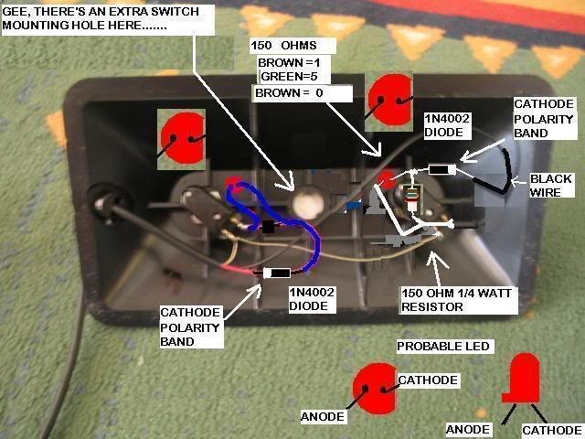
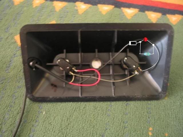
...I see said the blind man as he grabbed his hammer and saw........ I see what happened..... When you posted.... ...so the footswitch seems to actually turn the drive off, rather than on...., I took this to mean that when the switch was in the closed state, it switched the amp to clean (..seems to actually turn the drive off..). If the switch had turned the drive (mode) off "when it was switched ON", the LED would be lit in drive mode and off in clean. Things apparently work the opposite. When the switch pole is OPEN/OFF and the relay coil does not have significant current flowing thru it, the LED will be on. When the switch pole is CLOSED/ON and the relay coil does have significant current flowing thru it, the LED will be off. Semantics. I apologize for not fully understanding what you meant, but I have little awareness of this actual amp. Sooooo, To have the LED lit when the switch is CLOSED/ON, what do you think that we should do? (Hint, the other LED is lit when its switch is CLOSED/ON.) Yep, you need to wire both switching circuits the same. In other words, the way that I drew the original design was correct. --- RED WIRE-------| |Diode|----- |LED )--- Oswitch pole O----- TAN BUS WIRE (as it is now) --- BLK WIRE-------| |Diode|----- |LED )--- Oswitch pole O----- TAN BUS WIRE (as it shall be) --- TAN COMMON BUS WIRE Now, as I had mentioned, I'm a little concerned about running the LED at 30 mA. You can either do so (you did buy a couple of extra spares as I had recommended?) or place a 150 Ohm (sorry, not 12 K Ohm) in parallel with it.  |
|
|
|
Post by mr_sooty on Dec 3, 2007 15:37:43 GMT -5
So, wire the channel swith up the same way the reverb one currently is? Do I still need the resistor?
|
|
|
|
Post by ChrisK on Dec 3, 2007 16:03:20 GMT -5
No, you don't need THE 12 K OHM resistor,
but, as I state ""I'm a little concerned about running the LED at 30 mA. You can either do so (you did buy a couple of extra spares as I had recommended?) or place a 150 Ohm (sorry, not 12 K Ohm) in parallel with it."",
I'd wire a 150 OHM resistor in parallel with the LED for the clean channel to shunt about 12 mA.
If you don't, the LED may well last for a very long time anyway, but..................I can't say.
|
|
|
|
Post by mr_sooty on Dec 3, 2007 16:30:15 GMT -5
I didn't by any spares because the shop's pretty close by. I can just go back and get what I need. Could you possibly give me a part number for the 150 ohm resistor?
Also, with your new diagram, there appears to be nothing connected to the switch terminal that the black wire originally went to. Is this right? Should the LED not be connected to the other trerminal instead? The channel in the picture seems to be wired quite differently to the reverb.
|
|
|
|
Post by mr_sooty on Dec 3, 2007 17:04:48 GMT -5
|
|
|
|
Post by ChrisK on Dec 3, 2007 17:09:04 GMT -5
Oops, fixed. Aside from the "oops, fixed" and the parallel resistor, it shouldn't be. Hmm, the fact that you saw the error and suggested "Should the LED not be connected to the other terminal instead" tells me that you can now "fly". www.dse.co.nz/cgi-bin/dse.storefront/47547db200230bd42740c0a87f3306ac/Product/View/R0159Part number R0159. If you go to into the store, they should tell you what they have when you ask for a 150 1/4 watt resistor. That's why they're there. If not, smack 'em. |
|
|
|
Post by ChrisK on Dec 3, 2007 17:10:17 GMT -5
Resistors are not polarised, doesn't matter.
|
|
|
|
Post by mr_sooty on Dec 3, 2007 17:19:54 GMT -5
If you go to into the store, they should tell you what they have when you ask for a 150 1/4 watt resistor. That's why they're there. You've obviously never experienced NZ retail customer service! LOL. |
|
|
|
Post by mr_sooty on Dec 3, 2007 17:29:14 GMT -5
Just to make you even more proud, here's a version I drew and was about to post just before you corrected yours. Does this look right?  |
|
|
|
Post by mr_sooty on Dec 3, 2007 17:42:55 GMT -5
|
|
|
|
Post by mr_sooty on Dec 3, 2007 19:04:51 GMT -5
Or two 100 ohms in series to get 200 ohms? Or am I talking gibberish?
*edit: never mind, I went out and got the 150 ohm ones. Might as well do it properly.*
|
|
|
|
Post by mr_sooty on Dec 3, 2007 23:01:36 GMT -5
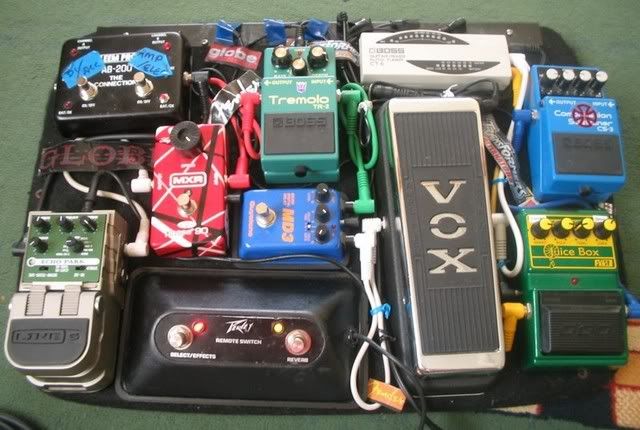
And....we're done! Here's a photo of the switch back where it belongs on my pedal board:  Work perfectly. I was a little messy with the hole drilling, but only because I was too cheap to buy the right bit! The only other negative is that the red LED is exremely bright, so now there's a risk I'll go blind as well as deaf from playing guitar, but I'll live with that. A big thanks to all who contributed their ideas, but an especially HUGE thanks to ChrisK, not just for his expertise, but also his time making the drawings, sourcing the part numbers, and answering my questions. You're a legend man. I'm really pleased to have been able to do this, an extra pleased that I won't be changing any batteries! |
|
|
|
Post by ChrisK on Dec 4, 2007 18:44:40 GMT -5
Nope, you get it. Remember that there 150 Ohm resistor?  Just solder one of those 100 Ohm ones that you have across it. More current will be shunted around the LED and it will be less extremely bright (how's that for a quantitative measure?).  |
|
|
|
Post by mr_sooty on Dec 4, 2007 21:28:16 GMT -5
OK, so another 100 ohms in parallel? Cool, I'll give it a go.
|
|
|
|
Post by mr_sooty on Dec 5, 2007 4:19:48 GMT -5
OK, I tried that, didn't work. The light wouldn't stay on cos it didn't have enough juice I guess. It it supposed to be a high intensity LED, it's OK, I'll live with it. Chopped out the extra resistor and it's going fine again.
|
|
|
|
Post by ChrisK on Dec 5, 2007 20:32:06 GMT -5
Oooook, so try 200 Ohms.  Empiracle is. |
|
|
|
Post by mr_sooty on Dec 5, 2007 21:26:04 GMT -5
Nah, that's ok, thanks man, I'm done. It's supposed to be a high intensity LED ayway. Thanks for all your help.
|
|
|
|
Post by sumgai on Dec 7, 2007 0:05:28 GMT -5
sooty, Naw, it's supposed to be capable of being used as a high-intensity LED, that doesn't mean that it has to be used that way.  Go ahead and use a resitor value that knocks down the brightness to what you want to see, the LED will live just as long, if not longer. (Probably longer than you want to use/keep that amp/switch.  ) Or you can buy yourself a pair of cheap sunglasses........ unless you're hankerin' to go see that cute little eye doctor at the local vision care center. ;D Of course, that begs the question - won't you feel kinda foolish, havin' to tell her just exactly why it is that you're goin' blind?    ;D sumgai |
|
|
|
Post by mr_sooty on Dec 10, 2007 3:17:50 GMT -5
Well I tried a 51 ohm one, to make 201, but it the LED still wouldn't stay on, just flashed. Doesn't matter really. I can live with a bright light, it's much preferable to having no light!
|
|
nomadh
Rookie Solder Flinger

Posts: 18
Likes: 0
|
Post by nomadh on Mar 24, 2008 14:22:58 GMT -5
Thanks so much for this thread and a special thank you to ChrisK for the time you put into the great diagrams you created. I got my classic 50 to work with your mods using a footswitch I got from ebay (seller mrguitar843). Great switch BTW, good price, generic, light, strong, good components. But he didn't know how to wire it for my classic so I used it without the leds functioning until I found this thread. I used your 2nd diagram but I made both switches run the diodes and resistor in series and also used a resistor on the 2nd channel as it was already included in the switch. Also it seemed I had to reverse the anode cathode of either the led or diode but I suspect either I was reading it wrong or it was marked wrong. So anyone wanting to do this play around with it a bit and I think you will love the outcome.
Thanks again and I hope the work you put into this has or will help the hundreds of people who will want to do this at some time.
See the nov30 diagram from Chris.
I did both in series like the amp channel.
PS I wanted to repost the diagram I used but I don't see a way to upload it here.
|
|
|
|
Post by newey on Mar 24, 2008 16:07:20 GMT -5
nomadh- Welcome aboard! We like new members who follow long threads, and complete their mods without any questions!  (Just kidding, questions are fine, too). To post an image, you need to treat it like a photo and upload it using one of the image hosting sites like Photobucket. The instructions to do so are here: guitarnuts2.proboards45.com/index.cgi?board=forum&action=display&thread=1114450295Make sure you resize it to an appropriate "Board-size" before posting. |
|
|
|
Post by mr_sooty on Dec 3, 2008 20:52:28 GMT -5
Just bumping this because I'm doing another one and using this for reference. It's easier to find if I bring it to the top of the pile!  |
|
|
|
Post by angelodp on Dec 3, 2008 23:32:29 GMT -5
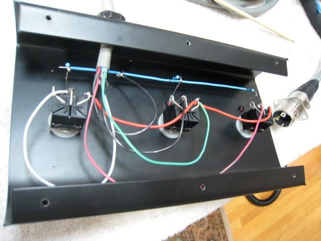
Not sure if this is helpful... but I did my footpedal for my OD amp this way. It controls, mid-boost, PAB and OD  |
|
|
|
Post by mr_sooty on Dec 3, 2008 23:57:53 GMT -5
Awesome, looks good. Yeah, I did this Classic 50 one a year ago, and now I'm doing a mates Classic 30 one. Except I keep blowing LED's on the channel select. Reverb is fine. I have the 150ohm resistor we chucked in the first one, but still blowing. Have blown two so far. I know I'm wiring them in the right way (I think), because the LED goes initially, then blows when I switch off and on again. If it was in backwards it just wouldn't go at all - right?
So maybe I just up the resistor value. I have some 51 ohm ones, I wonder if one of those on top would be enough. Or maybe 2 150 ones?
|
|