|
|
Post by warmstrat on Sept 23, 2008 16:18:50 GMT -5
I arrived here just over a year ago, looking to extend the options on my Strat. I'm very happy with what I got out of it thanks to you guys... [FULL STORY IS HERE: www.guitarnuts2.proboards45.com/index.cgi?board=wiring&action=display&thread=1598] Anyway, I'm looking for more once again. I started thinking about killswitches ( www.guitarnuts2.proboards45.com/index.cgi?board=wiring&action=display&thread=3577)... and while I'm fiddling about inside I think I'll add the treble bleed for my original mod that I left out in the beginning. So currently I have this, but without the treble bleed:  I want to add a sustainer, as made famous on these boards by 4real, here: www.guitarnuts2.proboards45.com/index.cgi?board=wiring&action=display&thread=799... and a killswitch. There are murmurs that the more complicated one's existing pickup/switch configuration is, the harder it will be to add a sustainer, as you have to unhook all the pickups' live and ground connections, route the bridge + to the sustainer circuit, and switch on the sustainer all in one go. I think (please note, this is a theory) that this switchery can be achieved on ANY guitar, no matter how complex, with a 3PDT on-on switch. Here goes.  If no-one complains about this (I *think* it's water-tight) I'll draw it into JohnH's original circuit diagram. Anyway, that's phase 1: working out how to turn the thing on. I have more ideas at the moment, but I'll wait until we (I, with your help) know if the above is even possible. Thank you all, as always, for your help and support in this field, _warmstrat EDIT: Changed diagram and switch type - after thinking about it, there was a simpler way. |
|
|
|
Post by ashcatlt on Sept 23, 2008 16:38:11 GMT -5
I think you'll want to remove the jumper, otherwise you're shorting whatever is coming out of the switch. This means you'll have to switch away from the bridge in order to make the sustainer circuit work. That is, if the bridge is selected and the sustainer turned on you'll get nothing.
Also, it only works if one end of the bridge pickup is always connected to ground. Perhaps you could use the pole that switches the sustainer power to carry the bridge ground, but then you'd have some DC across your bridge pickup. Not sure what that would do... Otherwise I think you need another pole
|
|
|
|
Post by ashcatlt on Sept 23, 2008 16:39:35 GMT -5
This is why we don't make major changes to a diagram in place. Now my post makes a little less sense. The points remain, though.
|
|
|
|
Post by warmstrat on Sept 24, 2008 4:05:15 GMT -5
Sorry, I didn't realise anyone had seen it yet  I think I solved your problems with my new diagram, yes? My only concern is that with the new switch, when the sustainer is switched off, current may still leak into its circuit from the live connection in the bottom left corner of the switch... I suppose that will depend on what sustainer circuitry I end up using. |
|
|
|
Post by 4real on Sept 24, 2008 7:13:26 GMT -5
Hey warmstrat.... I see you have started a thread after our emails... I haven't time to have a good look now, but I suspect that switch will not work...4pdt is generally required...but as I say I will need another look. Perhaps I can find some of my switch designs or that of the blueteleful telecaster thing which works well. You may have misunderstood some of the requirements... Meanwhile...I always advise not to get too caught up with the installation till you have successfully tested the device outside of the guitar, holding it above the strings well away from the pickups. To do this, select the bridge pickup...and take a wire direct from the bridge pickup to the circuit outside the guitar for testing... Most important is the circuit design is stable...on the main thread lately there has been a few things about that and can advise. On the driver the formula is 0.2mm enameled wire...thin coil (no more than 3mm deep). No super strong magnets...generally I use a 3mm ordinary steel core for stand alone drivers. Anyway good to see you are so keen, I'll look in more often, but feel free to mail me  ... Meanwhile, over at PG...the "guitar of the month" competition voting has started...11 fine and varied guitars. projectguitar.ibforums.com/index.php?showtopic=37712Obviously I have my sustainer tele in their, but I am running a bit of a drive for voting due to the number of entries...the choice is up to you...any PG members who may be here. ... Have another think about that switch (it is getting a little late just now) I have a feeling there is a fault in your plans that require another pole...will have a think about it... hmmm...a quick look seems to indicate a bunch of switches that may interfere with the switching...that blend pot for instance needs to be switched completely out...nothing but the bridge pickup via the circuit can be connected...no other pickup ground or hot. Usually the selector needs to be switched out and the bridge switched in on complex systems and 4pdt is needed. There are schemes that simply wont work without more, and that is not really practical. You will also want a dpdt harmonic switch as well. A drive control pot is also very useful though could be preset with a trim pot at a pinch. This will further complicate controls (on a strat usually a spare tone is used...but you don't appear to have one!) As I say...late and brain not functioning...sleep time! pete |
|
|
|
Post by warmstrat on Sept 24, 2008 7:32:55 GMT -5
If you take a close look at my switch you'll see that: > The left-hand set of terminals disconnect EVERYTHING when the switch is switched on. > The middle three terminals send a signal from the bridge (spliced away before the bridge signal encounters any switches) to the sustainer, and; > The right-hand three terminals switch power to the sustainer on or off. Not so? EDIT: I appreciate your concern that I should worry about the dsign of the circuit and driver and such first - but I'd like to know if the switching is even possible before leaping into the lurch.  |
|
|
|
Post by ashcatlt on Sept 24, 2008 7:37:31 GMT -5
Sorry, I didn't realise anyone had seen it yet I think I solved your problems with my new diagram, yes? My only concern is that with the new switch, when the sustainer is switched off, current may still leak into its circuit from the live connection in the bottom left corner of the switch... I suppose that will depend on what sustainer circuitry I end up using. No, I don't think so. You removed the jumper (which nobody else has ever seen), but you're still shorting the output when the sustainer is on. If the bridge pickup is selected before this switch, it will be shorted too, and the connection at this switch will not fix that. You also have not yet adressed the concern that the bridge - wire could be anywhere, and in your scheme is only connected to ground in certain settings. You will need to switch both ends of that pickup on this switch somehow. I wouldn't worry about signal "leaking" into the sustainer circuit. It won't be amplifying anything without a battery power. Depending on the circuit, you may be loading the pickups unnecessarily, which could lead to tone loss. |
|
|
|
Post by ashcatlt on Sept 24, 2008 7:40:08 GMT -5
If you take a close look at my switch you'll see that: > The left-hand set of terminals disconnect EVERYTHING when the switch is switched on. Not so? Ninja'd again! Stop doing that! Who could expect me to be up this early? This is not so, though. The left-hand set of terminals connects the everything to ground. |
|
|
|
Post by warmstrat on Sept 24, 2008 7:43:47 GMT -5
Ok, I can't think clearly anymore today. Let's see if 4real can show us his way of doing it, once he's had his sleep (hint hint)... Or if anyone else can see a clear way of achieving it (with the minimum of switch terminals)... any and all help would be appreciated. I'm still very new to the idea of sustainers, so bear with me. |
|
|
|
Post by warmstrat on Sept 24, 2008 7:45:37 GMT -5
This is not so, though. The left-hand set of terminals connects the everything to ground. Yes, that's what I meant. Sorry. |
|
|
|
Post by warmstrat on Sept 24, 2008 8:53:11 GMT -5
Sorry, I think I should have replied properly earlier. Perhaps I can find some of my switch designs or that of the blueteleful telecaster thing which works well. Yes please. That would be much appreciated. hmmm...a quick look seems to indicate a bunch of switches that may interfere with the switching...that blend pot for instance needs to be switched completely out... Yes, my design for the 3PDT does that. nothing but the bridge pickup via the circuit can be connected...no other pickup ground or hot. Again, I think I've got that right... ? A drive control pot is also very useful though could be preset with a trim pot at a pinch. Is the 'drive control' the same as the 'gain' in, say, the fetzer/ruby circuit? Is this not the same as the 'sensitivity' control which you said could be done away with? However, I remember you writing somewhere about a drive control that produced howling feedback (you described it as very 'Steve Vai') ... Can you please clarify the difference, if any, between these controls? This will further complicate controls (on a strat usually a spare tone is used...but you don't appear to have one!) As it stands, I never use my tone pot - it sits on 100% at all times. Unless the use of the sustainer may require me to tame the treble (will it?), I'm considering removing it altogether, as it's simply a waste of space. The phase switch beneath it could move out to another (smaller) mini-toggle. I'm probably going to swap the blender for a SP3T on-off-on switch as well, as I never use anything but the extreme settings on it... even more free space! |
|
|
|
Post by ashcatlt on Sept 24, 2008 12:47:50 GMT -5
I thought I had found a way to do it with just 2 poles, but there was a fatal (well, mildly annoying) flaw.  I think, though, that this accomplishes it on three poles.  Signal Send is the "hot side" of all pickups after all switching/blending/etc, maybe before volume/tone. Signal Return is the other end of all pickups, after all switching/etc. Bridge + and - must be split (as you know already) from a point prior to any switching. Hot Out goes eventually to the jack tip, possibly by way of master V/T controls. Ground is the ultimate ground point of the circuit, eventually the jack sleeve. You will have to design the sustainer circuit around the fact that you're disconnecting the DC - from ground to turn it off. This shouldn't be too hard. Edit - Couple things about this. 1) If any of your pickup selections short across the bridge pickup (yours doesn't appear to), you'll get nothing out of the sustainer in that position. 2) The sustainer input is always connected, this could cause loading related tone loss. It should be fairly easy to design it to have a very high-Z input, like 10M or so, which would alleviate most of this problem. |
|
|
|
Post by warmstrat on Sept 24, 2008 13:47:45 GMT -5
Does this switch of yours take into account that the ground of the guitar and the ground of the circuit are two separate things? I get the idea (again, could be wrong) that they should be kept separate... just instinct, I suppose. I think that it would work... But I don't quite understand all of your logic. If the bridge-, signal return and ground are all going to ground eventually in any case, why not do it in a simpler fashion? Before this switch, the bridge- is quite happily going to ground in any case, is it not? Why do we need to send it to ground again with the 3PDT? The same applies with the signal return - It's already heading off to ground as it is... Perhaps we are envisaging this switch in different places in the circuit? I've PM'd JohnH asking him for a copy of the original diagram that I will be able to edit neatly... That might make it easier for us to get our ideas across, yes? Thanks for all your effort thus far... (and keep it comin'  ) EDIT: To answer your questions/concerns: 1) As you say, doesn't appear to be a problem. If you missed something, I must just remember to check the switch before activating the sustainer. 2) Uhm... yes. You're right. I'll work out the details of that when I'm closer to that point |
|
|
|
Post by ashcatlt on Sept 24, 2008 15:45:50 GMT -5
I'm thinking the ultimate ground for both the pickups and the sustainer circuit should be the same. It'll probably require a careful look at the sustain amp circuit to make sure this part of the switch works correctly
I thought you were looking for a switching scheme that work for as many possible pickup selection configurations as possible. Aside from the case where the bridge pickup is shorted, I think I've accomplished that.
Your scheme does not have the bridge always connected to ground. Seems to be dependent on the position of S2 and the Blend pot. Again, since I'm trying to accomplish this regardless of the rest of the pickup circuit, it is not safe to assume anything about the where other switches send the signal returns. Plus, if we do in fact have to lift both ends of all other pickups (I'm not sure why this would be, but I trust that 4real knows what he's talking about here) you can't accomplish that if the signal returns are permanently connected to ground.
|
|
|
|
Post by warmstrat on Sept 24, 2008 17:36:52 GMT -5
I'm drawing up my ideas so far with ashcatlt's 3PDT switch design.
It's taking a while.
Should by done by tomorrow, it's late and I'm off to bed.
|
|
|
|
Post by 4real on Sept 24, 2008 18:23:27 GMT -5
ohhhh...only 5 hours sleep and a busy day...
of course in all kinds of time zones so bear with me...8 hours or less say...very busy day (morning here)...
I still think there are some problems and over complications...
is there a reason not to use a 4pdt switch if it provides a solution?
...
Anyway...I should have a diagram somewhere or draw it up. I spent ages in front of a TV working on different kinds of things...some complicated schemes seemed to take more poles even...
....
The more recent version still seems to have some problems...not sure, but when I draw something up, you might get a better idea of how it works...you might have to check your custom wiring as to what might happen with the other switches down the line...
My more promising approach is to use an "exchange" principle where you disconnect all switches, etc at the volume pot and reconnect with the bridge pickup. I leave the sustainer circuit in place in parallel with the bridge pickup...there is no need to switch the circuit in and out...
....
There does seem to be a fatal flaw in the last drawing at a cursory glance...
the top poles have the bridge- connected (right) to the battery...that's fine, but when off (left)...it connects to the bridge pickup hot...this shorts the bridge out regardless of any selection when the device is switched off...or so it would seem in my bleary state.
...
You are right though to plan to see if it is indeed possible and as I have a project on the go which has all these kinds of problems...I of course am keen for you to solve them for me!
....
Sorry no time right now...but I will return...
pete
|
|
|
|
Post by 4real on Sept 24, 2008 20:45:36 GMT -5
OK...just a few secs to get you started... 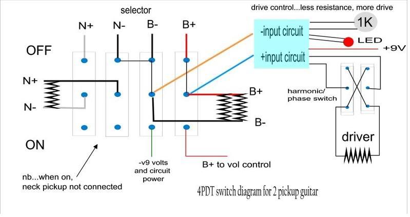 The above was a diagram of the telecaster switching (don't forget to vote in GOTM...it's struggling against a metal machine....eeekkk!) Anyway...the above diagram... the two poles on the left disconnect the neck pickup. On a more complex guitar you would be best to disconnect (lift) the selector and all switches entirely...if that makes sense...so the neck +/- would be selector signal or what have you... The bridge are permanently connected on the right set of poles...when down the bridge hot goes direct to the volume control regardless of the selector so if the other pair are used to switch it out, you still have the straight bridge pickup. The switching to the -9ve results in the circuit coming on. At first it may look as if the neck ground is still connected but in fact it is connected to the lower unconnected poles. In case of trouble, these poles could also be bridged or connected with a load (resistor) cap or diodes that may help. This works well on the tele and while there is still a potential off pop...if switched while the guitar is making a noise, there is no audible switch noise (see the audio clip which was done in one take clean and direct and the sustainer switches used frequently). ... The only reason I can see to avoid using a 4pdt is if you could get it down to dpdt and allow the use of a pp pot or something...unfortunately, try as I might I have not come close to that...it is like doing sudoko except you cant check the answers without building it. I personally try and avoid posting things that are incorrect and the big sustainer thread is full of such things. ... On the circuit...people have had success with the fetzer/ruby thing...personally I don't like the fetzer and the ruby has problems in this application. However, it does work and I have posted the suggested mods I use recently over there to stabalize the ruby part for high gain demanding application like this with 2 more components or something. My new circuit has a different functioning drive control...so ignore that 1K pot in the diagram. Typically, people use a trim pot on the LM386 pins and use something like a 10K for gain into it for sensitivity... ... ok...better run away...but this might help a bit understanding how it fits together and one known solution to get you started... pete .... I don't know what happened here...but these were from the orignal sustainer strat from years back...I think I improved things a little since then... 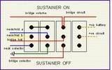 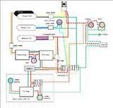 |
|
|
|
Post by ashcatlt on Sept 24, 2008 23:42:50 GMT -5
ohhhh...only 5 hours sleep and a busy day... is there a reason not to use a 4pdt switch if it provides a solution? I'm just playing around trying to do it with as few poles possible. Thought I had it on a DPDT, but it weren't quite right. Now if one could stand to leave the sustainer amp on at all times... I know you're sleepy. My switch flips up and down. Sorry about any confusion. |
|
|
|
Post by 4real on Sept 25, 2008 1:35:46 GMT -5
Still doesn't look right to me...maybe though...yeah, maybe nor I have the orientation...I am just not sure that it is selecting the bridge pickup regardless of selector position...it is the labels I think...maybe...where do the signal send and returns come from, the selector out? As for the sustainer being connected...when there is no power the circuit will not load it as the input impedance is pretty high (depending on the circuit design) and I have heard no audible change from it being connected in parallel...your idea may be better though... If it works...it could be really good as that means an extra pole from a 4pdt could be used for any complications from more complex wiring. Sorry for being so vague at the moment...a lot of things on my plate! pete |
|
|
|
Post by JohnH on Sept 25, 2008 4:55:24 GMT -5
Can I have another clue please? what are the things that really have to be switched to make it work? Can you leave the pickups to be selected by the existing wiring scheme, or do you have to force just one pickup to be active and suppress the others? Can you use the same pickup combo to give input to the sustainer driver that you also use for sound output, or do they have to be seperate?
cheers
John
ps my main interest is to guard against unintentional discombobulation of one of only two Strat Dual Sounds known to Nut-kind.
pps Intentional discombobulation is of course understood and encoraged
|
|
|
|
Post by ashcatlt on Sept 25, 2008 12:25:28 GMT -5
JohnH, this part has been discussed in other threads, but never mentioned on this particular one. The sustainer driver itself puts out a whole bunch of EM radiation, which can (apparently, I've never heard it) induce horrible noise if the pickup we're listening to is too close to it.
We're trying to idiot=proof the wiring a bit. To make sure that if the sustainer is on, only the pickup furthest from it can ever be selected. Since the driver works best at the neck pickup position, we have to make sure that only the bridge pickup is active regardless of any other selection scheme on the guitar.
|
|
|
|
Post by 4real on Sept 25, 2008 14:49:18 GMT -5
Yes...discombobulation...I think I am suffering from that... All pickups except the bridge pickup need to have both the ground and hot lifted...not just de-selected or shorted. So you want a switch that will - bypass all pickups (completely)
- select the bridge pickup
- turn on the sustainer circuit power
ashcatlt's is interesting in that it appears to be switching the circuit in and out over concern for loading, however with a good circuit design, I have never experienced loading and so have wired the circuit in parallel with the bridge pickup permanently. ... The switch looks ok on reflection...in fact...if you were to connect the -9v to the -bridge pole, and the -bridge to the centre ground connection and ground...would that do away with the right set of poles allowing a dpdt to be used? I am still a little unsure about things like the send and return labels and perhaps need to see it in a more complete diagram (if not so complex as the warmstrat specific one)... As I say, perhaps a little discombobulation of the mind on my end... pete |
|
|
|
Post by JohnH on Sept 25, 2008 15:43:46 GMT -5
OK thanks. One issue then with the Dual sound wiring is that the Bridge pickup is not always grounded. In the series setting, it is ground-neck-bridge-middle-out. You could rewire it so that bridge is next to ground. If you do that. then I could see 3 poles working, one on the volume pot hot lug, one on the bridge output and one for the battery, provided the input to the sustainer is high Z and always connected to the bridge hot. I dont see a way with just two poles, without leaving ungrounded dangling bits of circuitry hanging about (nasty).
John
|
|
|
|
Post by 4real on Sept 25, 2008 16:19:58 GMT -5
Different configurations and guitars seem to have different effects with the sustainer. The problem seems to stem from the sustainer coil generating noise in adjacent coils (pickups) through magnetic coupling (much like a transformer) and in many cases even if only one side of the coil (say the ground) is connected, some noise or oscillation is likely to occur.
As a result, both hot and ground tend to require lifting.
Also, the harmonic function works by reversing the phase. This can be done with the driver itself and so not affect the guitar's wiring...but the same effect is produced by a phase switch on the bridge pickup...something to watch for...but not apparently a problem in this case.
This is good progress (of course the proof will be in the results) and I am grateful as I largely work in a vacuum. Also, installation problems to me are the more difficult and less worked part of the project. Many use a single pickup guitar so installation only requires power (spst) while in general people don't do many installs so the solutions are rare and specific.
Thanks for giving this a go and working through it...
Before working designs for circuits, I might have some tips there too...a clean non-loading preamped LM386 circuit is sufficient but all precautions recommended for internal oscillation prevention sould be employed. I have found a low 100uF output cap to give the best results and sound.
pete
|
|
|
|
Post by warmstrat on Sept 25, 2008 18:46:03 GMT -5
I'm going away for four days now, and will be without internets - can we put this thread on ice for the moment? Unless... *grins* I started tweaking JohnH's original diagram some time ago but haven't gotten very far at all. If someone has some time to kill and feels like helping out poor ol' me... We (yes, we...) could modify the dual-sound diagram so that > 'the bridge is always next to ground' > the phase switch phases the bridge pup instead of the neck (either way, I'm unphased (lol) but if it means we can have one less switch on the guitar I'm all for it) *> the blender is replaced by a 3 pole on-off-on switch > we add a killswitch right at the end, after the sustainer and everything... I'm, ah, mostly talking to JohnH here, I think, as he knows this setup best... but anyone who has some time to kill and feels like helping me out will be greatly appreciated. Oh, and, i just spotted this from JohnH: That was my original mistake, if you look at the beginning of all this - you need to disconnect both the hot and the ground after all switching and (it appears) leave them hanging on the switch there, to avoid unnecessary noise. Looks like 4 poles is the minimum... *Obviously we will have to make sure that this phasing of the bridge happens after an un-phased signal has gotten to the sustainer circuit, (otherwise no phase reversal will occur) but before the bridge signal is split off again (to the existing selectors and the new 'sustainer' switch) Thanks again... P.S. No obligations with that diagram drawing. Only if you really want to. I really should learn the hard way and do it myself... but... |
|
|
|
Post by ashcatlt on Sept 25, 2008 22:28:34 GMT -5
Well, 4real's post above has me wondering why exactly I decided I couldn't do this with a DPDT. I think you move the Batt- over there to where the Bridge- hits, and eliminate that whole pole. Now we're into push-pull territory. I don't see any reason you can't move the sustainer input up to where the Bridge+ is, if it makes you feel better. (if) Any loading would be applied only in the selections where the bridge is included. Mine applies the (questionable) load of the amplifier across all possible pickup selections, which I think of as preferable. This way we know what we're gonna get, and won't have any unexpected tone changes with different selections. Aside from some misunderstanding about what I'm doing, I can't figure out why my switching won't work without other changes to the original schematic. The only problematic switching scheme I can imagine would be the one where some selection or other shorts across the bridge coil, like perhaps sumgai's version of the tele 4-way (a few posts down). Maybe I'm missing something in this scheme. JohnH, does it require shorting of the bridge? The kill switch in general is easy. We talked about this just a short while ago. Do you want the strings to continue sustaining while the output is silent? Edit - Oh crapitoodilly! There's all kinda bridge shorting going on there. Aw well, I tried. I've decided it can be done with DPDT on many guitars if we pay careful attention to the amp circuit. |
|
|
|
Post by warmstrat on Sept 26, 2008 0:46:34 GMT -5
Last post before I go... bags are packed and waiting... Do you want the strings to continue sustaining while the output is silent? Yeah, that was my idea. Also, on the topic of switches - I'm not obsessed with using as few poles as possible. I'd rather have better functionality than sacrifice some to make the switch tiny, if you get my point. Forcing it down to a push/pull will only be relevant if I end up using a drive/sensitivity control on the sustainer - and so far, the drive control has, I believe, been deemed unnecessary by 4real. Enjoy the boards without me... *sniff* See y'all on Tuesday. |
|
|
|
Post by ashcatlt on Sept 26, 2008 8:55:22 GMT -5
I remember now why I couldn't do it on 2 poles. If the battery - is always connected to the bridge -, then the sustainer would fire up in most (if not all) instances where the bridge is selected, regardless of the position of this switch. A capacitor in series with the bridge - at this switch would alleviate that issue, though you'd have to be careful about value selection, as it would act as a hi-pass filter.
|
|
|
|
Post by ashcatlt on Sept 26, 2008 9:34:24 GMT -5
I guess I won't get back to sleep till I type this. The easiest kill switch is an SPST which shorts the jack, tip to sleeve. It is also forced to short across all pickups selected to go to the jack. This works fine for most guitars, but it won't work with the sustainer. At least not if you want it to keep sustaining while silent because if the bridge pickup is shorted, the sustainer input goes silent. 4real, this might be the answer to your question from a little while back. You mentioned that turning the volume down didn't kill the sustainer. This is because, if you've got the volume wired like normal, it's shorting the jack, but leaving the full resistance value of the pot across the pickups. It doesn't short them out. So the sustainer kill switch needs to be an SPDT wired like a standard volume pot with pickup hot on one outside lug, jack tip on the common, and ground on the other outside lug. That should work. Don't know why I didn't see that sooner. |
|
|
|
Post by 4real on Sept 28, 2008 16:58:29 GMT -5
Yes...a spst normally open switch is typical for a push button version though so that could be tricky to arrange. I have been too lazy/unmotivated (as I really don't have a particular use of it) to address my click and non-sustain problem on my guitar...yet...but it uses such a switch.
I was thinking that switching a 500K resistor to ground instead of a direct short might be the answer...but as I say...not a lot of thought nor effort at this stage...
...
The sustainer is a tricky project...there always seems to be something different to overcome or work around in each one. With every project like this more and more solutions are added. There will be some tricky things I predict before this is over, but already the GN2 brains trust seems to have engaged in ways that look really useful and innovative...so everyone wins!
I personally have a strat project to which I am likely to use ChrisK's series parallel superswitch schematic along with a sustainer and a piezo thing too...so I am taking a particularly special interest in this...hehehe No kill switch on mine, but I suspect this is the leastof the problems that might be encountered...
By now...I am a little jaded and inactive so it takes a project like this to keep me interested...
looking forward to more...
pete
|
|


 )
)
