|
|
Post by angelodp on Sept 29, 2008 22:34:00 GMT -5
I recently made a copper faraday box for my dano and star grounded the wires. it plays well and quieted up a bit. i just checked the output of the single pickup and was shocked to see a reading of from 50k to 100k depending on the tone switch??? these pups are normally in the 4-6k range. i must have wired something wrong here. i will post befroe and after pics and diagram and if you can straighten me out on this... much appreciated. I moved the pups signal wire to the spot between the the two caps as thats what i found on a site purporting to be the original wiring. I also star grounded it all and built the copper box. The tone switch now actually works but these extremely high ohm readings have me concerned. Here is the current wiring - and original below 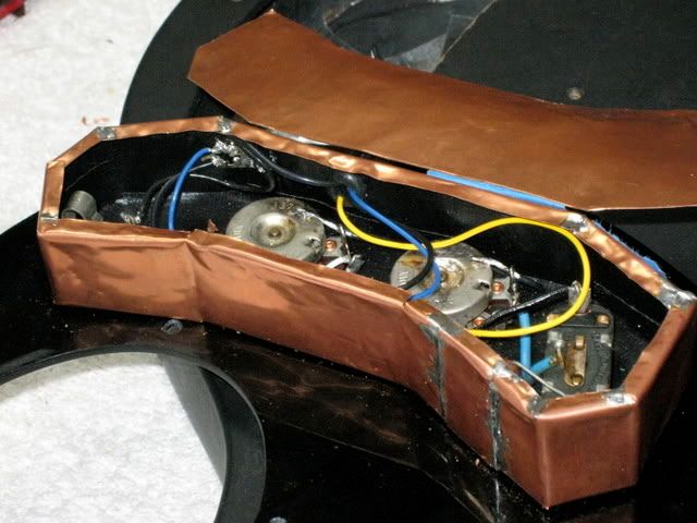 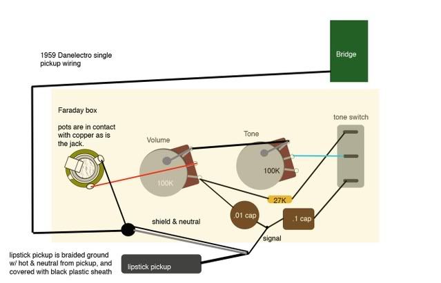 Here is the original 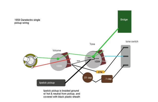 |
|
|
|
Post by ChrisK on Sept 29, 2008 22:55:13 GMT -5
These wiring diagrams are huge. Please reduce the horizontal resolution by a factor of 2. First, you are not checking the output of a pickup, but the resistance of its coil and all connected circuit components. Indeed they are. Since you have the pickup capacitively coupled to the circuit, you are measuring the volume pot and/or, depending on the tone switch, the tone pot/resistor as well. The one thing for certain that you are not measuring is the (DC) resistance of the pickup. A capacitor appears to be an open circuit at DC  |
|
|
|
Post by angelodp on Sept 29, 2008 23:20:50 GMT -5
Ok, I see.... ( man how little i know ) ..... so inside when I read the hot wire from the pickup to ground i do get 3.6 ( normal )..... Its just that when i am reading at the jack the additional values of the caps and resistor... is that right. Is my wiring OK??
ange
|
|
|
|
Post by ashcatlt on Sept 30, 2008 13:46:23 GMT -5
It's a little weird, but then I can't see any reason you'd need two caps in there unless you either wiring it the way you've got it, or switching between the two. The combined series capacitance there is within the tolerance of the smaller cap.
As you've got it now, you'd ought to be getting a low frequency roll off through the ".01 cap", and you'll get high freq roll off when the switch is flipped toward the other cap. The resistor (I think) helps to limit the impact of the tone control settings when the tone switch is "off".
I'm trying to get an idea of how this would actually affect your tone, but I need to know more about the caps. As in, .01 what?
|
|
|
|
Post by ChrisK on Sept 30, 2008 14:22:36 GMT -5
You must have meant nominal, normal is much too formal (for guitar nuts). Yes, 3.6 K (or 3 K6 in the European style) Ohms (3,600). The "K" is important, it only indicates a multiplier of 1,000. It's also important in helping to keep the units straight. Well, resistor and pot(s). The caps should (and do) read as infinite Ohms (no units necessary  ). Based on what you've indicated, if it "sounds" OK to you, it must be OK. I think that the second drawing is mis-drawn or erroneous. The first drawing supports what is being measured with the ohmmeter. The 0.01uF cap is a fairly normal value for a series (high pass) filter with passive pickups. It is needed here since the pot values are low (100K) and "suck tone" in the form of high frequency loading (the harmonics are the first to go under generator (a/k/a pickup) loading). The tone circuit either resistively loads the pickup in the form of an additional parallel 127K to 27K Ohm load, or a 100K to 0 Ohms in series with a 0.1 uF cap load, both for effective, but different high frequency cutting. In summary, the 0.01 uF cap (high-pass filter always in-circuit) helps offset the "succulent" nature (high-frequency loading) of the 100K pots and the 0.1uF cap. But, Dano's have their unique tone and they are what they are, and are loved by many. While I don't have a Dano (other than in SW models), I do understand what this circuit is doing, and have no issues with it. If the tone is of your liking, then your wiring IS correct. |
|
|
|
Post by angelodp on Sept 30, 2008 20:38:55 GMT -5
Hi, the second drawing represents the condition that i found the guitar, lo some 30 years after i acquired it. I did not think to look inside and had little experience with electronics. While the guitar played with the 2nd drawing wiring, the tone switch did nothing. The first drawing then represents my attempt at getting to the original wiring ( Dano/factory ), of which I am still uncertain, as Dano original wiring diagrams or pics are scarce. I do think that the first drawing must be close to the " real " deal as the tone switch now works and has that classic Dano sound.
So when I read 100K ohms ( reading a short 1/4inch cable ), please expand on exactly what that represents, and thanks for the education.
best Ange
|
|
|
|
Post by ashcatlt on Sept 30, 2008 23:03:45 GMT -5
Your meter sees the circuit ending at the capacitors. Those caps and everything beyond them don't exist in these measurements.
When you measure 100K, it means you've got the tone switch flipped toward the capacitor, and the volume at 10. You're measuring the full resistance of the pot.
When the switch is flipped toward the resistor, you will be measuring the volume pot in parallel with the resistor in series with the tone pot. That is (using the notation we use around here for combinations of pickups) you've got V+(T*R). The actual math looks like this:
Resistance read at meter = (V(T+R))/(V+(T+R))
= (100(100+27))/(100+(100+27))
= 55
But don't forget the K's, you know... Also, allow for the tolerance of the components.
|
|
|
|
Post by ChrisK on Oct 1, 2008 13:46:26 GMT -5
Yep (well, 56K). Decimals are like cattle and kittens; sometimes ya gots to round them up! ;D ;D |
|
|
|
Post by angelodp on Oct 1, 2008 15:53:00 GMT -5
My thanks for the great info.
ange
|
|


 ).
).