bwps
Meter Reader 1st Class

Posts: 52 
Likes: 0
|
Post by bwps on Feb 10, 2018 9:26:48 GMT -5
bwps,
I think you're OK to build your own piezo-saddle designs for retail sale, that is as generic as winding a coil of wire around one or more magnets. However, specific methodolgies and/or work processes might have been patented. Best to do a patent search first, just to make sure that you aren't taking a long walk off of a short pier.
But when you say, in public print, that you are going to analyze the Graphtech Acousti-Phonic module, you might be setting yourselves up for some tears, the legal kind. To avoid that potential, I'd suggest that you do two things:
a) Buy, at retail, a similar module from each of the other companies that make these things, as many companies as you can find. I know of L.R. Baggs, Fishman, Graphtech, RMC, Fender/Roland, etc. but there are plenty of others to scope out. The reason for this is two-fold, which brings us to:
b) Analyze every one of them, not just one or two, for frequency characteristics. One, you'll not be stuck with the results of just one particular device, and two, you head off any accusations of directly copying a specific unit. A copy does not need to be built exactly like the original (same p.c. board, same components, etc. which is a clone), it need only produce the same results from a similar input - that's what gets many small-time builders* into trouble with the big boys. Moreover, by having a compendium of results to draw from, you can devise your own set of "best sounds", and market them without fear that one of the aforementioned big boys will come after you - you've taken steps to avoid producing the exact same results as their stuff, for just that reason.
And just to make it three things:
c) Take notes. Take copious notes. Take 'em and make copious copies of those notes, and store them in different locations. Many a battle plan has been sunk before even launching, due to someone forgetting to document his/their history as it happens, only to have an accuser later say that you're simply making up excuses as you attempt to defend yourself. IOW, make almighty sure you have a squeaky-clean paddle when your accuser places you in a particularly odious creek. 
Bottom line: IANAL**, so seek legal advice on your own before you even think of sitting down to write a business plan to take to the bank for a loan. Failure to do so is on you, no one else. 'Nuff said.
sumgai
* As noted, by small-time I don't mean guys who are hacking together a system for their private use, I mean those who are doing it for monetary gain of any dollar amount.
** But I play one TV. 
Thanks, man. Your damn as hell right. "Copious copies.." lol even Seinfeld couldnt have thought of better word trick.
I have done some research and here in my country any similar fashion piezo patent has been requested. So, I can, in legal terms, move on.
We think the preamp is very good, the tones are fantastic, but needs a bit of some tweaking here and there. And copying only will not satisfy our needs. Getting the most of the already existing stuff is what will make a difference. We are making our project. However, going down in history shows us everything has been passed down. The details and processes, on the other hand, are the guys who differ from one project to another. John's preamp has that acoustic element the others so miss. We dont want to miss that.
We are thinking of for sure doing our own thing, but in a very shy and friendish manner, just for the musicians we know around the corner. If ever some success comes up along the way, we cant forsee it for the moment.
What is now drivin me nuts is if is really necessary to match the piezo's to the guitar's resonance frequency or if that is all about how the preamp circuit is carried out in terms of eqing.
|
|
bwps
Meter Reader 1st Class
Posts: 52
Likes: 0
|
Post by bwps on Feb 10, 2018 9:29:44 GMT -5
Good luck with your project. I don't know about legal issues, but id expect there is no problem building anything for private use, and also Id expect that the idea of a piezo pickup is generic enough that no-one could complain if you sold them unless you steal someones commercial design. You are welcome to adapt and use my design in any way you like, but note that it was just hacked together out of parts that I had and could understand. I'm sure there are better ways. Thanks JohnH. We are on the way there. |
|
bwps
Meter Reader 1st Class
Posts: 52
Likes: 0
|
Post by bwps on Feb 10, 2018 14:30:13 GMT -5
Good luck with your project. I don't know about legal issues, but id expect there is no problem building anything for private use, and also Id expect that the idea of a piezo pickup is generic enough that no-one could complain if you sold them unless you steal someones commercial design. You are welcome to adapt and use my design in any way you like, but note that it was just hacked together out of parts that I had and could understand. I'm sure there are better ways. ...and JohnH, even though your saying your preamp is made of hacked parts, it is still a great preamp, highly thought over to some extent and delivers a champion tone. We are you know trying to make the best out of it to meet our standards. I still think the mainstream, or the "big boys" couldnt make an acoustic sound yours have. They paved the way for the piezo preamp in electric guitars, and if a new product is going to come into play, it must improve what already exists, or bring a standout into the market. |
|
bwps
Meter Reader 1st Class
Posts: 52
Likes: 0
|
Post by bwps on Feb 11, 2018 5:08:12 GMT -5
Good luck with your project. I don't know about legal issues, but id expect there is no problem building anything for private use, and also Id expect that the idea of a piezo pickup is generic enough that no-one could complain if you sold them unless you steal someones commercial design. You are welcome to adapt and use my design in any way you like, but note that it was just hacked together out of parts that I had and could understand. I'm sure there are better ways. Morning JohnH. My friend has been testing the preamp with good results, and as soon as possible were gonna make them available. Not before solving some issues: when he strums hard, we can verify a somewhat strong distortion. Whys that? My friend told me that he replaced some resistors, and I dont know which - he thinks the distortion source must be that. Ill ask him. is it also possible to get better components so that the circuit gets the most out of the piezo pickup? |
|
|
|
Post by JohnH on Feb 11, 2018 14:10:07 GMT -5
Distortion could come from either having too much gain, or not having optimum bias, either generally or at particular stages. Either way, the signal tries to swing beyond the available range and so distorts.
Maybe your pickups are quite powerful compared to the gain. Ultimately if the signal gets too hot, then it is limited by the power supply and must distort. So in that case you would need to reduce gain. You could test tbe signal after Q1 and Q4 to see which is distorting, then reduce its gain (eg, remove the cap/resistors that bypass the source resistors.
There is anothet check to measure how the jfets are biased. You want the output voltages of each jfet stage to be around 5V. That is the drain on Q1 and Q4 and the sources of Q2 and Q3. If more than about say 0.3 to 0.5V outside this, swap resistors R14, R7, R9 and R31 to suit.
Jfets are very variable devices so some differebces to my values are expected for best results.
I think that normal quality components are fine for that circuit. In theory, metal film resistors for those > 1M will marginally reduce noise.
Any distortion should be very small and quite musical if you dont have too much signal, due to the jfets running in Class A. There may be a very small hiss. If it is too much, then a more sophisticated circuit would be needed, eg based around a quad opamp.
|
|
bwps
Meter Reader 1st Class
Posts: 52
Likes: 0
|
Post by bwps on Feb 11, 2018 16:48:07 GMT -5
Distortion could come from either having too much gain, or not having optimum bias, either generally or at particular stages. Either way, the signal tries to swing beyond the available range and so distorts. Maybe your pickups are quite powerful compared to the gain. Ultimately if the signal gets too hot, then it is limited by the power supply and must distort. So in that case you would need to reduce gain. You could test tbe signal after Q1 and Q4 to see which is distorting, then reduce its gain (eg, remove the cap/resistors that bypass the source resistors. There is anothet check to measure how the jfets are biased. You want the output voltages of each jfet stage to be around 5V. That is the drain on Q1 and Q4 and the sources of Q2 and Q3. If more than about say 0.3 to 0.5V outside this, swap resistors R14, R7, R9 and R31 to suit. Jfets are very variable devices so some differebces to my values are expected for best results. I think that normal quality components are fine for that circuit. In theory, metal film resistors for those > 1M will marginally reduce noise. Any distortion should be very small and quite musical if you dont have too much signal, due to the jfets running in Class A. There may be a very small hiss. If it is too much, then a more sophisticated circuit would be needed, eg based around a quad opamp. I exagerated the noise intensity. Thats not so much, but noticeable, and does not sound bad. The thing is it sounds a little like an overdriven sound, musical, crunched, what would be just fine about some other effects, but that is not the purpose of an acoustic guitar. My friend told me he had to even replace the transistor, as he couldnt find out the designed components in his city. And I dont know at what extent this would not suit the project. Even though, he made it. He recorded great audio files with the preamp and the piezo located right betwenn the strings and the saddles and the results are great. He also recorded with the Graphtech's preamp. As soon as he sends me those files, ill upload'm here. Last, ill tell him your observations and sugestions. Thank you so far. |
|
|
|
Post by JohnH on Feb 11, 2018 20:56:53 GMT -5
Which jfet transistor model are you using?
|
|
bwps
Meter Reader 1st Class
Posts: 52
Likes: 0
|
Post by bwps on Feb 12, 2018 9:41:30 GMT -5
Which jfet transistor model are you using? I dont know JohnH. Ive email messaged him, but he didnt get back to me up to now. Can we tear gain and volume apart without messing around the rest of the circuit, like including two pots? What do you think. |
|
bwps
Meter Reader 1st Class
Posts: 52
Likes: 0
|
Post by bwps on Feb 12, 2018 13:28:49 GMT -5
Which jfet transistor model are you using? Were using F245A. |
|
|
|
Post by JohnH on Feb 12, 2018 14:10:38 GMT -5
Which jfet transistor model are you using? Were using F245A. I'm assuming that's a BF245A? I haven't tried them but the specs look like they should work, but the values for key parameters are very loose, as is common with many jfets. It is totally essential that the voltages at sources and drains described above are checked and resistor values adjusted to suit. If you have used the values I showed, post the voltages and I can help suggest how to change resistor values if needed. Then check the signal for distortion at each stage as above. |
|
bwps
Meter Reader 1st Class
Posts: 52
Likes: 0
|
Post by bwps on Feb 12, 2018 18:49:30 GMT -5
I'm assuming that's a BF245A? I haven't tried them but the specs look like they should work, but the values for key parameters are very loose, as is common with many jfets. It is totally essential that the voltages at sources and drains described above are checked and resistor values adjusted to suit. If you have used the values I showed, post the voltages and I can help suggest how to change resistor values if needed. Then check the signal for distortion at each stage as above. Exactly. BF245A. Ive told my friend bout it. Hell make the proper adjustments. Thanks for your support. Are the ss components you picked for the preamps the best when it comes to audio opamps? Im also aware the curcuit is highly dominant of the overall efficiency of the amp, but We are you know considering buying precision resistors in order to make the most of the preamp, including the jfets. If this transistor is the best, well keep it, if not, We are taking suggestions. Second, we are kinda noticing his acoustic potential, as already pointed out. We thus came up with the idea of controlling the piezo gain right at the signal input and limit it so any hard strumming wont activate those electric-like sounds, bringing out the acoustic properties of the preamp. The output pot will be in charge of volume, as it is now. Also, we thought of a second pot, responsible for letting out those electric sounds only. My question is: would this input pot turn down volume in the case of the acoustic mode? Or, that is not necessary, cos I can controll gain with the existing volume pot? The thing is: lets figure the following situation out: suppose I turn this 'master' volume at 12 o'clock. The acoustic feature would come out, but I would, unfortunately and of course, end up with less volume. How would I solve this? |
|
|
|
Post by JohnH on Feb 13, 2018 2:17:00 GMT -5
Distortion could come from either having too much gain, or not having optimum bias, either generally or at particular stages. Either way, the signal tries to swing beyond the available range and so distorts. Maybe your pickups are quite powerful compared to the gain. Ultimately if the signal gets too hot, then it is limited by the power supply and must distort. So in that case you would need to reduce gain. You could test tbe signal after Q1 and Q4 to see which is distorting, then reduce its gain (eg, remove the cap/resistors that bypass the source resistors. There is anothet check to measure how the jfets are biased. You want the output voltages of each jfet stage to be around 5V. That is the drain on Q1 and Q4 and the sources of Q2 and Q3. If more than about say 0.3 to 0.5V outside this, swap resistors R14, R7, R9 and R31 to suit. Jfets are very variable devices so some differebces to my values are expected for best results. I think that normal quality components are fine for that circuit. In theory, metal film resistors for those > 1M will marginally reduce noise. Any distortion should be very small and quite musical if you dont have too much signal, due to the jfets running in Class A. There may be a very small hiss. If it is too much, then a more sophisticated circuit would be needed, eg based around a quad opamp. The post above answers yr questions, and describes the tests required. Cant advise further without knowing the dc voltages occuring and which stage is distorting. |
|
bwps
Meter Reader 1st Class
Posts: 52
Likes: 0
|
Post by bwps on Feb 13, 2018 14:32:33 GMT -5
Distortion could come from either having too much gain, or not having optimum bias, either generally or at particular stages. Either way, the signal tries to swing beyond the available range and so distorts. Maybe your pickups are quite powerful compared to the gain. Ultimately if the signal gets too hot, then it is limited by the power supply and must distort. So in that case you would need to reduce gain. You could test tbe signal after Q1 and Q4 to see which is distorting, then reduce its gain (eg, remove the cap/resistors that bypass the source resistors. There is anothet check to measure how the jfets are biased. You want the output voltages of each jfet stage to be around 5V. That is the drain on Q1 and Q4 and the sources of Q2 and Q3. If more than about say 0.3 to 0.5V outside this, swap resistors R14, R7, R9 and R31 to suit. Jfets are very variable devices so some differebces to my values are expected for best results. I think that normal quality components are fine for that circuit. In theory, metal film resistors for those > 1M will marginally reduce noise. Any distortion should be very small and quite musical if you dont have too much signal, due to the jfets running in Class A. There may be a very small hiss. If it is too much, then a more sophisticated circuit would be needed, eg based around a quad opamp. The post above answers yr questions, and describes the tests required. Cant advise further without knowing the dc voltages occuring and which stage is distorting. Thanks once again. My friend has just discovered why it is distorting. The distortion happens right after he turns on the preamp and starts playing. One minute or so afterwards, the distortion fades away. And he puts the blame on the high vagues on the electrolytic capacitors. Whys that your using those high Numbers? He told me To ask you that. |
|
|
|
Post by reTrEaD on Feb 13, 2018 15:40:27 GMT -5
Thanks once again. My friend has just discovered why it is distorting. The distortion happens right after he turns on the preamp and starts playing. One minute or so afterwards, the distortion fades away. And he puts the blame on the high vagues on the electrolytic capacitors. Whys that your using those high Numbers? He told me To ask you that. Hello bwps, You might ask your friend which "high value" capacitors he's referring to. Unless I'm misreading the schematic John has in his Original Post, the largest caps are 4700 nanoFarads (4.7 μF) with 10k resistors in series. Those should charge in less than a tenth of a second. Is it possible he misinterpreted the capacitor values? |
|
|
|
Post by JohnH on Feb 13, 2018 15:54:23 GMT -5
The caps are not huge. Lets check they are being interpreted right. The diagram was made in 5Spice and cap values are in nF = nanoFarads. eg, 4700nF is 4.7 uF = micro Farads, a small electrolytic. The values wete chosen get full bass response, with roll-off at sub bass frequencies. The final one 2.2uF is sized so you can plug into a mixer line-in with a 10 or 20k input impedance. If you are going into a guitar amp or similar high-impedance input, you can reduce it.
Still need those voltages. If they have been checked then thats great and Ill stop asking. If they havnt been checked, or its not clear what source and drain voltages mean, or a meter is not available, then this needs to be addressed.
|
|
bwps
Meter Reader 1st Class
Posts: 52
Likes: 0
|
Post by bwps on Feb 13, 2018 17:23:45 GMT -5
The caps are not huge. Lets check they are being interpreted right. The diagram was made in 5Spice and cap values are in nF = nanoFarads. eg, 4700nF is 4.7 uF = micro Farads, a small electrolytic. The values wete chosen get full bass response, with roll-off at sub bass frequencies. The final one 2.2uF is sized so you can plug into a mixer line-in with a 10 or 20k input impedance. If you are going into a guitar amp or similar high-impedance input, you can reduce it. Still need those voltages. If they have been checked then thats great and Ill stop asking. If they havnt been checked, or its not clear what source and drain voltages mean, or a meter is not available, then this needs to be addressed. Your totally true. He misread the values. He sometimes getS lost at terms and respective quantities, lol. Im sorry for that, My mistake not To get it checked. And the voltages have been checked - and I do t want you To stop from asking man, you have been of great help here, really great of you. However, he said when he swapped the cap, he had To take the r3 off the circuit, cos he was getting no flipping gain. Is there any problem? |
|
bwps
Meter Reader 1st Class
Posts: 52
Likes: 0
|
Post by bwps on Feb 13, 2018 17:24:50 GMT -5
Thanks once again. My friend has just discovered why it is distorting. The distortion happens right after he turns on the preamp and starts playing. One minute or so afterwards, the distortion fades away. And he puts the blame on the high vagues on the electrolytic capacitors. Whys that your using those high Numbers? He told me To ask you that. Hello bwps, You might ask your friend which "high value" capacitors he's referring to. Unless I'm misreading the schematic John has in his Original Post, the largest caps are 4700 nanoFarads (4.7 μF) with 10k resistors in series. Those should charge in less than a tenth of a second. Is it possible he misinterpreted the capacitor values? You bet he did. Exactly. |
|
|
|
Post by JohnH on Feb 13, 2018 22:57:00 GMT -5
Removing R3,either bypassing it with a wire or leaving it open, will never be the right thing to do on this circuit. It will throw off the biasing of this stage leading to distortion or no sound.
Please just measure the dc voltage at the drain of Q1 (upper right leg of Q1), as it is and also with components as drawn. It should preferebly be about 5V wirh a 9V battery.
|
|
bwps
Meter Reader 1st Class
Posts: 52
Likes: 0
|
Post by bwps on Feb 14, 2018 11:21:58 GMT -5
I had a thought about the circuit: One of the main things it does is to amplify the level from the piezo so that it matches the magnetic. The design shown is where I ended up after adjusting components for my set-up. There are two resistors R23 and R25 which set the amplification for the piezo signal. The lower they are, the higher the gain. So you may want to allow to vary them to suit your build. One way would be to make them each a 50k trimpot instead of a 10k resistor. It may sound stupid, but you have not made it clear in the text above - what draws us back To the post in which you mentioned that To reduce gain we must swap resistors and/or caps, right?): "The lower they are, the higher the gain" you mean the lower the resistor's value, the higher the gain? So, for r23 and r25, values lower than 10k would increase gain? the later post: "So in that case you would need to reduce gain. You could test tbe signal after Q1 and Q4 to see which is distorting, then reduce its gain (eg, remove the cap/resistors that bypass the source resistors." |
|
|
|
Post by reTrEaD on Feb 14, 2018 12:27:37 GMT -5
There is another check to measure how the jfets are biased. You want the output voltages of each jfet stage to be around 5V. That is the drain on Q1 and Q4 and the sources of Q2 and Q3. If more than about say 0.3 to 0.5V outside this, swap resistors R14, R7, R9 and R31 to suit. Jfets are very variable devices so some differences to my values are expected for best results. the values for key parameters are very loose, as is common with many jfets. It is totally essential that the voltages at sources and drains described above are checked and resistor values adjusted to suit. If you have used the values I showed, post the voltages and I can help suggest how to change resistor values if needed. Cant advise further without knowing the dc voltages occurring and which stage is distorting. Removing R3,either bypassing it with a wire or leaving it open, will never be the right thing to do on this circuit. It will throw off the biasing of this stage leading to distortion or no sound. Please just measure the dc voltage at the drain of Q1 (upper right leg of Q1), as it is and also with components as drawn. It should preferably be about 5V with a 9V battery. John, you seem to be answering many questions but not getting an answer to an extremely important question that you repeatedly asked. It sure would be nice to see the numbers on those DC voltage readings at the drain of Q1 and Q4, as well as the DC voltage on the source of Q2 and Q3.  |
|
bwps
Meter Reader 1st Class
Posts: 52
Likes: 0
|
Post by bwps on Feb 14, 2018 13:32:13 GMT -5
There is another check to measure how the jfets are biased. You want the output voltages of each jfet stage to be around 5V. That is the drain on Q1 and Q4 and the sources of Q2 and Q3. If more than about say 0.3 to 0.5V outside this, swap resistors R14, R7, R9 and R31 to suit. Jfets are very variable devices so some differences to my values are expected for best results. the values for key parameters are very loose, as is common with many jfets. It is totally essential that the voltages at sources and drains described above are checked and resistor values adjusted to suit. If you have used the values I showed, post the voltages and I can help suggest how to change resistor values if needed. Cant advise further without knowing the dc voltages occurring and which stage is distorting. Removing R3,either bypassing it with a wire or leaving it open, will never be the right thing to do on this circuit. It will throw off the biasing of this stage leading to distortion or no sound. Please just measure the dc voltage at the drain of Q1 (upper right leg of Q1), as it is and also with components as drawn. It should preferably be about 5V with a 9V battery. John, you seem to be answering many questions but not getting an answer to an extremely important question that you repeatedly asked. It sure would be nice to see the numbers on those DC voltage readings at the drain of Q1 and Q4, as well as the DC voltage on the source of Q2 and Q3. ReTrEaD, Up to now, My friend has not told me about these Numbers, Im sorry I cant help it. Lets wait on him, ok? For the record, I myself will be building the circuit as soon as the components arrive. This way, I can promptly reply.  |
|
bwps
Meter Reader 1st Class
Posts: 52
Likes: 0
|
Post by bwps on Feb 14, 2018 13:38:19 GMT -5
Removing R3,either bypassing it with a wire or leaving it open, will never be the right thing to do on this circuit. It will throw off the biasing of this stage leading to distortion or no sound. Please just measure the dc voltage at the drain of Q1 (upper right leg of Q1), as it is and also with components as drawn. It should preferebly be about 5V wirh a 9V battery. JohnH, my friend is still lost at some problems in the circuit. In order not to fill up this thread with various posts, Ill stick every single doubt into one post, and thus make things easier for us. Just a sec. |
|
|
|
Post by reTrEaD on Feb 14, 2018 15:39:59 GMT -5
Up to now, My friend has not told me about these Numbers, Im sorry I cant help it. If your friend is within arms reach, you can relay a message. If he's farther away than you can reach, I dunno what to tell you. |
|
bwps
Meter Reader 1st Class
Posts: 52
Likes: 0
|
Post by bwps on Feb 14, 2018 16:07:03 GMT -5
Distortion could come from either having too much gain, or not having optimum bias, either generally or at particular stages. Either way, the signal tries to swing beyond the available range and so distorts. Maybe your pickups are quite powerful compared to the gain. Ultimately if the signal gets too hot, then it is limited by the power supply and must distort. So in that case you would need to reduce gain. You could test tbe signal after Q1 and Q4 to see which is distorting, then reduce its gain (eg, remove the cap/resistors that bypass the source resistors. There is anothet check to measure how the jfets are biased. You want the output voltages of each jfet stage to be around 5V. That is the drain on Q1 and Q4 and the sources of Q2 and Q3. If more than about say 0.3 to 0.5V outside this, swap resistors R14, R7, R9 and R31 to suit. Jfets are very variable devices so some differebces to my values are expected for best results. I think that normal quality components are fine for that circuit. In theory, metal film resistors for those > 1M will marginally reduce noise. Any distortion should be very small and quite musical if you dont have too much signal, due to the jfets running in Class A. There may be a very small hiss. If it is too much, then a more sophisticated circuit would be needed, eg based around a quad opamp. Gain "There are two resistors R23 and R25 which set the amplification for the piezo signal. The lower they are, the higher the gain. So you may want to allow to vary them to suit your build. One way would be to make them each a 50k trimpot instead of a 10k resistor." My friend found this strange. So here your saying to get higher gain levels, you need short value resistor, is that correct? ""So in that case you would need to reduce gain. You could test tbe signal after Q1 and Q4 to see which is distorting, then reduce its gain (eg, remove the cap/resistors that bypass the source resistors." What is best To reduce gain? Larger resistors or swapping them? Should I even move the cap? Could you please give more details? Sub-bass and c10/c11 caps "There is anothet check to measure how the jfets are biased. You want the output voltages of each jfet stage to be around 5V. That is the drain on Q1 and Q4 and the sources of Q2 and Q3. If more than about say 0.3 to 0.5V outside this, swap resistors R14, R7, R9 and R31 to suit." He is using 10uf caps on c10 and c11. He misread the values and switched To the shorter ones he found at home. The circuit is working properly without the r3, no distortion, but not much sub-bass. I told him it might be due To these 10uf caps, and that when he purchases the right dudes and put them back into place, r3 could finally get back and things would be just fine. Should He get these output voltages even with these capacitors on? Or should he wait To check it with the right Caps? Do you think the sub-bass lack is because of the wrong cap values? C10/c11 caps are in charge of sub-bass frequencies or the c10 cap only? |
|
|
|
Post by JohnH on Feb 14, 2018 16:31:19 GMT -5
10uF should be fine for c10 and c11.
Measure the voltages! They are not affected by the caps once the circuit is switched on for a few seconds.
We can discuss other issues when I get them. Lets measure drain and source at all transistors. If this makes no sense or it can't be done for some reason let me know, in which case we can discuss how to do it or else we will stop this discussion.
|
|
bwps
Meter Reader 1st Class
Posts: 52
Likes: 0
|
Post by bwps on Feb 15, 2018 9:48:12 GMT -5
10uF should be fine for c10 and c11. Measure the voltages! They are not affected by the caps once the circuit is switched on for a few seconds. We can discuss other issues when I get them. Lets measure drain and source at all transistors. If this makes no sense or it can't be done for some reason let me know, in which case we can discuss how to do it or else we will stop this discussion. Morning JohnH, I asked My friend for the voltages. He had started getting them when the battery in the meter ran off. Hes gonna buy new ones and as soon as he get it hell check the dudes. Ill be purchasin also this week all the components To build myself a preamp. The thing is My friend lives in another State, very far from here - I live in the Northwest, he, in the Southwest of the Country - and we can only chat or phone.Thats life!! ill keep you posted. |
|
bwps
Meter Reader 1st Class
Posts: 52
Likes: 0
|
Post by bwps on Feb 15, 2018 12:26:02 GMT -5
10uF should be fine for c10 and c11. Measure the voltages! They are not affected by the caps once the circuit is switched on for a few seconds. We can discuss other issues when I get them. Lets measure drain and source at all transistors. If this makes no sense or it can't be done for some reason let me know, in which case we can discuss how to do it or else we will stop this discussion. We get the voltages. Q1 source 2.2v drain 2.2v
Q2 source 8.2v drain 9.3
Q3 source 5.2v drain 9.3v
Q4 source 1.1v drain 5.4v |
|
|
|
Post by JohnH on Feb 15, 2018 14:22:50 GMT -5
10uF should be fine for c10 and c11. Measure the voltages! They are not affected by the caps once the circuit is switched on for a few seconds. We can discuss other issues when I get them. Lets measure drain and source at all transistors. If this makes no sense or it can't be done for some reason let me know, in which case we can discuss how to do it or else we will stop this discussion. We get the voltages. Q1 source 2.2v drain 2.2v
Q2 source 8.2v drain 9.3
Q3 source 5.2v drain 9.3v
Q4 source 1.1v drain 5.4v thanks and well done! Based on those, Q1 and Q2 have serious issues while Q3 and Q4 look like they are working well. Ill post again with some suggestions very soon..just off to work now. |
|
|
|
Post by JohnH on Feb 15, 2018 16:08:24 GMT -5
We need to check understanding of some jfet tbeory. They are very useful but annoyingly inconsistent devices. Like any resonably complicated circuit, the chance of getting this preamp to work without being sure of a basic understanding of how it works is close to zero.
So before going back into the circuit, please chew carefully on the following thoughts:
In jfets, the gate is very high impedance, virtually no current flows into it.
I find it useful to think of tbe source (lower right on diagrams) and drain (top right), as acting like a variable resistor, controlled by the voltage at the gate.
These are N-channel jfets. If the gate voltage is sufficiently lower than the source voltage, source to drain goes to very high almost infinite resistance, ie it switches 'off'. This gate-source voltage is called the 'cut-off' voltage and its several volts, but quite variable between individual jfets even in the same batch.
If the gate voltage rises, the jfet will start to conduct between source and drain, ie it switches 'on'. The gate voltage at which the jfet is fully on, is still slightly below that of the source. If gate and source are at tbe same voltage, or gate is higher, then this type of jfet is fully 'on'.
On our circuit, you'll see two types of basic arrangement. Q2 and Q3 are similar and have drain direct to positive (see how their measured voltages are 9.3v). For these two; output is taken from the source. If the jfet is 'off', the source resistor pulls the output down to zero. If the jfet is 'on', a low resistance from drain to source pulls the source almost up to max.
Q2 and Q3 are called a 'source follower' (reasons to become apparent). To be able to convey a clear undistorted audio signal on top of the dc that you measured, for Q2 and Q3, we dont want the jfet either fully on or fully off, but in-between, so it has some room to swing both up and down.
Your readings for Q3 have this, this jfet appears to be correctly biased. When an audio signal is superimposed at its gate, it will be matched at tbe source with minimal distortion. it will be able to swing about 3.5v up or down based on its steady state dc value of 5.2v.
But Q2 appears to be biased too much 'on'. its conducting too much under steady state dc conditions since its source is up at 8.2v. It cant swing much higher without distorting since it is aleady close to the maximum as set by tbe 9.3v battery. So to switch it more 'off', we need to lower its gate voltage. A good way to do that is to reduce R7, trying different values until source is about 5v. (or instead, try removing R16)
Enough for now. Still need to understand and fix Q1...
|
|
|
|
Post by reTrEaD on Feb 15, 2018 16:38:40 GMT -5
Enough for now. Still need to understand and fix Q1... John, I think the identical voltage on the source and drain of Q1 points to the problem there. It's shorted. Either externally or internally. I've taken the liberty of bringing your schematic forward. 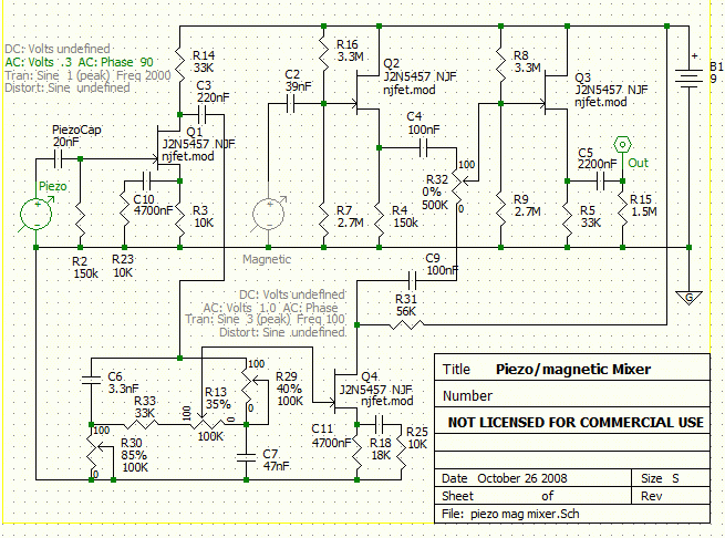 bwps bwps reports: "Q1 source 2.2v drain 2.2v
" Regardless of the current in Q1 the effective drain to source resistance must be zero. Let's look at how this might play out. The total voltage from B+ to ground is 9.3v (based on his report of the voltage on the drains of Q2 and Q3). The series resistance in this branch is R14 + Q1 + R3. 33k + 0 + 10k = 43k The current must be B+ / R 9.3v / 43k = 0.216 mA Voltage across R3 = Itotal x R3 0.216 mA x 10k = 2.16v That's way close enough to 2.2v given variances in actual component values and measurement accuracy. We don't know whether the FET is shorted internally or internally. But that's definitely the problem with Q1, wouldn't you say? |
|


