|
|
Post by ashcatlt on May 20, 2009 22:12:22 GMT -5
ashcatlt, are you saying the drawing in your last post would also work with the additional wire down to the safety cap? Yep. Can you see why? Depends on how much you worry about tiny ground loops with the tiny signal levels we're talking about here. I probably wouldn't bother, but I think best practice says to isolate them if possible. |
|
|
|
Post by sumgai on May 20, 2009 22:33:28 GMT -5
ange, Don't let me pee in your Cheerios, but we all need to get on the same page. Here's your lesson for the day, please write it down in your notebook, there'll be a test later in the period. ;D Your diagram in Post #20 was correct. Newey knew better than to give you any grief for it, but he was having a Miller Moment (it was after 5:00pm in his time zone, so he put his thinking cap on the shelf, and went down to the corner pub for a Millers), but the rest of us all saw the same thing - this diagram will work as you wish. So, here's what you take away from the whole thread..... Electrically, every point within a circuit between components will have the exact same value. Only a component such a switch or a resistor, etc. can alter that value. Hence, it doesn't make a bit of difference where you physically connect a wire (or a component), so long as all the wires and connections are made (preferably correctly!), and tested, before you close up shop. In terms of where to hook something up physically, the above "Rule Of Thumb" says that if your wire isn't long enough to stretch from Point A to Point B, as called for in the drawing, then you can hook it up to another point that, electrically speaking, is at the same potential. (IOW, it would have the same voltage reading, if the circuit were 'live'.) I trust I've made this clear, but if not, ask for clarification. We'll stick with it until you get it as soldily as the rest of us.  HTH sumgai |
|
|
|
Post by sumgai on May 20, 2009 22:43:03 GMT -5
guys,
Depends on how much you worry about tiny ground loops with the tiny signal levels we're talking about here. I probably wouldn't bother, but I think best practice says to isolate them if possible.No, there's more to it than tiny ground loops. As noted earlier in this thread, and often throughout this Forum's life, if you use the QtB method of constructing a Faraday cage, then it behooves you to isolate the pot shafts from the back-of-the-pickguard shielding. The reason being, those shafts are metal, and thus are good conductors. Now you might be using plastic knobs, but what happens if you decide to go for a set of metal jobbies?  Or worse yet, you do this mod (the QtB) for a friend, and he switches to metal knobs, without telling you in the first place? See where this is leading? Yes, the chances of getting fried are still small, but my take is, if you're gonna invest the time and effort to reduce the risk as low as possible, why stop at doing the job only 95% of the way? It's no additional money, and only a few moments of time to cut away the shielding that would contact the pot's washer and/or shaft, and when done, one can sleep more easily at night, knowing that all the bases were covered. ;D HTH sumgai |
|
|
|
Post by angelodp on May 20, 2009 22:48:42 GMT -5
Yes I get it.... there are many ways to skin this cat. And yes on the isolation of the pots to be closer to a clean build and eliminate that loop ( small as it may be ), I get it all. This process, albeit laborious for the conoscenti, has been very instructive and helpful. Now onto installing this.
best Ange
|
|
|
|
Post by angelodp on May 20, 2009 23:35:49 GMT -5
Ok, here is my test, I hope this flies as the non safety cap version.  |
|
|
|
Post by ashcatlt on May 20, 2009 23:45:00 GMT -5
Okay, what? The pots, along with all the other touchable stuff (except the jack itself), are isolated from dangerous DC voltages by the iso cap. So's the faraday cage. It was my understanding that QTB as per Mr Atchley involves removing the connection between the back of the pots and allowing - in fact requiring - the shield foil to carry that connection. It was ChrisK's idea (at least this time) to re-introduce that between-the-pots wiring so as to not rely on the shield as a conductor. I'd like to mention that in this particular wiring the farady cage will not be grounded at all if all the pots, switches, and the jack are isolated from it. There's that ring terminal around the T pot's shaft, but if the shaft is isolated from the faraday cage there's no conductivity to the amp ground, and therefore no shielding. Or did something go really weird while I was down with the plague? |
|
|
|
Post by angelodp on May 20, 2009 23:48:46 GMT -5
Oh sorry, this is a version without the Faraday box. Just adding a DPDT switch to the existing wiring.
A
|
|
|
|
Post by ashcatlt on May 20, 2009 23:49:08 GMT -5
ange, you ninja'd me.
In your new pic, the "series override" switch shorts out the bridge pickup, and acts as a "neck override".
|
|
|
|
Post by angelodp on May 20, 2009 23:57:41 GMT -5
Is that because the grey wire seemed to go the switch body instead of the terminal. I reposted the graphic with a fix for that.... photoshop error.
wait - man I am thick.... I switched the wires on the pups and reposted a fix above. Sorry, I am a bit dyslexic and I get things switched like that at times.
|
|
|
|
Post by ChrisK on May 21, 2009 10:52:34 GMT -5
So, did you hear about the dyslexic agnostic insomniac that stayed up all night wondering if there was a dog?
The drawing in post 34 will work fine. It is not a safety cap-based design.
The drawing referenced in post 28 will not work; the bridge return wire goes to the neck return in parallel (and both of them happily go nowhere together) and it goes nowhere in series where the bridge pickup should drive the neck.
The bridge return needs to be connected to signal return.
|
|
|
|
Post by angelodp on May 21, 2009 11:29:48 GMT -5
ChrisK you mean post 34 I presume not 31.
|
|
|
|
Post by ashcatlt on May 21, 2009 12:38:24 GMT -5
The drawing in post 28 will work if the ground is connected as indicated in that post. It then functions exactly as the drawing referenced in post 27.
|
|
|
|
Post by angelodp on May 21, 2009 15:33:12 GMT -5
Ok, so to conclude this thread... I hope... this will also work. All roads lead to rome...sort of. Slight correction on my side bar - All the components will be isolated for the faraday box as they pots, switch and jack are grounded by alternate methods. lol ange  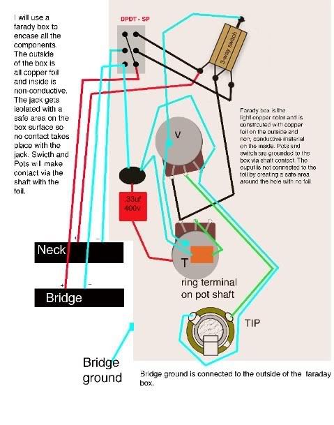 |
|
|
|
Post by sumgai on May 21, 2009 18:24:32 GMT -5
The pots, along with all the other touchable stuff (except the jack itself), are isolated from dangerous DC voltages by the iso cap. So's the faraday cage.
It was my understanding that QTB as per Mr Atchley involves removing the connection between the back of the pots and allowing - in fact requiring - the shield foil to carry that connection. It was ChrisK's idea (at least this time) to re-introduce that between-the-pots wiring so as to not rely on the shield as a conductor.
I'd like to mention that in this particular wiring the farady cage will not be grounded at all if all the pots, switches, and the jack are isolated from it. There's that ring terminal around the T pot's shaft, but if the shaft is isolated from the faraday cage there's no conductivity to the amp ground, and therefore no shielding.
Or did something go really weird while I was down with the plague? No, nothing went weird on you, at least not on my watch. In point of fact, Chris prefers to not rely on any shielding material to act as a conductor for any kind of current flow. In his purview (and mine), once a shielding material has "caught" a noise-type signal, the prudent designer doesn't rely on the shield to carry that signal to its final destination (the furthest most ground connection), he/she designs a separate circuit to carry that charge of electrons - this would be the buss wire from one pot shell to another, and thence to the capacitor, etc. Which points out that yes, in some manner one will need to ensure a physical and electrical connection between the shield and the capacitor. I myself would prefer to solder the cap's lead directly to the shielding material. But I tend to forget, some folks use aluminium instead of a real shielding material, and that means that a physically clamped connection will be mandatory. For that I must apologize for my rant, above. I hereby correct it in the following sentence: Correction: When using aluminum as the shielding material, soldering the cap's lead to it will not be possible. In such cases, a method of clamping a wire to the material will be necessary. Using a ring terminal under a pot's washer is one way to do this, but a screw into and through the material (and thus into the wood) is also acceptable. /correction I trust this will suffice.  sumgai |
|
|
|
Post by ChrisK on May 21, 2009 19:00:28 GMT -5
distraction
When using aluminum as a shielding material, soldering to it is possible. It is complicated and requires that the aluminum workpiece be covered by molten solder. The method is to scratch the surface of the aluminum, thereby cutting thru the oxidation, and allowing the solder to bind to the bare aluminum metal surface, kept free of rapid re-oxidation by said molten solder. A repeated process of scratching thru the oxidation within the pool of molten solder is required. A soldering iron tip with sharp edges is required, preferably an iron-plated tip is used. Once many such cuts are made, the excess solder is removed and the piece can cool. Since the area is now soldered, other metals can be soldered to the solder.
However it is difficult to keep a pool of solder molten, especially if it is on aluminum, which is an excellent conductor of heat (away). Furthermore, aluminum foil rapidly "goes to be with Jesus" when subjected to significant heat.
And that, boys and girls, is why we invented copper.
And why aluminum house wiring was dumb stupid to begin with.
/distraction
|
|
|
|
Post by ashcatlt on May 21, 2009 21:33:54 GMT -5
Slight correction on my side bar - All the components will be isolated for the faraday box as they pots, switch and jack are grounded by alternate methods. But then, by what alternate method will you be grounding the faraday cage? |
|
|
|
Post by angelodp on May 22, 2009 0:10:41 GMT -5
any suggestions.
|
|
|
|
Post by angelodp on May 22, 2009 12:47:35 GMT -5
|
|
|
|
Post by ashcatlt on May 22, 2009 13:10:22 GMT -5
My suggestion would be to leave at least one of the pots or the switch in contact with your copper foil. In fact, since it seems like extra work to isolate them, I'd probably just leave all of them connected.
|
|
|
|
Post by angelodp on May 22, 2009 13:42:39 GMT -5
Bear with me. Ok so I m going to see if I do get this. Now that I want to isolate the pots, switches, and jack I have had to rethink this. After checking my mini-DPDT switch I have confirmed that it is in fact self-isolating ( it that is a term ), an that the DPDT does not need to be grounded to the touchable node because the toggle is not electronically connected to the terminals. The Gibson switch does need to go to the untouchable node ( UTN ), as do the pots, and the faraday cage, so i have linked the pots and the Gibson switch and the faraday cage. The two nodes UTN and TN ( touchable node ) are insulated. Please note that this post has new language in the side bars and notes. I believe I have the two camps UTN and TN worked out. Comments please. 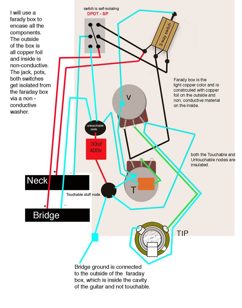 |
|
|
|
Post by D2o on May 22, 2009 14:03:57 GMT -5
Hi Ange,
I'm not exactly sure what you're asking, but you can use the soft plastic lid of a margarine tub (Becel, for example) to make lovely non-insulating washers (and they are also heart-healthy!) if you want to avoid having the pots come into contact with the shielding.
However, I am with Ash. I am not sure I see that as much of an issue, really - some techs are quite in favour of having what amounts to a redundant ground.
But I would definitely ensure that the jack does not come into contact with the shielding.
Does that help?
|
|
|
|
Post by angelodp on May 22, 2009 14:09:37 GMT -5
Ok so that is where I am getting confused. i thought that the jack ground was supposed to go to the touchable node since it is touchable?? Which brings me back to this layout, putting the jack at the UTN??? 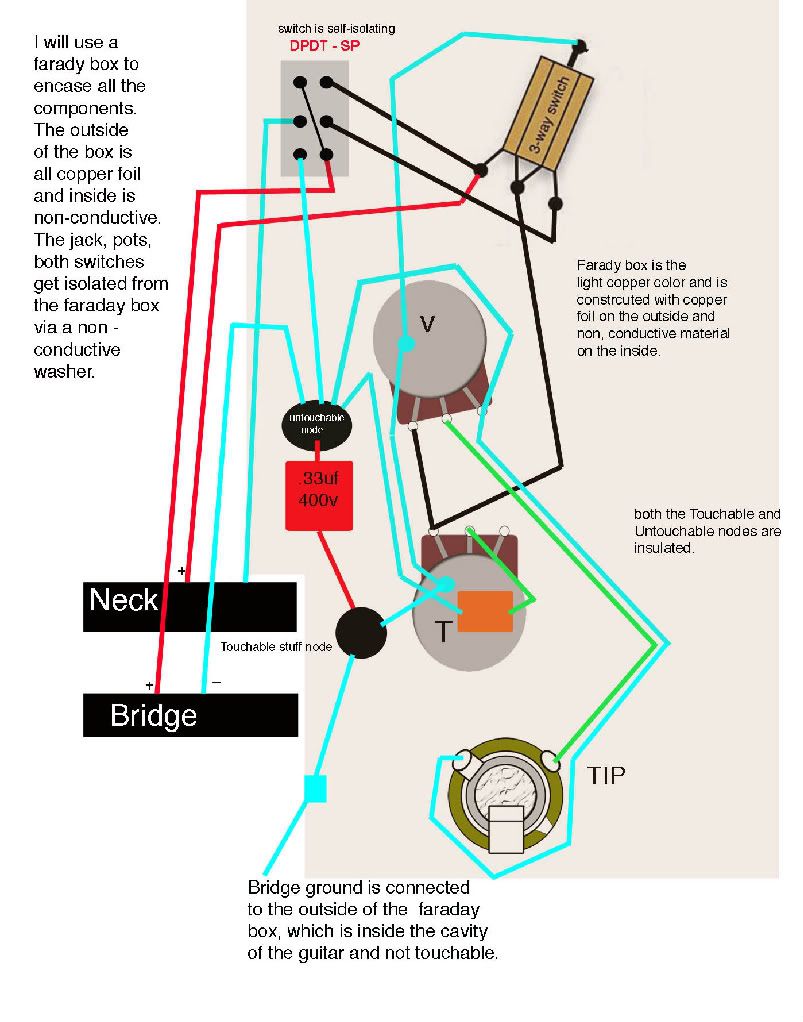 |
|
|
|
Post by ashcatlt on May 22, 2009 14:10:34 GMT -5
 The sleeve of the jack needs to connect to the untouchable side node. The chasis of the amp to which it is connected is the part that could possibly make anything not isolated by the cap dangerous to touch. The jack itself is touchable, of course. Unless you intend to replace it with an isolated (plastic) one, you'll have to attach a "Do Not Touch" sign, at least an imaginary one. Even an isolated jack doesn't help much if the cable you use has a touchable metal barrel. As it is now, you've got all the touchable stuff unisolated (bad!) and all the untouchable stuff isolated for no good reason. Anyway, from the simulations I've run, it looked like the hi-pass filter created by running everything through the iso cap on its way to the jack (what you've got in the above picture) rolls off low enough to not affect too much of the usable guitar range. So you might be able to move everything but the jack sleeve over to the untouchable node and be done with it. Edit - Since I was ninja'd, and to reinforce the point. The jack and cable barrel will be "hot" if the amp fails, and there ain't much you can do about that except remember it. If your amp starts smoking or making horrible noises, disconnect it from AC power before attempting to disconnect it from the guitar.
|
|
|
|
Post by D2o on May 22, 2009 14:14:31 GMT -5
Ok so that is where I am getting confused. i thought that the jack ground was supposed to go to the touchable node since it is touchable?? To clarify, I mean that I would ensure that the jack's post and nut (whatever they're called ... the bits that actually attach the actual jack to the guitar) do not contact the faraday cage - i.e. the only things in contact with the jack are wires ... wherever they may have come from. Am I clarifying or muddying?   |
|
|
|
Post by angelodp on May 22, 2009 14:20:10 GMT -5
OK assuming that the jack does not touch the farady box then where does the jack ground go to .... the Touchable or Untouchable node??
ange
|
|
|
|
Post by angelodp on May 22, 2009 14:27:49 GMT -5
This is what is confusing to me as the notion that all Touchable stuff excludes the jack itself. Should that not be noted.
ange
The Touchable Stuff Node
This is the externally touchable node. This is what is usually connected to this node: ANY conductive thing that might be touched by the operator or bystander (innocent or not).
The bridge ground wire. This AC grounds the fixed or vibrato bridge.
Any metal (conductive) knob/shaft/pot shell that exposes the operator (or drunk onlooker/toucher) to any conductor coming from the amp via the guitar cord.
If the pot back shells/shafts/metal knobs are touchable, the bent terminal connections from the signal returns must be removed and the pot signal return terminals connected to the signal return node, and the pot back shells connected to the touchable stuff node
Any metal (conductive) pickup cover.
Any frame ground terminal on a switch such as the LP toggle or 3/5-way lever.
ANY conductive thing that might be touched by the operator or bystander.
|
|
|
|
Post by D2o on May 22, 2009 14:29:33 GMT -5
Ange, I'm not really sure how to answer that ... I'd only be guessing because I'm not quite following the touchable / non-touchable nodes (I am sure that is my own shortcoming, not yours). By the way, is there any way you could cut that picture's size about in half? ... I'm getting seasick   |
|
|
|
Post by ashcatlt on May 22, 2009 16:54:54 GMT -5
I hear (read?) your confusion and frustration. To be honest, I'm a little frustrated with this thread myself. Seems like every time you get it right, with just a minor correction to make, you go and change something completely different and we have to start over from square one. That's how we learn though. I expect that by the time we get this right you will be an expert at these things, and ready to help others. I was pretty sure that ChrisK's "untouchable" post included a caveat re: the output jack, and here it (they) is (are): One node is the signal return path. This starts at the output jack sleeve and is connected to all internal signal return points. ... The output jack is usually not an isolated sleeve jack, so in the case of a Strat, the jack plate is connected to the sleeve/threaded barrel of the output jack, and hence signal return node and is inherently dangerous to touch. On a Tele, the output jack cup or mounting plate is similarly connected to the signal return node. ... The signal return nodeThis is the internal untouchable node. This is what is usually connected to this node. The output jack sleeve. ... The danger comes from the amp. Specifically, it comes from the potential for a very large DC Voltage to be applied to the amp chasis, and conducted to the guitar by way of the cable shield. Anything connected directly to the amp's chasis via the cable shield, without passing through a properly rated (for voltage capacity) cap will be dangerous to touch in the case of this unlikely type of failure. A number of folks around here avoid the issue altogether by connecting to the amp via wireless transmission. DC voltage can't jump that gap. Your reciever might fry, but you won't. I don't use old dangerous tube amps, which tends to accomplish the same thing. I'm really starting to think there's no good reason not to just wire up a special cable with the iso cap in series with the shield connection at the amp end. |
|
|
|
Post by D2o on May 22, 2009 18:35:38 GMT -5
Ash, A couple years ago we had a similar discussion in which we went all over the damn place - even to chatanooga ...Here's what the big gai had to say about jacks touching the shield: And here's what he had to say about an external cord with a DC blocking cap: I hope that helps somehow. I will now return to my regularly scheduled weekend. Cheers, D2o |
|
|
|
Post by angelodp on May 22, 2009 22:41:42 GMT -5
More confusion, is this saying that the isolation cap affects the tone ??
Now, while it seems obvious, the fact is, most of us tend to forget that the ground portion of a circuit is still a portion of the circuit - it carrys the signal too! The effect of a capacitor will occur no matter where in the circuit you position it, inluding that part of the circuit labeled as "ground". Mr. Murphy personally guarantees that the effect will not be to your liking.
|
|


 Or worse yet, you do this mod (the QtB) for a friend, and he switches to metal knobs, without telling you in the first place? See where this is leading?