santellan
Meter Reader 1st Class

Posts: 63
Likes: 0
|
Post by santellan on Jun 4, 2009 17:14:03 GMT -5
Greetings to all, I just created a board design for a stratocaster based on the QTB wiring scheme as shown per my attached schematic. I would like to be able to say that it meets the authorized QTB requirements but I would like to have permission first and validation that it does in fact protect the user. For reference I am showing the board wired to the 5 position switch in the Bridge/Neck blender scheme. Hopefully I don't offend anyone with this post, I just want to do right by this group. Thanks for your help, Santellan 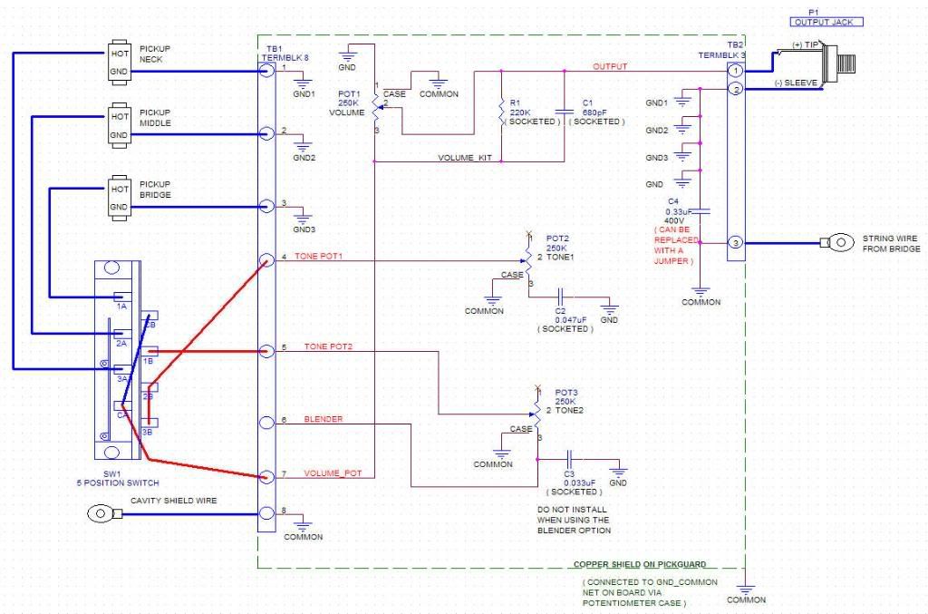 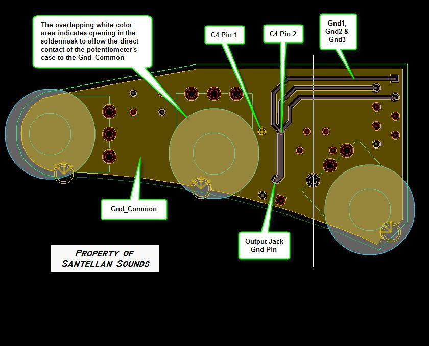 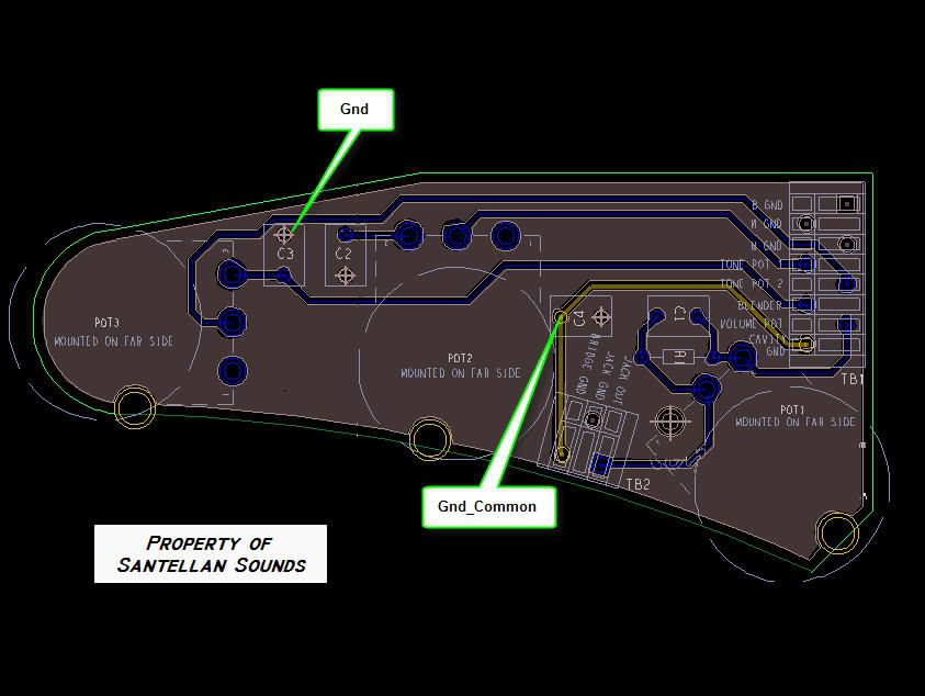 |
|
|
|
Post by newey on Jun 4, 2009 19:18:03 GMT -5
Santellan-
Good to hear from you again! I won't pretend to be able to vet your board for its efficacy in shock protection. However, a few points:
First, the term ""QTB" is an acronym for "Quieting the Beast". While shock protection is a feature of the scheme, the main point is hum reduction through shielding. Your design doesn't really have anything to do with shielding, but with safety- so the name is a bit of a misnomer.
Second, no one here can give you permission to use the phrase "QTB", as that phrase comes from John Atchley, the author of the original Guitar Nuts site (link appears at the top of this page). This board was "spun off" from the original site several years ago, and Mr. Atchley is, to my knowledge, not a member here. I don't know whether he claims any rights to the term "QTB" or not, but you'd have to clear any commercial use of the term with him.
Finally, the consensus attitude of this board over the use of the QTB "safety cap" design has been evolving over time. The recent discussions and posts of ChrisK on "shock hazards" shed a good deal of light, I think, on the question of the benefit, or lack thereof, of the safety cap.
Others have different opinions; suffice it to say that there is hardly uniformity on this topic.
|
|
|
|
Post by sumgai on Jun 4, 2009 20:46:15 GMT -5
Santellan,
What newey said above.......
Your circuit vets out correctly, although there is a spelling error: Do Not Used With Blender Option
Also, I'm not seeing the actual board layout itself, so I may be getting a bit ahead of the game - but you show everything else..... I'd suggest a jumper to complete the blender circuit, physically placed such that one can insert either a jumper or a capacitor for Tone 2, but one couldn't easily insert both at the same time. Probably easiest if you force the hole leading to Terminal 3 of the pot to share duties, because it can hold only one lead at a time. The user then chooses which of the two remaining holes to complete the desired circuit.
HTH
sumgai
|
|
|
|
Post by ChrisK on Jun 5, 2009 0:18:44 GMT -5
I'm not entirely certain what you want the lever switch to do,
but I'm fairly certain that it doesn't.
|
|
|
|
Post by sumgai on Jun 5, 2009 13:31:42 GMT -5
Chris is right (as usual), I missed it. On the selector switch, 3B won't do anything unless the switch is in the third position, and of course, that just defeats the ability to blend the bridge with the other two pickups. The board's Blender terminal should go directly to 3A. Tone 1 is wired to the common terminal of the B pole, which makes it a Master Tone control - which in turn renders Tone 2 moot. Tone pots 1 and 2 should be moved down one terminal on the B pole of the switch. And of course, an addition terminal on the board would let you offer a Master Tone option with the Blender, instead of what you have now. Shouldn't take much more to add that in, I think.  HTH sumgai |
|
|
|
Post by ChrisK on Jun 5, 2009 15:17:15 GMT -5
A. Well, only means that I'm not entirely certain what you actually had in mind for the lever switch et. al. B. Furthermore, only means that its current wiring doesn't do much of anything tone control-wise, any-way. (See "A".) It needs a good (re)GeThunkin' (or at least a good re-lookin' and re-drawin').  Now, drawing the correct wiring schematically is the easy part (once perfected). Since there are two circuit nodes (grounds) herein, separated by a 600 VDC 1 blocking cap, one must ensure that each follows class 1 spacing 2 requirements for separate class 1 circuits. In essence, for the sake of easy description, since the output signal and the output return are the same class 2 circuit 3, the operator touchable ground (GND_SAFE) must then be treated as a separate class 1 circuit. Typically this will entail PCB surface spacings (inter-trace) of 0.1 to 0.125" (consult U.L. standards for applicability in specific applications). This means every surface spacing between traces/pads/vias/warts and carbuncles must meet this. If the 600 VDC cap is rated for 600 VDC, then the PCB spacings must also be rated for 600 VDC. The solder mask is not considered to be an acceptable insulator since it is usually silk screened on, and is not specifically hi-pot tested on each production unit. It is meant to exclude solder adhesion and is not an insulator against surface creep voltage conduction. 1. A 400 VDC cap is permissible only if the maximum internally generated, externally presented through fault condition voltage is less than 400 VDC. If not, a 600 VDC unit is required and, if higher voltages are possible, a 1 KVDC cap should be used. 2. A class 1 circuit is one that is galvanically isolated from other circuits, and has a conveyed voltage over 42.2 VDC, or a conveyed current of 8 Amps or more, or a conveyed VA of 100 or more. 3. A class 2 circuit is one that is galvanically isolated from other circuits, and has a voltage under 42.2 VDC, and a conveyed current under 8 Amps, and a conveyed VA under 100. Exceeding any one of these parameters creates a class 1 circuit. If you are creating a commercial product with a feature or especially an implied safety improvement (the safety isolation blocking capacitor), you are giving the impression of merchantability and fitness of this feature, and hence you create the implied warranty of suitability for an application. To not design such to publicly available agency safety standards (such as U.L.) is often found in court to constitute design negligence. To not secure product listing under said available agency safety standards (such as U.L.) is often found in court to constitute negligence. Corporate officers and even design engineers have gone to prison in cases of sever injury or death resulting from products that were negligently designed. If this product is offered with a safety feature, and someone is injured or killed (or in the Peoples Republic of name_your_favorite_litigious_state merely p  d of) by an amplifier fault, you can bet that everyone in the saftey chain will be sued. And, there are folk a'board that, while eminently good-natured fun-loving music-wrenching rewiring-demented and generally okay-doaky, they are still lawyers (don't sell this to them). |
|
|
|
Post by ChrisK on Jun 5, 2009 16:14:45 GMT -5
tedfixxPosted based on santellan schematic edit on 20090605_1600 and the inclusion of PCB drawings. For a commercial product, DO NOT call the DC blocking capacitor a safety cap or even an isolation cap. It DOES NOT ensure safety, nor does it isolate the operator from all faults. Don't create the impression. 0.1" means 0.1". This means that ALL surface spacing between the GND_SAFE node and EVERY OTHER node must meet this spacing. Otherwise, while you may have a 600 VDC DC blocking cap, you do not have the PCB isolation between these nodes, and the applied voltage can arc over, or cause current flow through surface conduction (which can be assisted through the application of sweat and/or beer). A 0.33 uF 600 VDC cap is waaaaay bigger than you think.  600 VDC search.digikey.com/scripts/DkSearch/dksus.dll?Detail&name=338-1137-NDwww.cde.com/catalogs/940C.pdf400 VDC search.digikey.com/scripts/DkSearch/dksus.dll?Detail&name=BC1800-NDwww.vishay.com/docs/28111/28111.pdfwww.epcos.com/inf/20/20/db/fc_05/MKT_B32232.pdfThese are the ones that chesh procured and resold to the 'nuts a few years back. 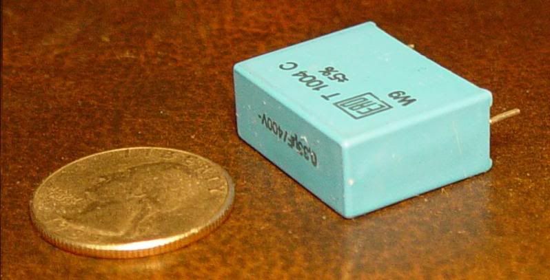 I use a safety isolation cap made by Nady (yep, I said safety isolation cap). It's their model XR-61, and is rated for 18 gazillion VDC, 1/10 of a bolt of lightning, or 250 feet (whatever). It has the capacitance for every note that I can play, up to the discharge point of its battery. While this was expensive (it was listed for $269.95), I got it for $50 during a GC sale. It works ok. For a similar $50 I bought the Korg hand-sized amp modeler a few years back. For most practice and all travel sessions (in that foreign country known as Ohio), it's just fine and sounds quite similar to my VOX "something or other 50" amp with (yep) the same digital front end in it. In this case, I only need a 6 VDC cap to protect me from that 3 VDC battery failure. 
|
|
santellan
Meter Reader 1st Class
Posts: 63
Likes: 0
|
Post by santellan on Jun 5, 2009 16:34:41 GMT -5
I updated the schematic and added the board views for reference.
The 5 position switch should have the standard pickup combos except when using the blender option. I will post a correct wiring drawing of this option later.
The schematic shows N/M pickups on Tone Pot1 and B on Tone Pot2 as an example. You can assign the Tone Pots as you please by inserting the proper wire or wires from the lever switch to the appropriate tone pot location on the terminal block.
In the standard option you can insert whichever value orange drop cap you want for each tone pot.
Same for the volume kit on the volume pot.
In the blender option tone pot 1 becomes a master tone and tone pot 2 acts as a switch for allowing you add the neck or bridge in position 1 or 5. The capacitor for tone pot 2 must be removed when using this option.
Now as for the 600V Hi Pot test I will have to reconsider whether I want to market the product with this feature. As we know not one guitar manufacturer meets this standard.
What I can do is design it for IPC standards for 600V, Type B4 ( external conductors, with permanent polymer coating for any elevation ) spacing requirements which comes out to 1.83MM.
Thanks so far for the input.
Santellan
|
|
|
|
Post by ChrisK on Jun 5, 2009 16:44:01 GMT -5
What I would do is lay the PCB out for 600 VDC spacing (well, for class 1), add provisions for the blocking cap as well as a jumpering option to defeat it (in place of it), and not mention anything about its purpose other than to say that some folk like to "install a cap between the signal/cable/amp ground and the exposed external metal components".
I wouldn't even say why they like to do so.
Or just talk about signal shielding.
|
|
santellan
Meter Reader 1st Class
Posts: 63
Likes: 0
|
Post by santellan on Jun 5, 2009 16:56:33 GMT -5
Chris,
Sounds good to me. I will update the schematic and board views to focus on the shielding features. I will also update the board to have the correct capacitor sizes and increased trace spacings as well.
Thanks,
Larry
|
|
|
|
Post by sumgai on Jun 6, 2009 0:03:53 GMT -5
.......
And, there are folk a'board that, while eminently good-natured fun-loving music-wrenching rewiring-demented and generally okay-doaky, they are still lawyers (don't sell this to them). We still got weasels lawyers in here? Geez, I thought we sprayed for them just last month! ;D Chris, kindly disregard my PM of 10 minutes ago.  Thanks. sumgai |
|
santellan
Meter Reader 1st Class
Posts: 63
Likes: 0
|
Post by santellan on Jun 6, 2009 9:58:37 GMT -5
Chris, Are guitar manufacturers required to meet UL standards? If not how do get pass this when selling to the general public? Just for reference here is the 600v spacing rule using the IPC design standards? It's a bit smaller than UL but it is meant to meet a 600v hi pot test. What do you think about IPC standards. Also wouldn't a fuse at the output jack be a simpler solution? 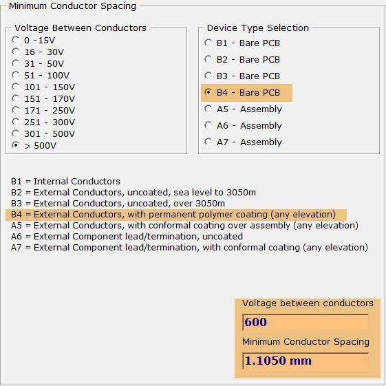 |
|
santellan
Meter Reader 1st Class
Posts: 63
Likes: 0
|
Post by santellan on Jun 6, 2009 10:37:29 GMT -5
Has anyone tried the .02uF 400v cap versus the .33uF 400v. Does it allow more noise at stated?
|
|
|
|
Post by ashcatlt on Jun 6, 2009 16:12:59 GMT -5
Also wouldn't a fuse at the output jack be a simpler solution? Unless it's been purposely defeated, there's already a fuse on the amp to protect against this particular fault. The "problem" is that this fuse isn't likely to blow before the guitarist does. The best solution, AFAIK, is what Chris said. From the models I've run, the .33uF cap has it's -3 db point somewhere around .5Hz. At least it does when put in series with the signal hot. 5spice shows it doing nothing at all when put in series with the signal return(ground). For the .02uF, it's somewhere close to 10Hz. This is not generally considered an audible frequency. This is also the reason I'm still confused as to why we don't put the cap at the amp end of the cable, in series with the shield, thus saving us from having to include the caveat re: the cable/jack. |
|
|
|
Post by JohnH on Jun 6, 2009 18:45:56 GMT -5
Yes, why are these un-safety caps so large? As Ash says, could we not use somethng smaller, maybe on both ground and signal wires for better isolation?
The reason may be related to wanting as good a shunting to ground as possible for the spurious hum and noise. I find that tricky to figure out and to model, but It might be interesting to try some tests to see how hum and noise increases as the direct route to ground is replaced by one via progressively smaller capacitances.
John
|
|
santellan
Meter Reader 1st Class
Posts: 63
Likes: 0
|
Post by santellan on Jun 6, 2009 21:20:19 GMT -5
|
|
|
|
Post by ChrisK on Jun 6, 2009 21:33:20 GMT -5
Yes, however it's unrelated to the issue. Yep, the operator will blow thus protecting the fuse. A fuse is unrelated as it protects in the event of excessive current (or internal heat rise usually caused by current). While a Hi-pot tester will test for adequate spacing and hence isolation, if you apply one directly across a fuse, it will just sit there and snicker. I had an issue with brush-cut shards causing commutator shorts on small DC motors once. These were lot-related and a manufacturer's problem. The production facility offered to burn these off with a hi-pot tester. Both the defective motors and I just snickered a lot. Potential is good, potential is fine, but current does all the work. Now, to the concept of isolating the operator at the amp end of the cable. ABSOLUTELY (pssst, use wireless, it's a bazillion volt cap). First, test every outlet, every time. My wife and kids ask my why I check the car doors after using an RF fob to lock them. I say, "how do you know when things have failed?" To their surprise, gee, I'm the one that finds the failed lock mechanisms. (Also, since I drive manual transmission cars, I would be negligent if I left one unlocked and a child released the brake and took it out of gear.) Second, use a GFCI cable, on every outlet, every time. The best place to stop the Huns is before they get to the gate. When did Noah build the ark? (Before it rained.) Third, let's think about these caps. On one hand we want to buffer the operator from the application of a high DC potential, but want to couple the noise to the amp chassis. A certain value of capacitance is needed since the lowest noise frequency of interest is 50/60 Hz. A 0.02 uF cap has a reactance of 159,155 Ohms at 50 Hz. That wouldn't be described as a solid connection. A 0.33 uF cap has a reactance of 9,646 Ohms at 50 Hz. On the other hand we want to prevent the coupling of AC fault current through the operator. This speaks to an absolute minimum value of capacitance, oh dang that 50/60 Hz is real close to "frequencies of interest tonally". Especially on a bass. And, we just can't isolate the ground/shield at the amp as there is still a conduction path through the guitar electronics. We have to isolate the signal as well. So that's two caps. Effectively in series. To realize 0.02 uF, we need a 0.04 uF 600 VDC for both connections at the amp. To realize 0.33 uF, we need a 0.66 uF 600 VDC for both connections at the amp. I don't even want to get started on "oh, then we only need 300 VDC caps" either. Ain't so, no way. Shut-up. We could design a device that limits the current through to the operator and the voltages applied to the operator, but that would require a known tested good point of reference, such as a properly grounded mains outlet. No matter what you do or think through, it all comes back to the intrinsic safety of the mains outlets with a safety ground, using equipment WITH a safety ground (sorry two-terminal unpolarized plug, capacitively coupled chassis to neutral/hot leads old fashioned tube amp aficionado's, using that stuff IS negligence), checking every outlet every time, and using known safety devices such as a GFCI cable AND GFCI outlets. We use them in the bathroom and kitchen to prevent our children and mates from shock and death, aren't we worth it as well? |
|
|
|
Post by sumgai on Jun 6, 2009 22:10:33 GMT -5
What Chris said! And to cap it off, pun highly intended, we don't bother doctoring up the amp as we do the guitar, because we can take the guitar from amp to amp as we roam the town looking for gigs. Who knows what amp might be waiting for us at the next venue? The amp might see many different guitars, true, but it's not likely that we're playing all of them, only our own. Unless you fancy fixing up all your mates' guitars.....  Capacitors need to be a certain physical size in order to operate, it's a matter of certain laws of physics and all that. The selected value of 0.33µf at 400 vDC is a compromise, to be sure. Some users will not protected at all, their body's internal resistance, including their skin contact resistance, is so low to begin with, they really are organic fuses.  Other users have so much internal resistance it's not funny. I once knew a guy, back in my Army days, that could literally drop any finger or his whole hand across two leads coming directly out of a wall socket - and this was in Germany (hint: greater potential)! If his skin was wet, then it was no dice, but on a normal working day, it was fun to watch him take an FNG's money on a bet.... ;D (Gotta admit, I paid up like a man.) HTH sumgai |
|
|
|
Post by ashcatlt on Jun 6, 2009 22:53:18 GMT -5
For sum reason, I'm now remembering how much I love outlets I can't actually see.
|
|
|
|
Post by ashcatlt on Jun 6, 2009 23:28:26 GMT -5
This may be  ... The AC leakage to which Chris occasionally alludes in these discussions is quite specifically not the point of the capacitor, which he correctly terms a DC blocking cap. Luckily for us  , AC leakage is far more common. This voltage is usually annoying, occasionally painful, and rarely enough to cause damage to equipment or operator. On the other hand if an old, poorly maintained tube amp fails in the particular way that the DC blocking cap is intended as "proof against" (even rarererer), the voltage will be enough to kill. It really doesn't matter what happens to the fuse after that. The fun part about AC leakage is that the frequency we want to attenuate to save ourselves from physical pain is the exact same frequency that causes us the most noise headache - that of the AC mains. Any shielding action only works for frequencies which are passed with relatively little resistance to the amp. Those which can't pass (thanks to the cap) will basically bypass the shielding altogether, and bug the heck out of us. |
|
|
|
Post by JohnH on Jun 7, 2009 0:37:45 GMT -5
Well, just out of curiosity, I inserted a 0.02 cap on the ground connection of a guitar cord. A big increase in hum ensued, so a bad idea. Audibly, maybe 1/3 of the noise of a fully disconnected ground. With a 0.33 cap, the noise was much less but still significant and unwanted.
So I don't see myself putting these ground caps in my guitars. I think that Chris and Sumgai are expounding the correct approach to safety of the system.
But suppose one wanted to consider this further, and assess ideas that may provide more electrical isolation, without adding noise. My first question would be, what would be a suitable circuit model for thinking about induced hum and noise? How would you draw a circuit that could be analysed ie, what is the mental model of the noise generator? (analogous to how the sound signal generator, the pickup, can be modeled as an ac voltage source with some L R and C components around it)
BTW, I see I am classed as a Quantum Mechanic today:
"quantum mechanics - the branch of quantum physics that accounts for matter at the atomic level; an extension of statistical mechanics based on quantum theory"
like...yeah...coooool!
John
|
|
|
|
Post by sumgai on Jun 7, 2009 2:03:01 GMT -5
QM (aka John), The DC blocking cap was never intended to be shielding friendly, it was meant only as a safety measure. If you'll fire up your SPICE proggie of choice, and feed in a steady stream of ever-increasing cap values, you'll find that in order to pass 50/60Hz with less than 1dB in reduction of level, you'll probably end up with the cap's value in the vicinity of 5µf. Note that in many older high-end hi-fi designs, and even some newer units, interstage coupling capacitors that need to pass the whole audio spectrum are easily 10µf, sometimes even more. (Probably in an effort to avoid phase issues.) sumgai |
|
santellan
Meter Reader 1st Class
Posts: 63
Likes: 0
|
Post by santellan on Jun 7, 2009 20:07:49 GMT -5
Thanks for everyone's input. I have decided to drop the blocking cap ( C4) and just focus on the single point ground shielding at the output jack.
I will update the schematic and board view later.
|
|


 Thanks.


 , AC leakage is far more common.