|
|
Post by newey on Sept 12, 2009 7:43:05 GMT -5
After mulling several options for the next project, I have more or less settled on a stereo wiring scheme. I've always wanted a stereo guitar. And I've rendered this in schematic form, a first for me. I had lots of help and encouragement from ChrisK and Sumgai with this, dipping my toes in the water of schematic design, so to speak. This will be a Tele style guitar. It has two outputs; inserting a single cable gives mono sound with various pickup selection options, while inserting a second cable into the stereo jack sends each pickup to a separate channel for stereo amplification. The diagram shows this with a 5-way switch, but in the implementation of this I foresee using a rotary switch. The Tele control plate will thus have 4 knobs in a row: 2 volumes, 1 tone control using a dual-gang pot, and the rotary switch. My dilemma is at Pos. 5 (yeah, I know, my numbering is reversed for a standard Strat switch, but again, it's actually going to be a rotary anyway). Logically, this position should be the bridge pup alone, but I can't seem to figure that out, I seem to have wired myself into a corner, so to speak. Pos 4, with the Br. pup through a cap, is also open for debate- I just kind of threw that in there for another sound option, but I'm open to other suggestions. 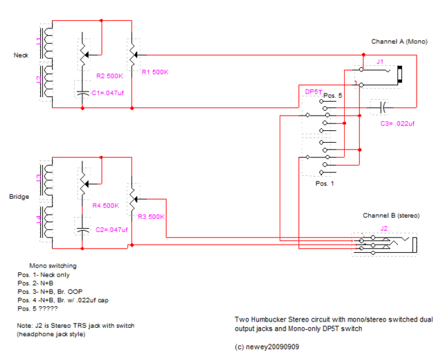 Gentlemen, you may commence firing at will . . .  |
|
|
|
Post by sumgai on Sept 12, 2009 14:22:13 GMT -5
At will, you say? OKaaaayyyyy...... Or if you'd rather be shot at from a roving time warp.....I say again, flip the 5-way switch around so that the Common terminals are connected to the Mono jack, and the various individual terminals become connected to whichever pickup leads you wish, per position. Leave the switching jack alone, it's in exactly the correct place to do the job. (You should more fully describe how that switching jack operates.) HTH sumgai |
|
|
|
Post by JohnH on Sept 12, 2009 16:16:53 GMT -5
Good stuff newey - thanks for putting up a schematic, its so much easier to get inside a circuit with that kind of thinking.
What did Will do that was so bad that we have to shoot him?
Now heres my thoughts:
What are your pickups? if single coils then do you want a series option? If humbuckers, do you want a coil cut option? Looks like you have drawn it as humbuckers, and if you want single coil sounds, your tone controls can do that at 10 if you want, which is how I wire my LP - so no added controls. You can also preserve humcancelling in OOP mode if wanted - more on that if its of interest.
To make the OOp option work, and also be able to switch both the neck and the bridge in and out, I suspect that a third switch pole is needed. If you use two poles on the neck to switch its ground and hot and one on the bridge hot (bridge ground hardwired to ground), then the OOP is acomplished by phase reverse of the neck. What that means, potentially very interesting in stereo mode, is that your OOp setting will also reverse the phase of the pups in stereo. You should get much less total cancellation of sound as compared to OOP mono, and instead a spacey phase expansion of your overall sound stage. I think that feature would be a really cool addition on a stereo axe.
If thats a good idea, and you agree about three poles needed, and if you dont want pickups in series, then you could have just four positions, being N, B+N, B-N and N. Thats a 3P4T switch which is still just a standard single layer rotary.
John
|
|
|
|
Post by newey on Sept 12, 2009 20:16:21 GMT -5
He ran this up the flagpole . . .  Many good ideas in there, so some contemplation and then, quite literally, it's back to the drawing board. Thanks, guys! The contacts are normally closed with no plug inserted, thus connecting to the switch for mono operation. Inserting a mono TS plug breaks the tip and ring contacts, allowing output from the bridge pup on channel B. Thanks to SG for the idea, which was actually contained in JohnH's speaker wiring PM to me from March, but I hadn't recalled it. Both will be 4-conductor + shield HBs. I have a GFS Tele Custom pickup (with the 3X3 polepieces) for the neck. I haven't secured a bridge pup yet, but it's going to be one of the GFS Filtertron style ones. Doing the coil cut with the tone controls is problematic since I planned on using a dual-gang pot for the tone. I'd be cutting both, or neither. I want the 2 volumes for the stereo setup so I can balance out the 2 pickups. With the rotary, that's 4. I'm not sure separate tone controls would work space-wise, that would mean 5 knobs across a Tele control plate. Even if they fit, they'd be too close together. I had not considered that stereo OOP might be worthwhile. I like that suggestion. And inter-pup series might also be worthwhile. I don't really want inter-coil series/parallel. If I have to go to a 3P rotary switch, my temptation would be to stick to 5 throws and add N*B. |
|
|
|
Post by ChrisK on Sept 12, 2009 21:24:53 GMT -5
Huh? Oooooh, you mean the twin humbucker (designed by Seth Lover after Fender poached him from Gibson, but he made them Fender bright - half-coils on the shell anyone), 2 volume 2 tone 3-way switch alder body Strat neck "gee we wish that we could compete with the Gibson SG" only Tele-looking Tele.   ;D Well, the spacey phase expansion/cancellation will occur in the brains of the audience, to varying degrees, depending on where they are seated. I do hope that you are playing in a steel safety cage. After all, not all listeners are capable of processing stereo audio signals, especially when "oh, that's just not right."  Back in the '60s, when I was in the military, I connected an 8 Ohm speaker in series with a 50 Ohm rheostat and mounted both within a cubic yard triple corrugated cardboard box (wood was tough to hew during the Alaskan winters). I did this as I'd heard that certain Beatle songs had common, but out of phase tracks for certain instruments. It really did create almost a third channel (the stereo separation sucked, the third speaker was bridging the power amps), but it was quite entertaining to the masses that had only heard stereo before. It was a really big hit with the missile launch crews (their only hope for excitement in life was bad in oh so many ways) and kept them occupied until the seizures started. But, with nukyaler warheads, close enough is usually close enough anyways. Slightly later in time, Lafayette Electronics decided that quadreo was the way to goeo. They were so certain that they invested all of their seed corn in it and fairly promptly went bankrupt. Apparently 2 1/2 was ok, but 4 was a crowd. I did learn several business lessons from this, primarily to get to the store very early as the best clearance items went fast, until they were all gone. I noticed some years ago that B. B. King's Epi signature model is a stereo output guitar. While this has enthralled his listeners for many years, do take note that he hasn't been able to sing and play at the same time since. Caveat Operemptor. |
|
|
|
Post by JohnH on Sept 12, 2009 21:31:15 GMT -5
newey - OK on the coil cuts, if its dual gang, both would be cut at once. would still work though. THis is the wiring of my LP guitarnuts2.proboards.com/index.cgi?board=schem&action=display&thread=3167But alternatively, would you buy the idea of your two volumes having push/pulls for coil cuts? Easy idea! Or do you just really prefer the Hb sounds? If you go to a three pole, and still keep 5 positions, you need a two layer switch. I got some good ones from Mouser, and they are reliable units. Ive got one still here, and assuming it was fitted to a face plate or pickguard, its total depth into the body is 30mm, to the tips of the solder lugs, so a 35mm rout would be just enough. Thats probably do-able on a Tele isnt it? If you build in a series option, your challenge is to configure it so that when in that position and the extra jack is inserted to split off the bridge pup, the result on the main output is not a nasty noisy open circuit, but instead defaults to just the neck pup. Your switched jack could do that job I believe. John |
|
|
|
Post by newey on Sept 12, 2009 22:14:29 GMT -5
So, I'm looking at a 2-layer switch, plus another switched jack on the mono side? A bit much, perhaps.
As currently wired, the switch is taken entirely out of the circuit by inserting a plug into channel B, so the problem is avoided, but I can see where the series would raise that problem.
So maybe the 3P4T is the way to go.
|
|
|
|
Post by JohnH on Sept 12, 2009 22:31:32 GMT -5
It would be just the one switched jack, as you have it. You only actually need to switch the hot connection of the bridge out of circuit whe then 2nd channel cord is plugged in. So if the switched jack has two poles, the second pole could, when the plug is pushed in, ground the series link that is made between pups for the series setting. It would need to be a real DPDT configuration on the jack, not just a 'break contact' type that is all that is otherwise needed with your system.
Personally, I think the series option goes well when you also have single coil options to go with it, since two Hbs in series is a bit too much wallop IMO. If theres no coil cuts however, then the 4 position parallel-only option is highly sensible and easy to use, and with that care over the OOp switching, responds very well to the use of stereo.
John
John
|
|
|
|
Post by newey on Sept 13, 2009 14:37:25 GMT -5
Here's the revised version. I am not at all sure that this is right. I haven't gone under yet, but I'm definitely treading water in the deep end of the schematics pool.  I have attempted to implement several things: 1) I took JohnH's advice, went with the 3P4T switch, depicted as a rotary. I also phased the neck instead of the bridge. I took his advice to just switch out the hot line from the Br HB. 2) I renumbered the switch positions to avoid any confusion. 3) I took Sumgai's hint to wire the commons to the mono out for the pup switching. I'm still mulling over the coil cut idea. For now, I'm sticking with this. I now have an unused switch connection on the stereo jack. I am also not entirely clear on the grounding here. Does (or should) Channel A share a ground with channel B (apart from through the amp)? What about frame grounds, do they need to be separate? I understand 2 stereo channels can share a ground, but should they in this scheme? And, more importantly, does this work? 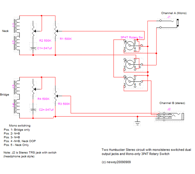 |
|
|
|
Post by JohnH on Sept 13, 2009 16:00:43 GMT -5
quick comments before going to work (its Monday again here - how did that happen?)
Your first schematic way of showing a switch with the lugs in an arc is more conventional, so easier for us to see, though your second way is clear enough.
With three poles, you can do it either with poles on the output side (as second diagram) or towards the pups, as first diagram.
Currently, theres no ground to channel B
Id suggest the poles as follows:
1 - to select which or neither of neck hot or cold goes to output
2 - to select which or neither of neck hot or cold goes to ground
3 - to select when bridge hot goes to output
bridge cold and both jack barrels go to ground
cheers
John
|
|
|
|
Post by newey on Sept 13, 2009 19:31:10 GMT -5
Thanks, JohnH! So, after a bit of cleanup and showing the grounds, is this now OK? 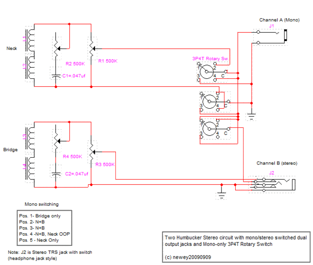 I couldn't find a symbol for the appropriate switch, so I had to custom-make one. I can always redo it if you think it's too awkward. |
|
|
|
Post by ashcatlt on Sept 13, 2009 20:14:14 GMT -5
I personally would avoid sharing the ground in stereo mode. If you're connecting to two seperate amps you'll be creating a pretty big ground loop. As with most ground loop situations, the actual impact here will depend on all kinds of factors external to the guitar itself.
I'm confident that the Ring terminal on your stereo jack will make a plenty happy ground connection on the barrel of the mono plug. If that's the case, you can use the other switch terminal on that jack to ground the bridge pickup to the mono jack. I'd hate to see a perfectly good switch go to waste.
|
|
|
|
Post by JohnH on Sept 13, 2009 22:55:54 GMT -5
I think Ash makes a good point, which I had not considered. I wonder if other stereo guitars address this ground loop issue?
On the diagram, it looks like pos 3 shunts the main jack, shorting output to ground.
I had a thought, having suggested this stereo OOP setting as possibly having worthwhile coolness, it might be worth rigging up a test to check how itsounds. I could do that out of interest, hot-wiring an extra lead into the back of my LP, and so taking two seperate channels. They could be recorded into Audacity, then one signal flipped by the software to see how it sounds. Would that be worthwhile?
cheers
John
|
|
|
|
Post by newey on Sept 13, 2009 23:17:33 GMT -5
JohnH-
Thanks for spotting the error, will fix!
A trial with the LP might be interesting, if you're game to try it and have the time. I suspect differing amps and speaker positioning has a lot to do with how this sounds, so a direct comparison may be tough. Also will depend on how close the digital "flip" in Audacity comes to actual coil cancellations.
But we might learn something, too.
And Ash-
Yeah, I've been questioning how the grounding should go. Your idea makes sense, so I'll use that as well- thanks!
|
|
|
|
Post by sumgai on Sept 14, 2009 2:41:32 GMT -5
newey, I'll agree with ash and John, use a separate ground for Channel B. Even if you experience no problems (with ground loops and such) during your first experiments, you'll eventually come across a situation where the only solution to the humming is to not go stereo - that's when you realize that the guitar shouldn't have shared the ground between the two output jacks.  Commentary: Commentary:I'd like to give discourse on "phasing". John, newey's correct to suspect whether or not Audacity can properly invert a channel's signal, and provide a realistic portrayal of what one would hear in the real world. But this isn't Audacity's problem, it's endemic to every piece of software. Why? Because they can't predict room acoustics. When we (S|P)OoP our pickups within the guitar, we're reinforcing certain harmonics and damping others - obviously a different set of harmonics than what we'd hear if we didn't throw one pup out of phase. This is noticible at all points within an acoustic environment, because the sound eminates from a single source (or multiple sources, but it's still mono). However, when we provide a true stereo signal to a plurality of sources (speakers), we create the so-called "sweet spot", where everything sounds as if were the original sound. But when we stand away from the sweet spot, we notice points where certain nodes (the acoustic equivalent of string harmonics) are reinforced or diminished. This phenomenon occurs with different nodes at different locations throughout the entire acoustic environment, with the obvious exception of the sweet spot. Now, juxtapose your pickup out-of-phase from one channel over these phenomena.... The only thing that really changes is the location for any given set of reinforcements/diminishments. Since the overall frequency output of each pickup is still the same, it stands to reason that when the speaker cone was going in, it's now coming out for that particular instantiation. This has the acoustical effect of moving the location of the various nodes, compared to the non-inverted signal, that's all. Only within the aforementioned sweet spot will a listener discern that perhaps the tonality has changed, but he/she probably won't be able to describe such difference in terms resembling the obvious change of one pup being in- or out-of-phase with the other. In short, for a software program to attempt to anticipate all this would require some mighty advanced algorithms, let alone some extremely high horsepower under the hood. It could be done, I'm sure, but at what final cost to the user?   For stereo, one pickup per channel, I don't think it's realistic to expect much difference in the overall tonality between in- or out-of-phase. </commentary> sumgai |
|
|
|
Post by JohnH on Sept 14, 2009 7:25:31 GMT -5
Well.... Heres what I think it may sound like. In this clip, first there’s a strum, switching from N+B in pure mono, to N and B going to separate channels – achieved using the guitar toggle. Then a rhythm, starting with pure mono with both pups, then stereo in phase (changes at 15s), then stereo out of phase from about 23s to the end. It does get more spacey sounding. www.soundclick.com/bands/default.cfm?bandID=674084&content=songinfo&songID=8096244For reference, here is the same track with the same changes, but all forced to be mono. The differences are mostly gone, except the last change which is now OOp mono, with the familiar honky OOP sound. www.soundclick.com/bands/default.cfm?bandID=674084&content=songinfo&songID=8096245The guitar is my LP with humbuckers, just a direct recording through a mixer – so think of the left and right speakers as representing two clean amps. I think the software inversion is equivalent to the same with switches on the guitar - they are both a 180 degree flip. But I think that there is alot more to explore with stereo rigs beyond this, using two amps that sound differently Anbyway I think this test was interesting to try. cheers John |
|
|
|
Post by ashcatlt on Sept 14, 2009 15:03:30 GMT -5
Haven't had a chance to listen to JohnH's little experiment there, but I think it is valid. As long as you play it back through a true stereo system, each pickup will be coming out of a seperate speaker in a different physical space. This should accomplish the whole thing with the acoustics about which sumgai is dissertating. I have to say that I tend to agree with sumgai on this, but I'll hold my predictions until I listen, then possibly try to offer my take on my observations.
I would like to mention that different signal chains will likely induce different frequency dependent phase shifts and possibly "absolute" polarity inversion, which just complicates things even more.
newey - you asked about the "frame grounds". I think that all shield type grounds (including the string/bridge connection, pot backs, and of course your cavity shield) should all go the sleeve of the mono jack. Unless, of course, your bridge pickup was one of those single conductor plus shield jobbies. Then it would seem you'd only have one option for that connection...
...but, I'm pretty sure you could get away with sending all grounds to the sleeve of the mono jack, and leave the sleeve (and ring) of the stereo jack altogether disconnected. Seems kind of strange, but I'm pretty sure that the signal return for the bridge pickup would find its way around via the chassis grounds ("virtual" or otherwise) of the amps, which must meet each other at some point. I'm not sure I'd want to trust that myself, though.
|
|
|
|
Post by JohnH on Sept 14, 2009 15:35:25 GMT -5
...but, I'm pretty sure you could get away with sending all grounds to the sleeve of the mono jack, and leave the sleeve (and ring) of the stereo jack altogether disconnected. Seems kind of strange, but I'm pretty sure that the signal return for the bridge pickup would find its way around via the chassis grounds ("virtual" or otherwise) of the amps, which must meet each other at some point. I'm not sure I'd want to trust that myself, though. I had thought the same, and when I first connected an aligator clip onto the neck hot connection of my LP to get the second channel, I didnt join another ground connection to the cord. It was a very weak signal going into the mixer (via some pedals acting as buffers), until I grounded the outer connection too. I think the reason was that the mixer input ground is not a chassis ground, so the grounds from other inputs do not meet. This is probably not an issue with guitar amps though, but being able to connect to a PA is a useful feature. |
|
|
|
Post by sumgai on Sept 14, 2009 18:48:34 GMT -5
ash, You've apparently forgotten the real name for "ground": signal return. If you depend on the signal return path of Channel A to provide the signal path completion route for Channel B, then why'd we have this discussion in the first place? The idea was to completely separate the two signal paths, so as to lower our chances of introducing ground loops, and any attendent noise thereby. No, I'm afraid that newey has chosen the correct jack - it should switch both hot and ground leads so that when both channels are engaged, the two pups are absodamnlutely isolated from each other, thus maintaining signal isolation for each entire signal path. Obviously when the plug is not inserted into Channel B's jack, then the ground lead should be switch to the sleeve of Channel A's jack. At that point, all series and/or phase switching will take place with the pickup nominally assigned to Channel A. I hate to say it, but the ideal solution that newey first envisioned still has not been rendered here. Do I need to lie to the other half and tell her I'm out gigging, when in fact I'm really down at the corner wi-fi hotspot, installing AutoCAD just so's I can do up a drawing?   sumgai |
|
|
|
Post by newey on Sept 14, 2009 21:44:53 GMT -5
SG- No, save your possible excuses for more fruitful endeavors.  I set out to figger this out my ownself- and I will, with some help and encouragement. Which I'm getting in spades . . .  John- Your demonstration was good to show what I'm looking at here, enough to convince me to proceed, anyway. Although, this project so far lacks a body and a neck, so realization may be away in the future. What SG said about the grounding confirms what I had been wondering about- but Ash seems to have a different view, so I figure I'll wire it up with the "floating" ground on Channel B, and if it's a problem, it should be apparent right away. EDIT:And I found one of these, so we're good to go!  |
|
|
|
Post by newey on Sept 14, 2009 23:03:26 GMT -5
Okay, I went back and corrected Pos 3 per JohnH's suggestion- and promptly realized I had more problems than just that. So, this is about version 7.0, but I think this should be right . . hopefully. I also (I think) dealt with the grounding issue, but again, please take a look. 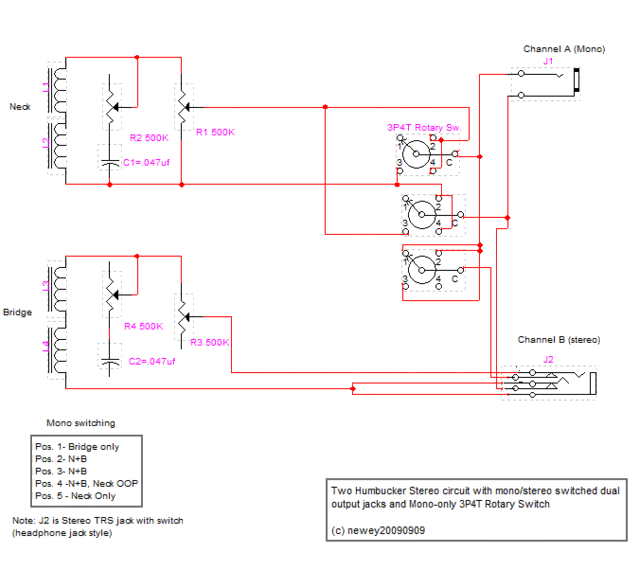 |
|
|
|
Post by JohnH on Sept 14, 2009 23:13:01 GMT -5
Final thoughts from me, until I think of something else:
Having the ground and hot for Channel B both switched out and independent when a plug is inserted is definitely the way to go, so when Channel B receives a mono jack plug, the barrel connects to the ring connection of the socket, then through the bridge pup coil, back to the tip connection and down the cord to the second amp. In that case there is no electrical contact at all between channels. The Channel B barrel connection (ie, the usual ground connection) is not used and is not connected to anything, so either it is a plastic socket or if a metal one, not mounted on the same metal plate as the main jack socket. Hence each channel gets proper connections and no ground loops can be created. All non-signal grounds, including all pot cases, bridge, non-signal braids, pup cases etc, go to the Channel A main ground.
Cool.
As for the Stereo OOP, it’s a freebie since it is made for the mono mode but doesn’t need any new parts to make it happen in stereo. As to the sound of it, how different it is to in phase may depend on how close together the speakers are. Not too close that you lose the stereo, but not too far apart that they can’t interact. I’d expect that the frequency below which there is an overall phase cancellation over a consistent field would be related to the wavelength and the spacing of the two speakers. With the common scenario of stereo wiring of two sides of the same cab, they are quite close, so you’d probably get cancellation and interaction quite significantly.
Anyway newey, I think it is a good project, that we haven’t previously explored on GN2, so keep at it!
John
ps on latest diagram, need to disconnect Channel B barrel, and swap the connections and contacts for the two other jack connections - the tip should go to hot which is the one on the left. Also, some missing connections on the bridge tone / vol controls?
|
|
|
|
Post by ashcatlt on Sept 15, 2009 1:10:32 GMT -5
The Channel B barrel connection (ie, the usual ground connection) is not used and is not connected to anything, so either it is a plastic socket or if a metal one, not mounted on the same metal plate as the main jack socket. +1 Especially since the jack-plate pictured above looks awfully conductive to me. It's pretty common advice - when trying to cure ground loop issues in pro audio - to lift the cable shield/ground connection on one or more of the sources. I consider it a last ditch attempt type thing, and never had to resort to this "solution", but I've been told that it works as well for unbalanced signals as for those balanced. Aw well, JohnH actually has tried it recently, and it didn't work. I did mention that I wouldn't probably do it this way myself. |
|
|
|
Post by sumgai on Sept 15, 2009 2:21:35 GMT -5
newey, You're missing a bet here! Since you're still showing the truth table as having 5 positions, I'll assume that you're not married to a 4Throw rotary switch..... As shown, simply "enlarge" the rotary numbering scheme by one. Position 1 remains as Bridge only. Next, for position 2, do NOT connect the bottom pole's terminal to the signal return on the Channel A output. Instead, connect it to the Neck's lower lead (the nominal negative lead). At the same time, disconnect this lead from the terminal at position 2 of the middle pole... WHALA! You now have N*B, in phase of course. Agreed about the sleeve versus ring ground connection on Channel B's jack - leave the sleeve floating freely, that'll let you use a metal jack mounting plate with no issues.  HTH sumgai |
|
|
|
Post by newey on Sept 15, 2009 5:47:38 GMT -5
OK, I see I failed to extend the connections from the pots to the bridge "cold" buss. That's what I get for late-night redrawing . . .
And yes, I forgot to eliminate the extra position in the table. While I'm not wedded to the 4T switch, it may come down to switch availability- and the number of decks, as JohnH suggests.
Perhaps I'll draft 2 versions, 4T and 5T. The 5T version could also then be implemented with a Superswitch if someone desired.
|
|
|
|
Post by ashcatlt on Sept 15, 2009 11:24:32 GMT -5
Agreed about the sleeve versus ring ground connection on Channel B's jack - leave the sleeve floating freely, that'll let you use a metal jack mounting plate with no issues.  The sleeve of both jacks will be connected by way of the metal jack plate. This will connect the amp chassis no matter what you do with that signal return wire. On top of that, the ring connection on the stereo jack will contact the barell of the plug nserted, which will also contact the sleeve. This jack must be isolated from the jack plate. |
|
|
|
Post by sumgai on Sept 15, 2009 14:01:08 GMT -5
ash, Nominally, the Switchcraft 14B is intended to be mounted with insulating/isolating washers. But you're correct, sometimes those washers get omitted....  Best to use a plastic mounting plate, and be done with it. Or two entirely separate mounting plates.... Ah, newey, just do whatever looks good in the final production run.  sumgai |
|
|
|
Post by newey on Sept 15, 2009 17:24:16 GMT -5
Yeah, I just posted the dual plate because I was surprised that anyone made such a thing. The curvature of the body in the area of the existing jack rout may well dictate the use of separate plates in any event, I'll have to see once I get a body for this build. For now, I have just indicated the need for isolation on the drawing. And, I fixed the switch table, and fixed the other problems. So, unless someone has some further input or other ideas, I'm thinking this is a final version: 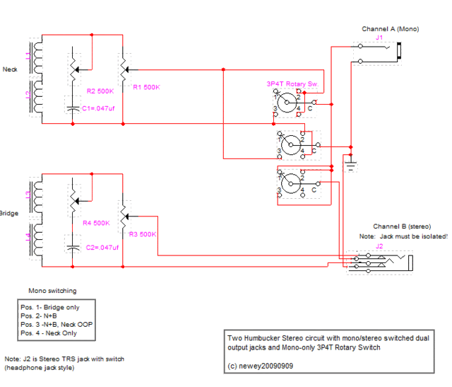 Although I may work up the 5-way version per SG's suggestion, just for consideration. |
|
|
|
Post by newey on Mar 4, 2010 22:56:44 GMT -5
Just bumping this thread as I'm working on the project and need to consult the schematic. Had to go 3 pages deep to find the thread, so a move is in order.
Still pending final decisions on the mono switching, to be dictated by the type of rotary switch with which I end up. Right now, I'm just drilling and mounting the 2 out jacks, and soldering the leads for the jacks first, so I don't have to demount the jacks later to wire them.
I have 2 separate jack plates, set about ½" apart, so as to avoid continuity between the channel grounds- but as it turns out, I needn't have worried, the switching jack I'm using for Channel B has a black plastic barrel which wouldn't make contact anyway.
|
|
|
|
Post by newey on Mar 5, 2010 22:36:10 GMT -5
OK, so I redid the schematic to show it "as is" currently, with a Dream 90 at the bridge instead of a HB. However, I forgot to change the title! 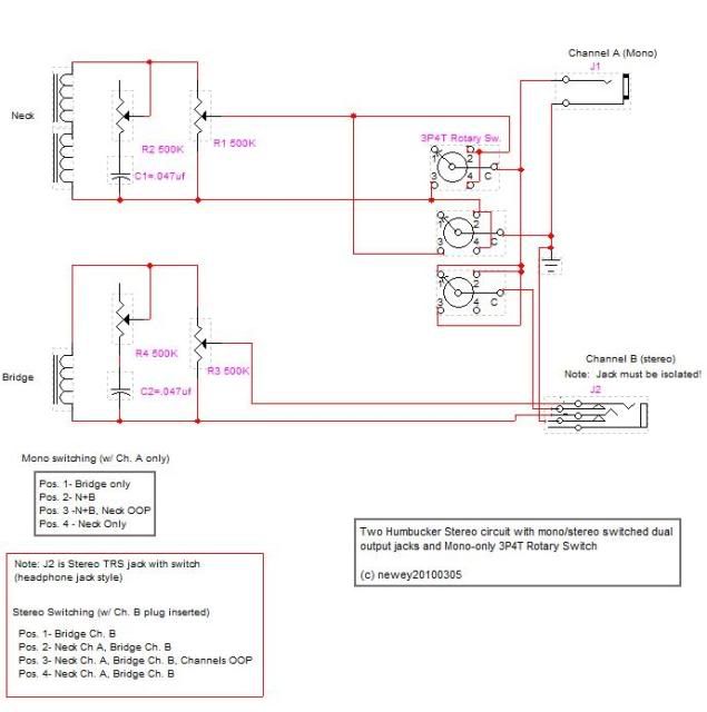 I also added a "truth table" for the stereo mode. This discloses that, with both plugs inserted and the switch set to Pos 1 (Bridge only), I'll get the bridge pup through channel B only, channel A will be dead. Is there a way around this? Can I get the bridge pup through both channels at that position? (I think this should be doable, but I haven't figured it out yet- I can't just jumper over to the switch, or it won't be stereo.) I have a 3P4T rotary on its way, so I won't be doing SG's suggested 5-way version. I just hope the switch fits, it's going to be close from the looks of things. I am, however, quite open to further suggestions. The more I consider it, I'm not sure I want to do the OOP option- although the P90 might be more interesting OOP with the HB than 2 HBs would be. |
|