|
|
Post by gangstarick69 on Oct 12, 2009 15:48:18 GMT -5
ive been having trouble with a jimmy page wiring kit i bought which wasnt working properly when it was meant to be in series mode and i noticed the diagram i used was slightly different to one that i found on the seymour duncan website, i was wondering will there be much difference if i try it the seymour duncan way? anyway heres the two diagrams please help me asap this is the diagram that came with the kit www.axetec.co.uk/2%20humbuck...my%20p age.gif this is the seymour duncan one www.seymourduncan.com/suppor...ematic=jp_style |
|
|
|
Post by wolf on Oct 12, 2009 17:47:10 GMT -5
|
|
|
|
Post by newey on Oct 12, 2009 21:34:54 GMT -5
G-ster-
What, exactly wasn't properly working? Were you getting no output in series mode? Were you getting one pickup only?
There are several different ways to wire series/parallel using a DPDT switch (i.e., a push/pull pot). All are equivalent.
I haven't done a detailed look at the 2 diagrams, but at first blush they both look OK. The variation between the 2 diagrams is not likely to be the cause of the problem.
More likely is a bad solder joint in there. Also possible is a bad switch. Bad diagram would be way down the list.
|
|
|
|
Post by gangstarick69 on Oct 13, 2009 4:24:50 GMT -5
sorry about that wolf i just copy and pasted the links because the hyperlink button wasnt working, anyway the first diagram i used everything was working fine but when i pulled the tone knob out to go into series i was getting very little sound out of the bridge pickup and by very little sound i mean i had had to have my amp turned right up, tried the seymour duncan one last night which is completely different to that one that wolf posted, the one which wolf posted looks alot better, with the SD diagram i used last night the bridge pickup didnt work at all, im pretty sure its not the pickups because they are practically brand new, any ideas anyone?
|
|
|
|
Post by sumgai on Oct 13, 2009 13:02:40 GMT -5
gr, Hi, and  to the NutzHouse! If Paul Simon had been a GuitarNut, he would have written "50 Ways to Wire Your Serial Switch". ;D As noted above, there are several different-looking ways of running the wires, but in the end, they all do the same thing. Unless something goes bump in the night, that is.   Both wolf and SD have solid diagrams, tested and proven many times over. So I hate to say it, but again as noted previously, I'd suspect a bad solder joint before I went any further. After that, I'd bring in a friend, even if he/she doesn't know any more than you do about electronics, and I'd ask him/her to look it over carefully. Sometimes a fresh pair of eyes can see things that we keep missing.... sort of the forest and the trees thing, ya know? When those two things are done, it'll be time to unlimber your digital multimeter out of the dustbin. You do have one, right? (Hint, hint.  ) Let us know the results of the first two steps, and we'll all take it from there. HTH sumgai |
|
|
|
Post by wolf on Oct 13, 2009 15:15:12 GMT -5
Gee thanks for the good words sumgai.
I think another problem that could arise concerning the jimmy page wiring is that there are about a dozen of those diagrams (maybe more) on the Internet with subtle differences. (Some have that 50's tone/volume wiring, or the ground connections are shown differently, or the wire colors are different and some diagrams may be just plain wrong).
So, maybe I'm going a bit off topic here but maybe I'll make my own. The only conditions will be to have these switching arrangements:
neck and bridge in parallel or series
neck and bridge in or out of phase
neck coil cut or series
bridge coil cut or series
|
|
|
|
Post by wolf on Oct 13, 2009 18:27:00 GMT -5
Well, I was working on my own Jimmy Page wiring graphic and I thought I found a problem with the Seymour Duncan diagram. To make things easier, here's the graphic:  The DPDT on the Neck Tone pot is a series/parallel switch between both humbuckers. Does that look right to anybody? Edited To Add ********************************  Okay, I figured I'd draw my own diagram right now. The colors are based on DiMarzio's and the bridge pickup is wired "inside out" so that the single coils will be humcancelling when both pickups are on. One drawback of this circuit (including the "official" one) is that if the series switch is "on", there will be a "dead" spot when you switch to rhythm pickup only. Not that I'm bragging but that circuit looks a lot easier to follow with the pots and wires to the pots removed. (Evetually I'll probably draw those in but I'll try to make it look better than the other diagrams). |
|
|
|
Post by wolf on Oct 15, 2009 2:42:06 GMT -5
Okay, well it seems I've discovered an error in that other wiring diagram. (the one at Iron Gear pickups). In that graphic, they have one lead of a capacitor soldered on the leftmost terminal of the tone pot and the other lead is connected to ground which makes a zero-functioning tone control. Anyway, I'm tired of looking at all those Jimmy Page wiring diagrams. Let's face it, I can make my own incorrect diagram.  Seriously, I think I drew mine correctly. I tried to make this with no wires crossing each other. (which is %^$%##$^^&* tough to do). Those blue wires are not a new humbucker code. If a connection was somewhat lengthy, I colored it blue for easier readibility. Well if you folks have any suggestions or if you find any mistakes, please let me know. ... and in the words of Inspector Clousseau "Once again I have failed where others have succeeded." |
|
|
|
Post by newey on Oct 15, 2009 9:46:31 GMT -5
Wolf-
Your diagram looks fine, although the green ground symbol threw me at first.
I agree, the SD series/parallel switch is wrong, I don't see how shorting the neck pickup to ground gets one to a series connection. But remember, that's the SD diagram you posted, not the one Gangstar was referring to (as far as we know, anyway). We still don't have the link to what he was looking at, and I'm not about to scour the SD website looking for it.
Your link is to someone's version of the JP wiring posted in the SD discussion forums, which may or may not be the one in question.
Neither the tone control error you noted nor the SD diagram's error suffice to explain the problem he's having, either. We're still awaiting further clarification of that.
But your diagram is a nice, easy to read version. Are you posting it to your website?
|
|
|
|
Post by wolf on Oct 15, 2009 17:40:42 GMT -5
Hi Newey,
Thanks for the comments about the diagram and the suggestions.
As a matter of fact, I changed that ground connection so it isn't green all the way down.
Yes, it seems I didn't find the best diagram and maybe I was a little too anxious finding faults in those other diagrams. In fact, I think I made a mistake with the tone controls and so I hurried up to sweep that problem under the rug. ;D
Yes, I think I will put that on my website, when I can neaten it up a little bit more.
|
|
|
|
Post by sumgai on Oct 16, 2009 0:45:26 GMT -5
wolf, You've hit upon the classic problem of trying to avoid a hanging hot when devising a series/parallel scheme.... you end up trading it off for some other problem. However, the way I see it, since you're gonna have the same combo in two positions out of the three anyways (center and Bridge), then why not have two live positions that are the same, and no dead ones. My mod to your simple diagram below shows that I've permanently connected the Neck's hot lead through the serial/parallel switch, effectively bypassing that pole of the switch. (IOW, it's now, for all intents and purposes, an SPST.) Now when you switch to Serial mode, the Bridge is shorted whenever the Neck is active (center and Neck positions). When Bridge only is selected, both pickups are in series. Does that get your squeal of approval? 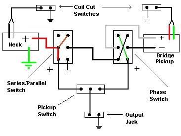 Note also that I've drawn a second "funny color" line in your ser/par switch (from the center-left terminal to the upper-right terminal). Even if you elect to not use my scheme, remember Unklmickey's advice about "points of failure". In a switching scheme such as you've drawn, it's simple for a viewer to dope out the action, but in point of fact, there are two switching elements in that series connection, whereas only one is needed. That extra element is what The Unkster was on about, remember? I like your more detailed drawing, except for the output jack - it's a bit hokey with that crook hanging out there.... May I suggest that you either drop that entirely, or else that you orient it more like a real jack, and put the hot lead on it, instead of the grounded sleeve? Just a thought. HTH sumgai |
|
|
|
Post by JohnH on Oct 16, 2009 5:00:22 GMT -5
Theres lots of ways to do these! I also think it is better if the toggle switch is completely bypassed in series mode, so you don't have two things to fiddle with. I also like to keep the functionality of the separate volume controls for each pup, and normal pot wiring so the output is taken from the centre lug. So in my version, the whole package of pickup, tone and volume pot is kept together and put either in series or parallel with the other: JH's JP wiring It also has no coil shunts or hot-hangs. Short of active buffers, the key to it is the treble bleed components. John |
|
|
|
Post by wolf on Oct 17, 2009 1:33:52 GMT -5
Well, thanks for the suggestions. Okay sumgai, your comments about the output jack were taken to heed.  Yes that's the latest incarnation of the JP wiring (and I hope it is mistake free). I was thinking of employing both of sumgai's suggestions, until I read John H's posting about using the series / parallel switch to bypass the pickup switch and have the series setting have both pickups in series in spite of the pickup switch selection. I've looked at John H's diagram but haven't been able to figure it out. |
|
|
|
Post by wolf on Oct 19, 2009 18:47:29 GMT -5
Okay, I've made my own attempt at connecting the series / parallel switch so that in series mode, the pickup switch position makes no difference.  I think it works out pretty well except that in the parallel position, the bridge ground connection is unconnected and therefore will not work. Any advice on this? |
|
|
|
Post by JohnH on Oct 19, 2009 20:12:55 GMT -5
Wolf - it needs a different arrangement of lugs to work with a dpdt. On my versions, I have bridge ground going to a pole, which switches it to either ground(P) or to neck hot(S). Neck ground is ground, Bridge hot goes straight to the bridge-side of the toggle
The other pole of the s/p switch is on the neck-side of the main toggle, and either connects it to the neck hot (P) or to the bridge side of the toggle (S). So in series mode, the signal still goes via the main switch but this switch is shorted across so that it makes no difference which position it is in. Any other way of doing it that I have tried seems to need three poles.
cheers
John
|
|
|
|
Post by wolf on Oct 19, 2009 23:05:39 GMT -5
Hi JohnHWell, if I have followed your instructions correctly it should look like this:  Anyway, that seems quite a switching discovery you made and I won't use it when I post the Jimmy Page wiring on my website. Any other way (as you said), requires another pole (such as the diagram in my previous posting). |
|
|
|
Post by JohnH on Oct 20, 2009 0:04:48 GMT -5
Hey Wolf, thanks but feel free to use it if you wish. It is the right way to do that switch, and in any case I think i saw it somewhere else first.
John
|
|
|
|
Post by wolf on Nov 13, 2009 23:15:19 GMT -5
Well, I finally finished my website page about this wiring: www.1728.com/guitar9.htmI would have finished this a lot sooner but I kept thinking of all the problems this could create. (For example, push pull DPDT pots don't work in a Gibson SG - it's too thin). |
|


 ) Let us know the results of the first two steps, and we'll all take it from there.
