|
|
Post by newey on Dec 28, 2009 7:13:08 GMT -5
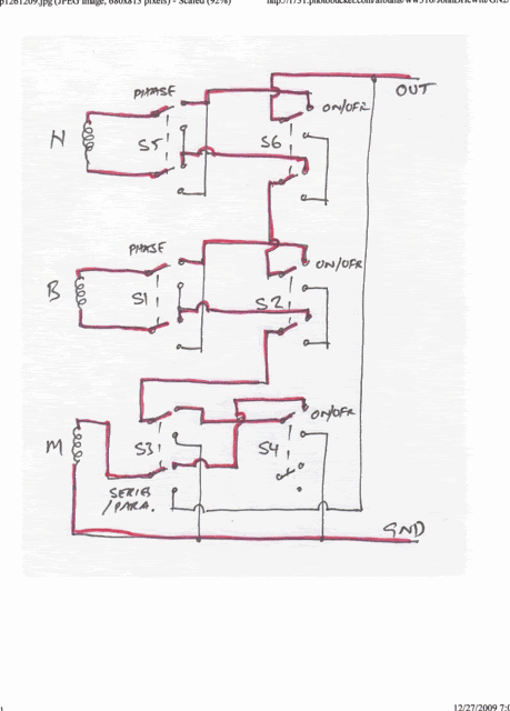
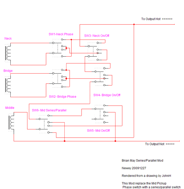
Killheart7 asked about modding a Brian May guitar to give parallel tones. The standard Brian May guitar features three SC pickup wired in series, with 6 DPDT slide switches- one on/off for each pickup, one phase switch for each pickup. Killheart decided he wanted to go in a different direction and get all possible parallel tones from his Brian May, by adding a 4PDT switch. JohnH provided a diagram to do so. Here's a link to that discussion: guitarnuts2.proboards.com/index.cgi?board=wiring&action=display&thread=4641My simpler idea was to eliminate the middle pup's phase switch, since the remaining 2 phase switches will give all possible phase combos of 3 pickups. The former phase switch then becomes a middle pickup series/parallel switch, giving 3 added parallel combos- N+M, B+M, and (B*N)+M. This avoids any alteration to the guitar's looks and involves no added hardware (well, some extra wire, perhaps!) EDIT: However, it does have a dead position when the Mid series/parallel switch is set to parallel and neither the N nor B is selected. This gives an all-off condition. This can be useful (to leave a guitar plugged in onstage w/o noise) or a curse (going dead in mid-song), depending, YMMV. Of course, this particular guitar already has an all-off position, since each pickup can be individually switched. This mod just adds a second one, so maybe not such a big deal. END EDITI asked JohnH to vet my first drawing, which had issues, and he responded with this hand-drawn version, which uses the red lines to demonstrate the default series wiring path. Below that is my redrawing for clarity, minus the red lines (well, actually, in mine, they're all red!).   I post this here for future reference for any further Brian May Guitar fans. And thanks to JohnH for lending his expertise to this. |
|
sci4us
Apprentice Shielder
 
Posts: 27
Likes: 3
|
Post by sci4us on Nov 6, 2019 23:37:24 GMT -5
Sounds like a good wiring scheme. Is the schematic still available? It is blurred out from Photobucket when I try to view it...
|
|
|
|
Post by newey on Nov 7, 2019 21:50:19 GMT -5
Yes, several years ago our forum fell victim to the bean counters at Photobucket, which now holds all our content hostage unless we all pony up the $$. And my copies were on a long-ago hard drive that went up in smoke at some point . . . I will see if perhaps our tech gurus can find a copy to repost; failing that, I'll have to redraw it, which may take some time. IOW, "Please stand by . . . "  Oh, and:
Hello and Welcome to G-Nutz2! |
|
sci4us
Apprentice Shielder
 
Posts: 27
Likes: 3
|
Post by sci4us on Nov 8, 2019 2:09:45 GMT -5
Hey there! Thanks for the welcome! So that's what happens, they privatize your own intellectual property, got it. Thanks for responding and thanks for the resource of wiring advice!
|
|
|
|
Post by newey on Nov 8, 2019 9:00:02 GMT -5
Looks like the schematic has been restored now, but if you still cannot see it, please let me know.
|
|
sci4us
Apprentice Shielder
 
Posts: 27
Likes: 3
|
Post by sci4us on Nov 8, 2019 22:03:07 GMT -5
Thanks for your attention, but it does appear that any picture with "Photobucket" on it is blurred out. It's okay. I'm looking for doing the wiring from scratch when I do, so it can be any one that will do series/parallel, on/off for each pickup (3 single coils of course) and the phase. I noticed that some say you need 1 less switch than the number of pickups to do all the phasing, as you need 2 pickups or more to have any phasing done (duh, right? lol).
I'm happy to see any existing, or otherwise available, pictures/drawings/files that you or any other folks would have, and I would even donate/purchase from you, should that be necessary.
Please let me know, in whatever way you can, whether it be through the messaging option, replying to the post, or if you even wanted to e-mail me, I would provide any such details, just tell me what I need to do, and I'll do it.
Thanks again!
|
|
|
|
Post by JohnH on Nov 9, 2019 0:17:58 GMT -5
Quick workaround for posts with blurred PB pix: try looking at them on an Android cell phone! works for me anyway...
As for the series/parallel schemes, we have a few, and I think you have found the main ones now.
|
|
sci4us
Apprentice Shielder
 
Posts: 27
Likes: 3
|
Post by sci4us on Nov 9, 2019 19:51:31 GMT -5
Looking on Android phone does help for some of it. Thanks!
|
|
fabian1993
Rookie Solder Flinger

Posts: 2
Likes: 0
|
Post by fabian1993 on Nov 27, 2019 11:19:26 GMT -5
Ahoi. I'm Fabian from germany and new to this Forum. I wanted to say thanks for this good idea. I am not good in electronics, so I had never come up with this by myself. I want to build a Red Special this winter, so I did a hand drawn wiring diagramm of your plan. Just because it's easier to read while soldering. So here it is, I hope it's correct:  |
|
|
|
Post by reTrEaD on Nov 27, 2019 13:40:06 GMT -5
Hi fabian1993 Schematics are easy to follow when working out a new idea, but a wiring diagram is generally easier to follow than a schematic (when doing the wiring) so I'm sure newey will appreciate your contribution. I don't have the time available to check it, but here's a copy of the schematic from the OP for anyone who has the time to compare them.  |
|
|
|
Post by newey on Nov 27, 2019 16:43:52 GMT -5
UGH!
Now that RT has reposted my 10-year old schematic, I'm not sure it is correct, despite JohnH vetting it for me.
As I look at it now, it appears that the middle pickup on/off switch does not turn the middle pickup off when set to parallel- the mid is always on in parallel mode. But it's been a long day, so let's get another set of eyes on it.
Fabian, sit tight for awhile, let me see if we can work this out. If my original schematic is wrong, then your diagram is likely wrong as well.
|
|
|
|
Post by JohnH on Nov 27, 2019 18:51:39 GMT -5
Hi newey, what you note is right, but I think that's just a natural consequence of your simple but clever mod. The basic range is still in the series mode, where you can switch anything on or off at will. The parallel mode just adds three key parallel combos, all of which include M. So you'd only go there to use those tones, but generally stay in series mode.
To get a full range of parallel options, plus singles from both modes, it needs the more complex circuit with the 4-pole series/parallel switch.
|
|
|
|
Post by newey on Nov 28, 2019 9:00:41 GMT -5
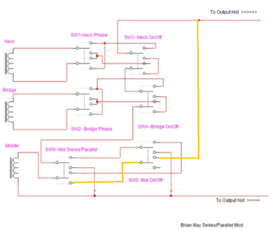
As I noted from the outset. this design does have a "dead spot" when the mid series/parallel switch is set to series, but neither the B nor N pups are "on". And I think the mid on/off switch works fine in the series setting. And, I take John's point about the use of the parallel switch. But it would still be preferable, I think, that the mid on/off also turn the mid pup off when in parallel mode- so the on/off switch operates just like the other on/off switches, no "gotcha" positions. Note that only one pole of the mid on/off is used, it looks to me that the other pole could be used to turn the mid pup off when set to parallel on the S/P switch. So, I revised the schematic, the orange lines represent the changes. Would this work?  fabian, if this checks out, I will do a wiring diagram for you to follow. I won't redraw the whole thing, as the wiring for the N and B pickups is the same as the original BM guitar (and your diagram has that correct). Since the mid pup wiring is the only thing that changes, all you need is a module showing those two switches, together with the in/out connections to the rest of the diagram. |
|
|
|
Post by JohnH on Nov 28, 2019 15:51:36 GMT -5
Yep that seems ok to me!
The series-parallel switch could be thought of as having 'normal' and 'Middle parallel' modes, whereupon it brings in three humcancelling settings (if M is RWRP) with M in parallel, or with this 2.0 upgrade, leaves B and N series or single combos if M is off.
|
|
fabian1993
Rookie Solder Flinger

Posts: 2
Likes: 0
|
Post by fabian1993 on Dec 9, 2019 14:50:38 GMT -5
Nice to see that my post got this thread back to life! Am I correct with that the 2.0 version will allow every parallel combination (NM, MB, NB and NMB)? I'm looking forward to see the wiring diagramm!  |
|
|
|
Post by newey on Dec 9, 2019 23:20:08 GMT -5
No. This simply adds the mid pup, in parallel, to whatever else is selected. The N and B remain connected only in series (between themselves, that is). So, you will get N + M, M + B, and M + (N X B). You will also get various OOP options, in series or parallel, depending on the setting or the remaining 2 phase switches.
I have a hand-drawn diagram in my briefcase at work, I need to get it home to redraw it and post it.
|
|