|
|
Post by roadtonever on Jan 16, 2011 5:21:53 GMT -5
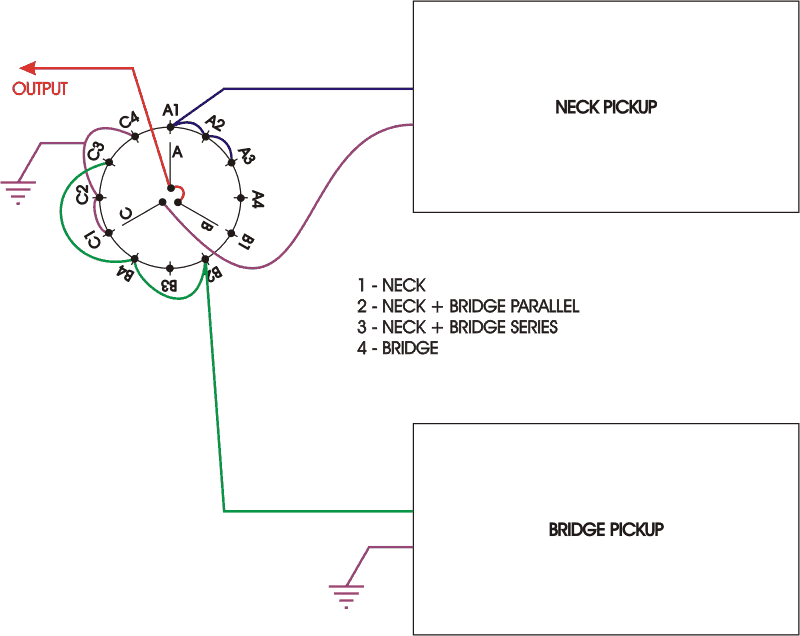
I want to wire a 4-pos. rotary pickup selector follow this diagram:  The problem is that I can't tell which lug is A and A1. Here's a shot of my switch:  Any help? EDIT: Resized the switch shot. |
|
|
|
Post by newey on Jan 16, 2011 9:04:48 GMT -5
You're going to have to get out your multimeter and check it. I use a tiny dot of nail polish or a paint pen to mark the various poles and their corresponding lugs, a different color for each group.
Also mark the #1 lug (based on your testing with the control either all CW or all the way CCW, your choice). you can use 2 dots for that one to distinguish it.
|
|
|
|
Post by roadtonever on Jan 16, 2011 10:03:57 GMT -5
I need some more direction on the testing procedure using a multimeter.
|
|
|
|
Post by newey on Jan 16, 2011 10:39:12 GMT -5
Connect one lead of the multimeter to pole "A" (arbitrary designation). Turn the rotary all the way clockwise. Then touch the other lead of the meter to each outside lug in succession. A reading of "overlimit" or infinite resistance indicates no connection, a reading of 0Ω,or a very low resistance, indicates a connection between that pole and that outer lug. Mark the pole and the lug, move on to pole "B" without moving the rotary, find "B1" to correspond with "A1". Then check Pole C the same way. Once you get A1, B1, and C1 marked, the other positions just fall into place, but check them just to be sure, by moving the rotary one click for A2, B2, and C2, etc.
It is best to check all components with a meter prior to wiring, a bad pot or a bad switch will leave you scratching your head for weeks, as you check and recheck all your wiring connections.
|
|
|
|
Post by ashcatlt on Jan 16, 2011 11:10:54 GMT -5
newey's got you covered for the test procedure. These are open on the sides and you can sometimes just look in there and see what's happening, but the meter is still probably best.
That's a 3P4T switch, there, though.
|
|
|
|
Post by wolf on Jan 16, 2011 14:28:19 GMT -5
roadtoneverNot to promote my site any further, but if you go to this page: www.1728.com/guitar10.htmand scroll to the second diagram, you will see a Series Parallel switch that requires only a DPDT switch and is a heck of a lot easier to wire.
|
|
|
|
Post by sumgai on Jan 16, 2011 14:35:37 GMT -5
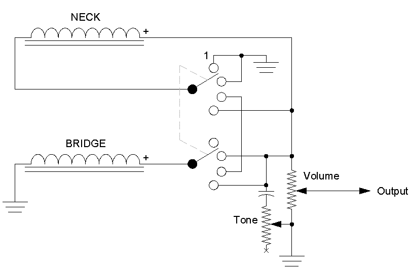
rtn, Note that I'm not criticizing this circuit in any way, but the possible combinations are what's known as "The Baja Tele". Fender made a Telecaster that has the same 4 pickup possibilities as your diagram, but they used a standard 3-position Tele-style switch, modified only to give it one more position. But more important here, for our current discussion, is the fact that the modified switch still has only two poles..... or in other words, Fender achieved all four possible combinations with only two poles - the third pole is not necessary at all. All of that leads to the question - are you using the 4-position rotary switch because you believe you must use it? Or are you open to using other switch types? Regardless of the answer to that question, just know that the same switching diagram can be used with both switch types. In case you're interested, here's the schematic:  HTH sumgai |
|
|
|
Post by roadtonever on Jan 17, 2011 8:14:32 GMT -5
Thanks newey and everyone else chiming in! I'm converting a two single-coil pickup bass from vol-vol-tone to mastervol-pickupselect-tone. I decided on a rotary solution for series/parallel so I don't have empty holes in body or end up filling them with reduntant (for me)controls. Volume and tone will be push-pull reserved for other functions(out-of-phase and inductor respectively). Later on I plan on adding a 3-pos mini switch with resistors wired to the lugs for simulating the tone responce of 500k, 250k and 125k pots. Naturally, I have no idea how to go about it. Would it go between switch-out and vol or vol and jack. I'm not sure what mini-switch type to get and how to wire it. I suppose starting with actuall 500k pots is the easier way to go about it? This is the basic wiring diagram I'm using: homepages.ihug.co.nz/~online/nocaster/blqfilterwiringdrawnbyvito.jpgGrateful for any ideas. EDIT: Here's a shot of the bass. Note the pickups have been replaced since I took the picture.  |
|
|
|
Post by cynical1 on Jan 17, 2011 11:19:02 GMT -5
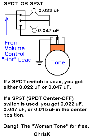
I'm converting a two single-coil pickup bass from vol-vol-tone to mastervol-pickupselect-tone. I've had two single coil pickup basses for years, and I would caution you about the selector switch. For example, you want a thicker bass tone, so you crank the neck to 10. The two volume controls will allow you to add just enough of the bridge pickup to kill the hum. The neck on its own is gonna hum without a little of the bridge in there. Works in the inverse when selecting a more jazzier bridge tone. I did the pickup selector switch mod to a Jazz bass clone and it lasted just about long enough to plug it in, test it...and de-solder it. With noiseless pickup it works fine, but with single coils you might not be as pleased with the end result. I would suggest you check out the Free Woman Tone.  Works the same for bass as it does for guitar. Nice looking bass, BTW. Happy Trails Cynical One |
|
|
|
Post by roadtonever on Jan 17, 2011 13:04:03 GMT -5
Thanks for your ideas cynical1! The pickups are infact noisless singles. I lost interest in blending actions since the last pickup replacement, to me the tone less pleasing unless one or both pickups are full up. I think ChrisKs free woman tone is neat, thanks for reminding me about it!
Oh, I better quit stalling and get out the multimeter....
|
|
|
|
Post by ashcatlt on Jan 17, 2011 13:35:40 GMT -5
The thing with the mini-switch would work with a DPDT on-off-on. You'd have 500K in the middle position and your other values to either side. You'll have to decide if you want the effect of both V and T being reduced, or just one of them, or just pick values that sound right to you.
This is pretty much redundant with the tone control, though. The woman tone thing is likely more useful.
|
|
|
|
Post by JohnH on Jan 17, 2011 14:35:47 GMT -5
This is pretty much redundant with the tone control, though. The woman tone thing is likely more useful. Agreed. Useful factoid: The tonal effects of changing to lower pot values can be exactly matched by turning down the tone control - to within a fraction of a db. |
|
|
|
Post by roadtonever on Jan 26, 2011 21:47:57 GMT -5
It's 1,5 weeks later with a visit to a friend in Stockholm in between and I'm at least making SOME progress.  Alas, the spindle broke to pieces while using pliers to pull it in place. Won't try that again. Did someone say low grade pot metal?  The tone control I use has an 3H inductor in place of the usual cap, with a switchable series cap (.1uf)which preserves lows. This setup works great for me as I like to keep as many high frequencies as possible and does 85% of what a standard tone does. Controlling the height of the treble peak by varying series resistance via switch sounds like a good idea in my head, bypass for hard-rock, max for jazz etc. Of course reality is another matter and I'm always open to ideas. BTW Has anyone made a 2PU,1V,1T&Sel. diagram that I can that I can reference for proper ground connections? My bass is unshielded. |
|
|
|
Post by newey on Jan 26, 2011 22:04:55 GMT -5
Since you indicate it has noiseless SCs, there's probably no benefit to shielding it, if you were going to do so. I'm sure there is such a diagram around here somewhere, but most diagrams omit the grounds, since these are understood to all collect at a grounding point, whether the back of one of the pots, or a screw into the side of the cavity or whatever you use. Since you are doing a series wiring, the ground from one pickup will go to the rotary, as shown by your diagram. The other pup goes to the grounding point. Your grounding point, whatever it is, will collect the following wires: - The string/bridge ground wire.
- The output jack barrel (or "sleeve") connection.
- The one grounded end of the one pickup.
- The ground from your rotary, as shown.
- The grounds from the V and T pots; in the case of the tone pot, this will be through the inductor/cap set-up you have.
- Optionally, you may want (or need) to ground the backs of the pots for noise issues, and possibly the frame of the switch.
Hope that helps. |
|
|
|
Post by roadtonever on Jan 26, 2011 22:41:21 GMT -5
Most helpful reply, Newey! This answers many questions I had.  |
|
|
|
Post by roadtonever on Jan 28, 2011 21:21:47 GMT -5
Today I transplanted the outer lug board of my broken switch to another identical one. Soldered the pickup leads and connected the switch directly to the jack. At first no output, prodding revealed lack of contact between inside pins, opened it up and andgled the inside pins for better contact and made sure all parts fit snugly. We have output! But only pos. 1 and 3 are functional and pos. 3 outputs only the bridge pickup(checked by tapping poles w/ screwdriver). I'd admitt sodering the wires on the switch was rushed. Prodding wires and contact points within the switch doesn't reveal anything. Any suggestions? Start over? Get a different make of switch? ;D
|
|
|
|
Post by ashcatlt on Jan 28, 2011 23:24:50 GMT -5
Assuming that you identified the switch lugs correctly , the switch wiring looks fine. Of course, I can't see the pickup wires... I just now checked the diagram itself and it appears to work, though the C4 connection is unnecessary. The screwdriver test is nowhere near as useful as measuring DC resistance across the jack. Of course, this works best if you measured (and recorded) all of your components before installation. Which pickup functions in position 1? I use those Alpha switches all over the place. Only time I had a problem (so far) is when I tried to force it to turn further than it wanted to. I wasn't sure where it was when I started, or miscounted, or something...  |
|
|
|
Post by roadtonever on Jan 29, 2011 0:50:12 GMT -5
Which pickup functions in position 1? Neck pickup, turned fully clockwise looking frombelow, the pos. functioning as it should. Thanks for letting me know about the redundancy of C4. Following JohnH instructions I located the pins with my multimeter and marked them. Wire location has been quadruple checked. Maybe internal contact points have failed due to stress from the transplant. Or maybe I made a misstake locating the right pins, 'though It seemed fool-proof. I'll do some more troubleshooting tomorrow, like nudging more than one contact point at a time. Then If nothing else I'll redo the switch wiring. Maybe testing the connections with alligator clips first...  |
|
|
|
Post by roadtonever on Apr 9, 2011 6:31:05 GMT -5
Two quick questions:
I want to add series resistors active on the parallel setting(#2) only. Which pins would these go to?
I have two switches, shorting and non-shorting. Which would be preferable?
|
|
|
|
Post by ashcatlt on Apr 9, 2011 11:28:41 GMT -5
You want resistors in series with what? I can see where we could get it in series with the neck pretty easy, but I'm not sure exactly what you're doing (or why, but I'm willing to assume you have good reasons) so I'll wait to offer that.
Shorting/non-shorting refers to how the switch acts as you're switching. Sometimes referred to as "make before break" or "break before make" respectively. It shouldn't make any meaningful difference here.
|
|
|
|
Post by roadtonever on Apr 9, 2011 12:35:57 GMT -5
|
|
|
|
Post by ashcatlt on Apr 9, 2011 12:43:11 GMT -5
Replace the jumper from A1 to A2 with the Neck pickup resistor. Move the jumper between A2 and A3 so it goes A1 to A3.
Make the bridge go directly to B4, and replace the B2 to B4 jumper with the bridge resistor.
|
|
|
|
Post by roadtonever on Apr 10, 2011 14:31:19 GMT -5
Many thanks, Ashcatlt!
|
|