|
|
Post by sbgodofmetal on Apr 9, 2011 13:20:05 GMT -5
parts,
3, electrolitic caps, (1)10uf, (1)22uf, (1)47uf
1, film cap, 4.7nf.
1, resistor, 47k
4, resistors, (2)10k (2)100k,
1, potentiometer. 5k
1, 3 prong transistor
|
|
|
|
Post by JohnH on Apr 9, 2011 15:31:02 GMT -5
Thats a great little project, lots to learn from that. Here's a thought. If you have a laptop or pc available (are you posting from a mobile device?), why not model that circuit in 5Spice? Its free, and very easy to use. You build that diagram using drag and drop commands, then run it, and you can check out its gain, frequency response, see how it clips etc. Then you can play with the values - extend it etc - see what the voltages are at each point www.5spice.com/Im sure you can get great help on that on the DIYS forum, but let us know if you need anything here. John |
|
|
|
Post by sbgodofmetal on Apr 10, 2011 15:17:08 GMT -5
thanks john yes sadly i'm still mobile i have limited access to our laptop b/c the misses wont let me on it anymore and she gets highly upset if i down load anything but i'll try to see what i can do with it later. that schem was copied from www.DIYstompboxes.com all i did was draw a copy for my assembly reference but there's was just a simple booster what i did was change cap values on the input from .1uf to 4.7nf to make it a treble boost, kinda easy conversion |
|
|
|
Post by thetragichero on Apr 11, 2011 16:15:28 GMT -5
yes i would hold off on any sort ring modulator/octave pedal until you've got a few under your belt
i made the ampeg scrambler as my third build... was too complicated to breadboard so i just made it on perf and hoped for the best
to deal with the low level from the pedal, i put a footswitchable fetzer valve after it
definitely useful, use it on about half of my band's songs for a nice boost/texture
look up schems for the brian may treble booster... i made one and it's killer. i swapped the 10k pot for 50k and it gives a TON more gain on tap
i hope you know you're messing with some pretty hard stuff.... you'll be needing to go to AA meetings for pedal building soon enough!
|
|
|
|
Post by sbgodofmetal on Apr 12, 2011 11:49:53 GMT -5
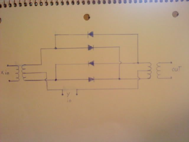
i was thinking of doing this  i really want a ring modulator but cant afford to buy one so a DIYversion is my best option monetarily |
|
|
|
Post by sbgodofmetal on Apr 12, 2011 11:57:26 GMT -5
i just copied this schem, so i'm a little unsure about it, so what are those curved things on either side and how and were would i need to put potentiometers for level depth and width, and weres the power input go??
|
|
|
|
Post by thetragichero on Apr 12, 2011 12:13:17 GMT -5
those are transformers/inductors i've heard good things about the green ringer... no need to reinvent the wheel just yet (get a few under your belt first  ) |
|
|
|
Post by ashcatlt on Apr 12, 2011 21:08:28 GMT -5
I have to apologize if I've led anyone to believe that I've ever actually built a ring modulator! I've used a couple, but most had active circuitry, or were digital emulations. That schematic really is all you need for the passive implementation. Three jacks, two transformers, and four diodes and you're done! Unless you want a switch, I guess. There's no power necessary since it's passive. Unless you want an LED to go with your switch. There are no controls. You might (?) could put a "Mix" knob to get a little blend of X and/or Y into the output. Here's a link to a page that will sell you one, but also has links and part numbers for the transformers and diodes. Now, I want to make sure you understand a couple things about this circuit before you go hacking it together: 1) This box requires two inputs - labeled X and Y in your diagram. The output will be X times Y. My first grader will tell you that if X or Y equal zero, then the output also must also equal zero. If you just plug your guitar in and then out to your amp you'll get nothing.* 2) This circuit requires two fairly high voltage inputs. They have to be able to overcome the forward voltage drop of the diodes in order to get any output. Even the low V f in diodes like germaniums and shottkys are difficult for most passive guitar pickups to overcome. It will most likely require some form of boost beforehand.** 3) Ring Modulation is notoriously unpredictable and quite strange. The output is highly dependent on the mathematical relationship between the two inputs, and not often very musical sounding. Most musicians (as opposed to noise freaks) who end up building or buying a ring modulator for guitar purposes play with it for a couple hours and then realize that it has very limited practical use and never touch it again. * It would be possible to build a simple oscillator in to act as one of these inputs. ** The DIYSB Beginner Project would probably work for this. |
|
|
|
Post by sbgodofmetal on Apr 12, 2011 22:02:03 GMT -5
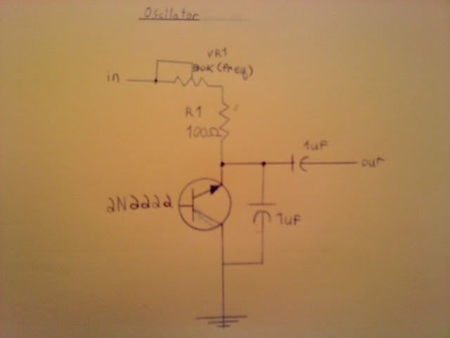
will this work?  that VR1 is marked B10k (freq) sorry for its illedgability. |
|
|
|
Post by sbgodofmetal on Apr 12, 2011 22:47:18 GMT -5
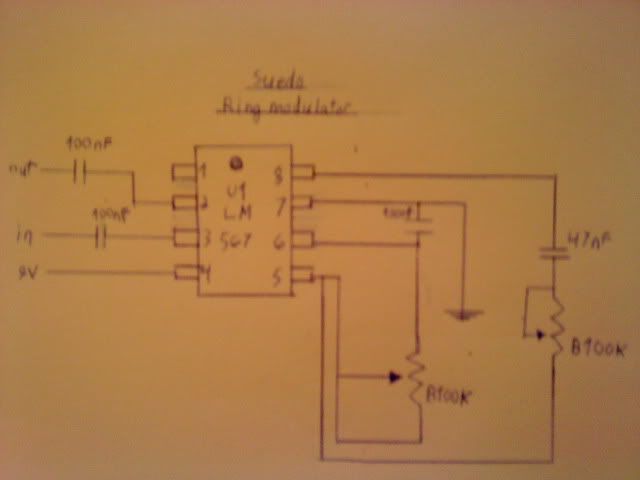
theres also this alternative i found  its a suedo ring modulator, and seems simple to do, so i'm thinking of actually doing this one instead of just talking about it. but just so im clear on this the zig zag lines that normally represent resistors ARE potentiometers when arrows are pointing at the peaks, right??? |
|
|
|
Post by ashcatlt on Apr 13, 2011 0:20:29 GMT -5
Yep, those are pots.
Do it! I don't know what that 567 thing is gonna do, but I want to hear it. Got a breadboard yet?
|
|
|
|
Post by ashcatlt on Apr 13, 2011 0:33:24 GMT -5
BTW - if I can be forgiven for a bit more advice that I have yet to heed:
A great first project would be a prototyping box. I'm envisioning something like a metal box with hinges - like the "moneybox" we use at the door at gigs - with some jacks and pots installed.
The breadboard can then be placed inside a shielded enclosure for testing. The big problem I have in testing the high gain circuits I've been building is that my "workbench" is also my computer desk, and if I want meaningful audio, I have to have to have two machines running. It's sometimes difficult to hear what's happening to the guitar signal under all the radio stations and random noise!
You'll need wires (solid core is preferable here) from every lug on those jacks and pots so they can attach to the breadboard, and that's some pretty good soldering practice.
Next step would be to build in a filtered and maybe regulated and (even better) variable power supply. Bonus points for buffered variable multiple-tap PSU with short-circuit protection!
|
|
|
|
Post by sbgodofmetal on Apr 13, 2011 9:26:01 GMT -5
ok i've seen a simplistic version of that variable power supply w/cc protection normally i'd draw it and post about it but my girlfriend is running late for a dentist appointment and i'll try to do so this evening. ;D oh and ash i cant wait to hear it either, i'm also glad to report i'm learning schematics very quickly too....  |
|
|
|
Post by thetragichero on Apr 13, 2011 13:19:02 GMT -5
i used to be scared about schematics, now i prefer posts to include them... certainly aids in troubleshooting when you can see the logical relationship between components!
|
|
modusmongo
Rookie Solder Flinger

Posts: 12
Likes: 0
|
Post by modusmongo on Apr 13, 2011 14:49:54 GMT -5
Kudos sbgodofmetal! This post has inspired me to start a small DIY project. I keep asking questions on this forum because I want to get things working, but really, I could answer most of those questions myself if I knew how to read schematics and understood the interaction between electric components. Building a simple circuit is a way to learn by jumping in.
Hmmm, I think I'll start with a wah compressor delay ;-)
|
|
|
|
Post by sbgodofmetal on Apr 14, 2011 7:26:11 GMT -5
i haven't saved up the money for all of my parts yet i estimate having all i need by the end of may (god willing). and to tell the truth modusmondo until 4 days ago i couldn't read much less understand schematics until ashcatlt pointed me to the beginners project at diystompboxes.com that is a simple boost pedal and they break each schematic symbol down and explain what it is i'd recommend starting off with something simple like this. its a good way to get started.  |
|
|
|
Post by sbgodofmetal on Apr 14, 2011 7:34:29 GMT -5
modus you may also want to look at my thread about passive fx theres a few neat things in there. oh and ash since i notoriously buy in bulk i'll be toying around with these mixing and adjusting i'm in the process of drawing a schematic combining the oscilator circuit with that suedo ring modulator, and i just noticed your other comment and i'll try the oscilator on the booster as well i've got a simple distortion schematic i'll be posting in just a few moments for discussion so thanks for all the help guys
|
|
|
|
Post by sbgodofmetal on Apr 14, 2011 7:40:30 GMT -5
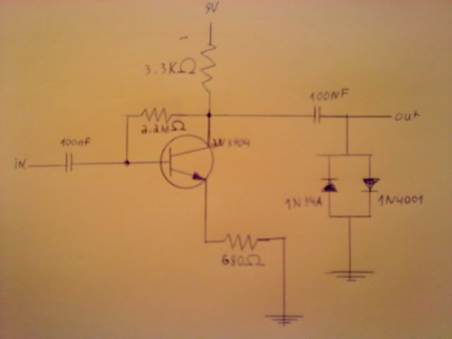
 just a few things here i cant see anything resembling a pot in this circuit but i'm still learning these as i go so im hoping that one of these resistor symbols is one but with no obvious arrows i cant tell another thing is this seems to me atleast to be reminiscant to johnh's diode clipping in an active form ;D cant wait to hear these either |
|
|
|
Post by sbgodofmetal on Apr 14, 2011 8:03:07 GMT -5
hey ash that 567 thing is called a tone decoder chip. i'm really not sure of what it was either and to be honest at first i thought it was just another value of OpAmp, good thing i double checked again.
|
|
|
|
Post by ashcatlt on Apr 14, 2011 10:45:17 GMT -5
I don't see a pot anywhere in that distortion schematic either. If you wanted adjustable gain knob, I think you'd put it in place of that 680R to ground, possibly with a cap, exactly like in the boosters.
In fact - as you seem to have recognized yourself - this is just a booster followed by a diode clipping section which works exactly like those in JohnH's passive clipping thing. There might end up being some distortion from the transistor stage, if it's asked to produce enough gain, but for the most part the clipping here is purely passive.
|
|
|
|
Post by sbgodofmetal on Apr 14, 2011 11:44:10 GMT -5
quick question? the oscilator schem i posted is it purely passive as well? i'm thinking it was a fragment of a bigger schem, showing how that particular segment was to work or something.
|
|
|
|
Post by ashcatlt on Apr 14, 2011 11:51:11 GMT -5
Yeah, the oscillator is active. Can't get something for nothing, you know! Pretty sure the "In" on that scheme needs to be some DC voltage more positive than the ground connection.
|
|
|
|
Post by sbgodofmetal on Apr 14, 2011 12:04:12 GMT -5
i'm curious, if i connect the oscilator circuit directly to the booster, would it go to the input or the output of the booster? and would the power to the booster be enough to power both transistors through the one place or will i need to run hot wires to both?
|
|
|
|
Post by ashcatlt on Apr 14, 2011 13:22:09 GMT -5
Are we still talking about the passive ring modulator?
You will almost certainly need to run your guitar through a booster and from there into one of the ring mod ins. Let's just say Input X. You will run the oscillator into input Y. Since I don't know how to calculate the output voltage for that osc, I can't tell you whether it will need a boost before it gets to the ring mod. My guess would be likely not, but if it does you'll be running it through another booster in the same way you do with the guitar.
The boost and osc will each need DC power supplies.
|
|
|
|
Post by sbgodofmetal on Apr 14, 2011 14:00:05 GMT -5
i was refering to wiring the active oscilator into the booster on the board making one big wierd effect (but i'm unsure as rather to wire it before or after the booster circuit) and would it inturn need 2 9volt sources or will one suffice???
|
|
|
|
Post by sbgodofmetal on Apr 17, 2011 22:02:51 GMT -5
Yeah, the oscillator is active. Can't get something for nothing, you know! Pretty sure the "In" on that scheme needs to be some DC voltage more positive than the ground connection. if it helps you to better explain this i went back and took another look at the original scheme and the input symbol was marked Vcc, what ever that means??? need help understanding this one. |
|
|
|
Post by ashcatlt on Apr 17, 2011 23:11:53 GMT -5
Vcc is usually the positive DC rail. The "top" of the battery. That circuit doesn't really have an audio input. It just oscillates. If you put it going to the input of the booster you'll get a louder version of it coming out. I don't know what will happen if you use its output as the power supply for the booster, nor if you use the output of the booster as it's power supply. Worth a try, anyway. Got that breadboard yet?
|
|
|
|
Post by sbgodofmetal on Apr 17, 2011 23:36:02 GMT -5
i'm working on aquiring that bread board as i posted the other day i'll have all i need by june. right now i'm in the process of packing i'm moving this week and between the high gas prices and my girlfriends trips to the dentist (2 broken and infected insizors, very painful!!!) my weekly income is pretty much spend before i even get it. i'm just merely gathering as much useful advice and info as i can before i pick up ye ol' finger burning solder iron.
|
|