|
|
Post by JFrankParnell on Apr 16, 2011 23:19:20 GMT -5
I was thing about the 'neck on' switch that is mentioned from time to time. How bout 'bridge on, in series' with what ever is coming out of the main switching scheme? On settings that normally have the bridge in paralel, eg N+B, would now become N*B and N+M would now become N+M*B. However, did I make the B soop? 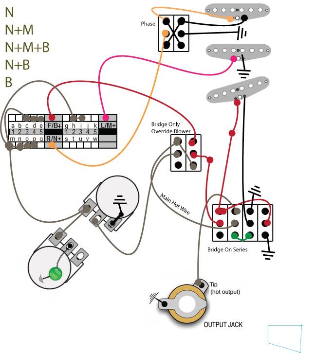 |
|
|
|
Post by newey on Apr 16, 2011 23:37:28 GMT -5
jfp- I see some issues. The 4PDT switch, when the 2 lower lugs are connected to make the series setting, disconnects the output jack from the circuit. In your series setting, with the blower switch "on" so that the pots are bypassed (and, with the output disconnected, as noted above), the Br. black wire eventually reconnects with the Bridge red wire, meaning that the pup is shorted to itself. That's 2, there may be more. . .  |
|
|
|
Post by JFrankParnell on Apr 16, 2011 23:51:41 GMT -5
ok, I think I fixed the jack wire 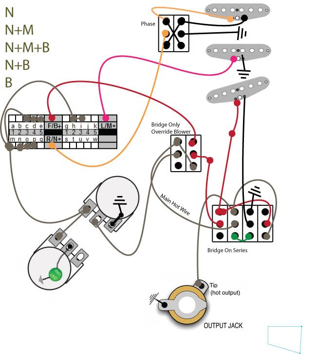 And, I can live with a conflict between the blower and the series switch, they are mutually exclusive. Do y'all think its best to keep revising the first post with new images or better to post revisions in the thread, like this post? |
|
|
|
Post by newey on Apr 17, 2011 0:41:55 GMT -5
It's more than a conflict, it's a distinct lack of output.  With the series switch down, you now have the Bridge red connected to the jack. The Br. black wire, however, connects to nothing in either position of the blower switch. If the blower is flipped to the V & T setting, the Br. black connects only to the volume pot wiper. In the blower position, it connects to the red wire, which leads back to the series switch, where the red wire is connected to . . . nothing. I don't see why you are wiring the output jack into the 4P switch. What are you achieving by doing that? |
|
|
|
Post by JFrankParnell on Apr 17, 2011 11:31:28 GMT -5
hmm, ok, lets back up a step to a relatively normal set up, without the blower. As to why the output jack was wired to the 4p: well, that would have cut out the V and T. I dont think I want that, so I've moved the whole contraption to before the V and T. 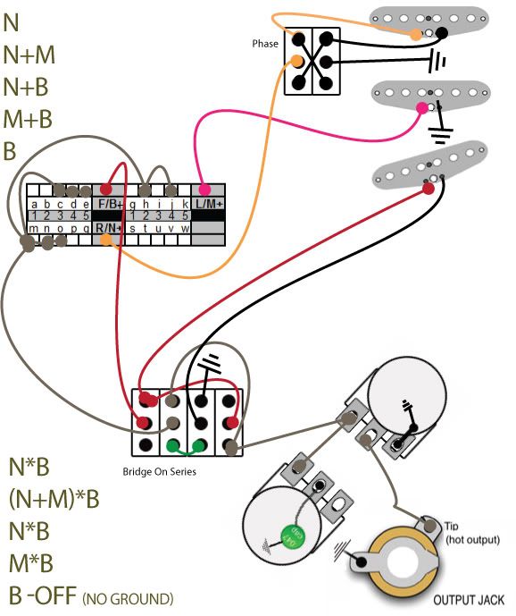 (it looks to me) With BOS (bridge on series) switch up (upper lugs connected), everything goes in its' natural flow. B+ makes it to the 5way, B- goes to ground, 5way output goes to the pots, With BOS down (lower lugs connected) the B+ doesnt go to the 5way, instead goes straight to the pots. The 5way+ now goes to the B-, thru the B pup, and out thru the B+. I think. Right? |
|
|
|
Post by asmith on Apr 17, 2011 13:16:22 GMT -5
JFP, Adding the Bridge in series with anything with a "Blower" switch was one of the goals on the mod I've almost completed on the Strat. It's a lot easier than you're making it out to be. You can do it with a standard, "8-lug" five-way switch, and only DPDTs. Try thinking of it like this. At the moment you have two "modules," 1) a Bridge pickup, and 2) the Neck + Middle pickup. You need a circuit that simply grabs that Bridge module and throws it in series with the Other module, whilst retaining the selector switch. Hopefully that's a little nudge in the right direction. Because I think almost everybody here prefers figuring out something for themselves, I'll just link to my solution here in case you want to take a peek. My schematic (which is really just a bastardisation of one of JohnH's) has two separate volumes, for "Neck + Middle" and "Bridge," and as such uses a concentric pot for the tone controls, but can easily be adapted into a master-tone, master-volume setup. |
|
|
|
Post by JFrankParnell on Apr 17, 2011 15:07:09 GMT -5
ok, well, I peeked ;D But, since I dont really read schems, it didnt feel like cheating too much  so, I came up with this 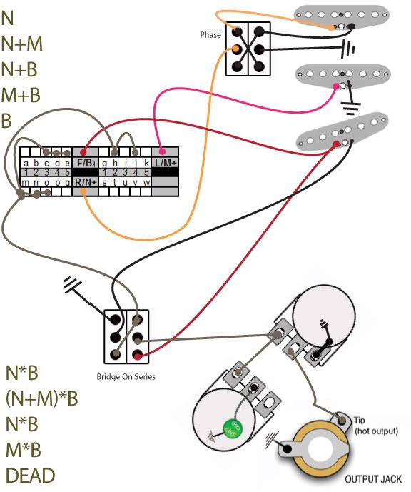 Indeed, this does seem to work with just a dpdt. I think I can probly fix that dead setting to normal B by using the 4th pole of the 5way, if you think I've got things correct otherwise. I figure I can still do a bridge blower override as an additional module to this. |
|
|
|
Post by JFrankParnell on Apr 17, 2011 21:50:47 GMT -5
edit: actually, I dont know if I can get B to work alone when series sw is on. That might be a dead spot, unless I use a 4pdt. 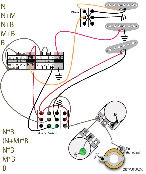 |
|
|
|
Post by newey on Apr 18, 2011 20:17:02 GMT -5
Jfrank- I think your translation of asmith's schematic is OK. You latest 4PDT diagram still ain't cuttin' it. All is fine with the 4P switch "up", in the parallel setting. Flipped down to series, however, and the Bridge red connects to the Vol pot (so far, so good . . .). The Bridge black goes, via the green jumper, over to the previously-unused pole of the 5-way, where it is grounded in position 5. That places the Br pup always on, but only at position 5 and in parallel, not series. The hot leads of the other pups are indeed shorted and not on at position 5- but they also don't connect anywhere in the other 4 positions. This layout thus gives you 4 positions of silence, and bridge alone at position 5. I hate to always be the bearer of bad news, jfp . . . |
|
|
|
Post by JFrankParnell on Apr 18, 2011 21:21:04 GMT -5
totally cool, Newey, that's why I do this in Illustrator, comfy in my office before going out to hunch over the bench in the cold garage But... I beg to differ... Firstly, thanks for the confirmation on the dpdt design. Do you concur that pos 5/series mode will be dead with no possibility of life? Cuz, I would rather use a dpdt as I have some of those cool rocker switches. But, I would give up the rockers if I had to, to get B working in series or paralell. Ok, now the differing. On the latest 4pdt design. Parallel is all good, ok. In series mode, pos 5, that black wire to pole 4 of the 5way is only there to provide a ground for the B in pos 5. I think you agree that series mode, pos 5 is correct. But, for the other 4 positions, the hot wire comes off the switch on the grey wire to Pole 2, middle lug. It then jumps (via green) to pole 3, lower lug. It continues on, (via pole 3, mid lug) to Br black. Exiting from the Br pup on the red, it arrives at pole 1 top lug, where it is jumpered around to pole 4 mid lug and then out to the pots via pole 4 lower lug. Ha, I typed that all out just so I was sure. I'm pretty sure. But willing to be corrected  |
|
|
|
Post by newey on Apr 18, 2011 21:37:06 GMT -5
You're right on the series connection, I missed that.
On the DPDT, position 5 is indeed dead. Whether that can be overcome with the DPDT, I'm not sure. Was asmith's dead at that position, I forgot to look?
|
|
|
|
Post by JFrankParnell on Apr 19, 2011 16:35:08 GMT -5
I cant really tell if asmith was dead at that pos. His is more complicated with blend pots and such. Ok, new idea: you see I have two identical settings with series on, 1 and 3 are the same. I was wondering if the 'special cap' from chrisk's s-none could be implemented: guitarnuts2.proboards.com/index.cgi?board=schem&action=display&thread=3153 but I'm unsure if the special cap is wired in paralell or series with the pups or what. I was thinking, on pole 4 of the 5way (currently unused), if that could be used to put in a special cap on either 1 or 3. |
|
|
|
Post by sumgai on Apr 19, 2011 18:27:17 GMT -5
newey, c1, It would appear that either my memory is Gingko/Biloba-proof, or else my Search-fu has slacked off dramatically. Can you help a brother out here? Didn't we just go through this exercise with rabidgerry and his single switch to do it all? I mean, I even lost a switch in the mail to him, yet I can't find a single reference to that whole topic/thread. Searching my PM's didn't help either, but then again, after 2K+ of the things, I can't blame the system for "hiding" anything from me. I swear, some days it don't pay to get outta bed.  sumgai |
|
|
|
Post by newey on Apr 19, 2011 21:37:49 GMT -5
Oh, you mean this thread here, Rabidgerry's 3 Mod Questions. This was the famous, dare I say infamous thread, which saw the abrupt departure of ChrisK (In conjunction with the outris thread), and in which numerous other members' tempers fray. In the end, at the bottom of page 6, rabidgerry produces a reworked version of ChrisK's "S-None" idea, using a 4P 3T switch. A bit different than what jfrank is up to here but pretty goldurn close. And rg has apparently built this beast and it works. Note that the integrity of this thread has been corrupted because ChrisK deleted at least one of his posts, as he left us in a huff. So, that part of the thread doesn't seem to make much sense, just be aware that some material was deleted, unfortunately. In the 6 year history of this board, as far as I have seen, there have only been 3 times where some folks got seriously p.o.'d here. This was one of those times, and may well have been the worst. Overall, I'd say our civility record is pretty good, though- 3 times in 6 years isn't much. But it is a bit of a cautionary tale, on several levels. First, we should always give credit where due when reproducing the work of others. And second, take a deep breath and remember it's only a guitar and we're all here for fun and enjoyment. And, check those egos at the door! Sorry, reading through that sad chapter again brought back a lot of stuff. For about a week or so back then, I thought our collective wheels were gonna come off. And, I largely blamed myself for not being able to mediate the thing more effectively. |
|
|
|
Post by cynical1 on Apr 19, 2011 22:31:34 GMT -5
And, I largely blamed myself for not being able to mediate the thing more effectively. I would have to respectfully disagree with you on that one, counselor. I think anyone that was here for that affair would all agree that the sequence of events could not have been predicted or prevented by anyone. If anything you showed much more restraint and judgment then I would have in your position. You're one of the primary drivers behind this forum being such a generous and respectful place. Don't beat yourself up over the tide going out. And yeah, I think that's the thread. HTC1 |
|
|
|
Post by JFrankParnell on Apr 19, 2011 23:50:53 GMT -5
ok, what i get out of that and looking again at s-none, is that the special cap is to be wired in series with the pups. what that means to me and this circuit is that it is not possible to have both: 1. bridge on in either series or paralel B. special cap on pos 1/series only i could have both of those if I used a 5pdt for the ser/par switch and ran the N- through it. In parallel, it would just go to ground, in series it would go either thru the cap, (on the way to lug S on the 5way) or straight to lugs T & U and then to ground. I do have a 6pdt mini slider... 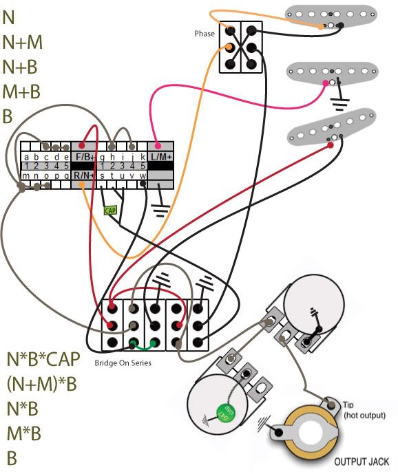 |
|
|
|
Post by sumgai on Apr 19, 2011 23:52:46 GMT -5
newey,
Thanks, c1's correct, that's the one I was looking for.
JFrank, I had forgotten about that particular episode. If you don't mind, we'll observe a moment of silence, in memoriam for our departed friend.
We'll all be right back after this slight time-out.
sumgai
|
|
|
|
Post by asmith on Apr 21, 2011 7:22:51 GMT -5
Let's all just hold the phone here. I have a few questions. 1)What are the goals of the design? For example, is this correct? | # | Normal Mode | Series Mode | | 1 | B | B | | 2 | B+M | B*M | | 3 | M | B*M | | 4 | N+M | B*(M+N) | | 5 | N | B*N |
Is there a cap wanted somewhere? 3)Do you want the Bridge pickup to go out of phase, or the Neck? 4)Do you have to use the superswitch? (Obviously if your goal requires the use of one, you do, but you might not need it). 5)I presume your guitar only has a master tone and master volume. Do you want push/pull pots? What's the aesthetic concerns here? I get the impression chrisk (sounds like a lubricant; "I'm going to apply some chrisk to my guitar") liked the 'modular design' approach. I think that makes sense. Implementing a phase switch is not a problem then. Then let's incorporate the 'Bridge in Series' switch. Then let's modify that if you want a cap in series anywhere. Then finally let's add the blower switch on. |
|
|
|
Post by JohnH on Apr 21, 2011 8:17:07 GMT -5
|
|
|
|
Post by JFrankParnell on Apr 21, 2011 10:38:43 GMT -5
Let's all just hold the phone here. I have a few questions. 1)What are the goals of the design? For example, is this correct? | # | Normal Mode | Series Mode | | 1 | B | B | | 2 | B+M | B*M | | 3 | M | B*M | | 4 | N+M | B*(M+N) | | 5 | N | B*N |
Is there a cap wanted somewhere? 3)Do you want the Bridge pickup to go out of phase, or the Neck? 4)Do you have to use the superswitch? (Obviously if your goal requires the use of one, you do, but you might not need it). 5)I presume your guitar only has a master tone and master volume. Do you want push/pull pots? What's the aesthetic concerns here? I get the impression chrisk (sounds like a lubricant; "I'm going to apply some chrisk to my guitar") liked the 'modular design' approach. I think that makes sense. Implementing a phase switch is not a problem then. Then let's incorporate the 'Bridge in Series' switch. Then let's modify that if you want a cap in series anywhere. Then finally let's add the blower switch on. 1. (you are not quite correct) The goal is to have series tones based on my current parallel options which are N N+M N+B M+B B My thought was that adding B in series to these would produce: N*B (N+M)*B N*B M*B B 2. The idea of a cap came about because of the 2 N*B positions; if possible I wanted to make one of those sounds different. 3. Phase can be either N or B. I realize that this is a wholly independent module that can be added to any pup in any circuit. Also, the blower switch is an independent module that can be added after. 4. yes, must have super sw. because of the parallel choices. I want those choices, in that order. 5. Yes, master tone, master volume is what I currently have. The main reason is I dont like that pot near my pinky. I considered concentric pots but ruled them out cuz i couldnt find any knobs with numbers on them (kinda silly, i know). Anyway, I'm fine with master V&T, it works well for me. I dont want push/pulls. visible switches are good. Milestones in the journey so far: asmith suggested DPDT instead of 4PDT. I found that it was possible, however, I wound up with a dead B in series mode. Does asmith have a dead spot? So, I went back to 4pdt to fix that. In trying to add a cap to one of my identical series options, I found that I would need yet another pole on the ser/par switch, if I were to keep the 'undead' B. |
|
|
|
Post by asmith on Apr 21, 2011 15:33:12 GMT -5
OK! So, let's do this in stages. I understand you don't really follow diagrams, so I've built this up as I go. When you get to about point 5 and think, "What a patronising little bugger," smite me for good measure but continue reading on. 1.Firstly, we need a Bridge pickup. I've been arrogant enough to elect to put the phase switch on the Bridge, because I figure if that's the pickup that's going to be put in series with everything, then since it has the most positions attached to it there's more sense in having the OoP option on that pickup. 2.Now we need your Middle and Neck pickups, with poles of your superswitch wired so that the pickups are selected in the right positions. 3.Now we do the same 'pickup selection' idea on another pole of the superswitch, for the Bridge pickup. 4.Now we DEFINITELY need a Series/Parallel switch. Here's one.  1 O = Output of the first module. 1 I = Input, or Ground, of the first module. 2 O = Output of the second module. Gr. = Ground, which is also the input of the second module. Now let's put all the modules on one workspace. 6.Connect 'em all up. 7.And we're done! The Series/Parallel switch works for each selection. But wait, the Bridge hangs from hot in the Bridge position, when that Series/Parallel switch is pulled. Easily solved with a single wire. 8.But we're not finished there either. That wire with the asterisk next to it in the above diagram only seems to be used when the Series/Parallel switch is pulled. And we've still got a pole of the superswitch left. Let's design a module for that pole so that in a certain position, there's a cap, and in the others, the cap is bypassed. That'll do nicely. 9.And add that in: Surely we're done now. If you want to add the blower switch, it's the obvious case of just inserting a switch to bypass the tone and volume controls you're going to put in past the output arrow. But you've got two Bridge-only selections too. What if the cap is put in series with the Bridge when you flip the Series/Parallel switch? For full ear-bleed mode. I hope that's followable. As well as that, the grounding wire next to the Middle pickup is only used in Bridge position, Series mode. If you wanted to stick another cap in there for weirdness's sake you could. Plus, you could redesign that cap module (8.) so that there's a cap in parallel with the N+M module (2.), active only when the Series/Parallel switch is pulled, that creates a "broadbucker" mode between the single coils. Questions/queries/worries/woes, pipe up and I'll answer my best. |
|
|
|
Post by ashcatlt on Apr 21, 2011 15:51:51 GMT -5
I'm sorry, but I'm seeing B only in positions 1-3 Parallel mode and i can't get over it. Any chance you can draw out your signal flows for us? I think we're all cool with the phase switch and even that "cap pole", but I'm not getting the other.'Course then you go and edit it out from under me! Edit again - Look what happens now in position 1 parallel!  |
|
|
|
Post by asmith on Apr 21, 2011 16:06:06 GMT -5
'Course then you go and edit it out from under me! It's completely inconceivable that I would do that in the hope that I could gloss over my bungle before it made an impact. |
|
|
|
Post by ashcatlt on Apr 21, 2011 16:20:37 GMT -5
Well I just re-edited while you were replying so as to avoid multiple consecutive posts  and look where that's gotten us! |
|
|
|
Post by asmith on Apr 21, 2011 18:15:56 GMT -5
Edit again - Look what happens now in position 1 parallel! crap |
|
|
|
Post by JFrankParnell on Apr 21, 2011 19:32:18 GMT -5
Edit again - Look what happens now in position 1 parallel! s  t bridge goes dead cuz it's grounded out by the wire from step 7? asmith, I appreciate the way you've brought the pieces together like that, and I dont find you at all condescending. |
|
|
|
Post by newey on Apr 21, 2011 20:51:18 GMT -5
Even though there's apparently an issue with the one position, I give asmith a +1 for posting as thorough an explanation of the modular approach to design as any we've had.
|
|
|
|
Post by sumgai on Apr 21, 2011 23:45:52 GMT -5
'Course then you go and edit it out from under me! >:(
It's completely inconceivable that I would do that in the hope that I could gloss over my bungle before it made an impact.Well I just re-edited while you were replying so as to avoid multiple consecutive posts and look where that's gotten us! This is why friends don't let friends recurse! Ace, another +1 to you - that explanation was even better than the one I posted a couple of years back. My only comment would be, Inputs come from the left, and Outputs go to the right. Conventions are. sumgai |
|
|
|
Post by asmith on Apr 22, 2011 3:16:11 GMT -5
My only comment would be, Inputs come from the left, and Outputs go to the right. Conventions are. But reckless drawing is what makes me such a dashing swashbuckler. I think this fixes it.  I've just left the switch positions as the same for left to right. So when that "upside-down" superswitch pole is in the right-most position, so are all the other poles, regardless of orientation. |
|
|
|
Post by JFrankParnell on Apr 22, 2011 8:50:07 GMT -5
hey, cool, I think that did fix it. I converted to wire diagram, if you wouldnt mind checking  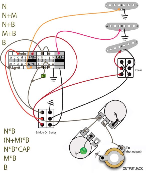 |
|


 and look where that's gotten us!