stewd
Rookie Solder Flinger

Posts: 12
Likes: 0
|
Post by stewd on Apr 24, 2011 20:06:16 GMT -5
Hi all, New to the forum and to guitar wiring in general so hope my question isn't too stupid  I'm planning a Les Paul build and was wondering if it's possible to wire a HH Les Paul with a 3-way switch AND a rotary switch? I'd like to achieve the following options at each position on the rotary: Position 1: standard LP pickup selection using the 3-way Position 2: (bypass 3-way) outer coils in series Position 3: (bypass 3-way) outer coils in parallel Position 4: (bypass 3-way) inner coils in series Position 5: (bypass 3-way) inner coils in parallel Position 6: (bypass 3-way) neck pickup coils in parallel Apart from position 1, they don't have to be in this order—these are just the options I'd like. Would be happy to go with a 5-way rotary and drop position 4 (inner in series) if that makes it any easier. I'd be looking for a stock LP 'look'—probably with master vol, master tone, rotary and a dummy pot. Would be great if I could do this without any other routing. Pickups will be Bill Lawrence L-90s. All thoughts greatly appreciated. StewD |
|
|
|
Post by newey on Apr 24, 2011 20:42:04 GMT -5
stewd-
Hello and Welcome!
What you want is certainly possible, provided the rotary switch has a sufficient number of poles. Not sure how many you'd need, but I'm thinking at least 4 will be needed, which would mean a 4P6T rotary.
There may already be a scheme around here that's close, we'll let others chime in with their suggestions.
If it were me, I'd keep the separate Vols and use a master tone, which can be done with a dual-gang pot - why waste the hole with a dummy pot?
Depending on how many poles are needed, you should be OK without further routing. Too many poles on a rotary gets to be pretty deep, unless you spring for the mini mil-spec ones which get pricey.
|
|
|
|
Post by JohnH on Apr 24, 2011 22:47:48 GMT -5
A noble intention stewd!
As newey says, certainly possible given enough switch poles.
I can see some practical issues to address:
On the face of it, it may need as many as 6 switch poles, being two for series/parallel, one for toggle bypass, one to control coils on the bridge, and two for the neck, where local parallel is wanted. Sometimes, with careful design, switch poles can be cleverly be made to achieve two functions, but that somewhat is dependent on luck and an alignment of planets.
The largest standard types of rotary switches have 4 poles with 6 positions, or other combinations adding up to 4x6= 24 lugs. So it may be that some less common switch is needed.
The next thing with an LP, is getting through the thickness of the topping, which is why long-shaft pots are usually needed. Having extra length in a rotary switch is therefore another limitation. Ive put standard 4-pole rotaries in an LP copy, but it had a less than normal body and topping thickness.
Maybe if a Les Paul grounding plate was used (some LP's have them, including my '91 Studio), the switch could be nutted off to that, with just the spindle extending through the body?
It might free up the options if a different control scheme were acceptable. Eg, a 3 position rotary to select full humbucker, inner coils and outer coils. Have the main toggle only bypassed in series modes, and have a push-pull for series/parallel. This would also give you single coil sounds too.
John
|
|
|
|
Post by newey on Apr 24, 2011 23:00:43 GMT -5
Ouch. My estimate of "at least 4" was rosy to say the least.
I can see being able to do it with 5 poles, assuming that the Bridge coil cuts could share a pole with the neck parallel- which I'm sort of visualizing but haven't actually drawn!
Yeah, or perhaps go with master V & T, and 2 rotaries could be used. Each one would have a bypass setting, so two 3P4T should do it. I believe Mouser has these switches available.
|
|
|
|
Post by newey on Apr 24, 2011 23:27:23 GMT -5
|
|
stewd
Rookie Solder Flinger
Posts: 12
Likes: 0
|
Post by stewd on Apr 25, 2011 2:35:33 GMT -5
Wow ... you guys are fast!  Thanks so much for your thoughts. Ok, so bearing in mind everything you've said, how do I go about making this happen? I can solder ok and have some idea about basic wiring schemes but don't know squat about rotaries! Can you point me somewhere I can get educated? ... unless one of you generous blokes are offering to work it all out for me?! It might free up the options if a different control scheme were acceptable. Eg, a 3 position rotary to select full humbucker, inner coils and outer coils. Have the main toggle only bypassed in series modes, and have a push-pull for series/parallel. This would also give you single coil sounds too. Yeah John, that'd probably be ok. I assume I'd need another push/pull for the neck coils in series? Besides the different sound options the two things I want to achieve with this project is the stock look and to be able to pass the guitar to anyone familiar with a Les Paul, leaving the rotary in position 1, and know that they can approach it like any regular LP. Thanks again ... keep the thoughts coming.  Stew |
|
|
|
Post by newey on Apr 25, 2011 5:37:47 GMT -5
Think of a rotary just like a lever switch that's been rolled up into a ball. The common, or "pole" connections are in the center, and, as the knob is turned, the commons connect to each outer lug in succession.
The best way to understand one is to have one in your hand and apply a multimeter to it to work out the logic.
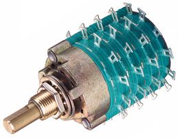
Any diagram or schematic using a lever or toggle-type switch can be easily converted to a rotary, so long as the rotary is "formatted" the same as the switch on the diagram one wants to utilize. So, a Superswitch is a 4P5T lever switch; any diagram using one could be implemented with a 4P5T rotary switch, if such could be found. The 6P6T pictured above could be used; there would be an extra unused position on the switch though (and 2 unused poles as well).
|
|
stewd
Rookie Solder Flinger
Posts: 12
Likes: 0
|
Post by stewd on Apr 25, 2011 8:28:32 GMT -5
Yeah, I might have to get a 4P5T (?) like this www.guitarelectronics.com/product/SWR51/5-Way-Rotary-Guitar-Pickup-Selector-Switch.html and play around with it. Maybe try something simpler like the standard PRS wiring first. For the life of me I can't get my head around it by looking at wiring diagrams! ... and I wouldn't have a problem paying $38 for that beast you posted earlier newey if I knew it was gonna do the job. Providing I was able to fit it in the control cavity!! Is there any way to get a short shaft pot to fit a LP? Am open to any other suggestions. Cheers, Stew |
|
|
|
Post by newey on Apr 25, 2011 10:12:41 GMT -5
This would involve countersinking from inside the cavity, so as to recess the pot from the inside. I've never done anything like that, and I'd be worried about leaving too little wood. A risky proposition at best, if someone else here has done that let's see what they have to say about the procedure.
|
|
|
|
Post by ashcatlt on Apr 25, 2011 11:31:25 GMT -5
The 4P5T you've linked is probably cheaper from mouser. They're made by Alpha (Taiwan) and they have several different configs. I've got the DP5T version in place of the toggle in the upper bout of my LP. Didn't have any trouble getting through the body thickness there. Haven't tried it in place of one of the pots, but it might just fit with out the ground plate. Important to note here also that these are solid 1/4" shafts. They won't fit in normal guitar knobs meant for split/knurled shafts without some modification. We've talked about that before, and there are a couple ways to get around it. Edit - Yep. They're a little cheaper at mouser. Not sure how shipping compares. If you click through to the catalog page it's kind of confusing, since the "number of poles" column should be labeled "poles per deck". They have a 4P6T and a 6P4T. Like John says max of 24 altogether. |
|
|
|
Post by sumgai on Apr 25, 2011 13:09:33 GMT -5
Just to throw some oil on the fire..... It's not the length of the shaft that's important to consider here, it's the length of the bushing. The shaft may extend from the end of the bushing by the same amount (after all, how much shaft to you need to mount a knob), but if the bushing is too short, some alternative method of mounting it will have to be devised. A metal plate is worthy of consideration, whereas recessing the hole (hogging out more wood) is not - if the remaining (thin!) layer of wood was strong to hold the pot/switch/other control over a period of time, the manufacturer would have done this in the first place, and not spent the extra coin on the long-bushing controls. The project can be done, but it's not a 'quickie' - not if it's gonna be both usable and long-lasting.  Oh, and stewd - Hi, and  to the NutzHouse! sumgai Note to John: How come I don't smell any blend pots in this picture?  Dummy pot my sweet derriere!     |
|
|
|
Post by JohnH on Apr 25, 2011 16:22:54 GMT -5
Yeah, bushing! That's the bit that has to be long on controls for an LP. Then they call the resulting item, a ’long-shaft’ pot! Proper LP’s are made with a flat slab of mahogany (out of 2 or 3 pieces), then a panel of maple on top. The maple starts life, I think, at about ½” or 5/8” thick, and is shaped towards the edges to give the top carve, so its maybe ¼”or 5/16”at the edge. Customs and Standards are a bit thicker than Classics and Studios. The switch routing is all put into the mahogany, and the Maple cap is just drilled. So the depth that the pots have to get through is that of the Maple at any given place. Therefore, the neck pots, being nearer the centreline have to go through more wood than the bridge pots. Also, relating to Ash’s experience, the maple is getting thinner at the toggle switch position. My LP rotary design also used those alpha pots, purchased from Mouser. They are good solid items and good value too and have been very reliable. The guitar that they went into had just ¼”or 6mm of top wood, and I just got the nuts on. Any more that that and I’d have needed some woodwork. On the face of these switches, where they contact the wood, there are two bolt heads which project about 2mm. If just two small holes 5mm diameter x 2mm deep were made in the back of the wood where these are, the switch could settle down further and a bit more bushing could be pushed through. So on mine, the total bushing length available is about 11mm. Curiously, the data sheet at mouser, currently linked to these alpha switches is this: www.taiwanalpha.com/english/p_e_147.htm...which shows a knurled shaft switch, with only 6mm bushing length, even though the link to it come from a round shaft listing. A bit puzzling, but if such rotaries are wanted, then I suggest the first thing to do is to get some accurate values for the top thickness at each position. BTW This is the one that I did. Slightly changed from the design drawn, it currently has a rotary in place of each tone pot that selects on each pickup: series, parallel, one coil, other coil(reverse phase) and series out of phase. It uses 4P5T rotaries. If I built it again, Id lose the last position and then I could have just 3P4T single layer rotaries. It now has a master volume and tone. The overall series/parallel wiring is on a toggle, which could also be a push/pull, overriding the main toggle in series mode. LP Maxcheers John |
|
stewd
Rookie Solder Flinger
Posts: 12
Likes: 0
|
Post by stewd on Apr 25, 2011 18:09:29 GMT -5
Ok, You're right newey ... don't think I wanna go there! Thanks for the mouser link ashcatlt. I also found this in their catalogue: au.mouser.com/ProductDetail/Electroswitch/D9G-499/?qs=sGAEpiMZZMvNbjZ2WlReYqOqgxm428ccIHv2GiP0w4U%3dWhat do you guys make of that? The bushing is still short but could maybe be mounted to a metal plate as sumgai suggested. The shaft is LONG but maybe could be cut down to fit?? So I'm guessing this is a 3 deck pot? Once again, would this even fit in a LP control cavity? I had seen your LP Max design John. It was what was hurting my brain last night when I was trying to work out how rotaries work It's a good alternative ... with two 3P4T single layer rotaries I could have everything I wanted and still retain the look. To be honest I was actually trying to avoid the single coil positions so that everything would be hum cancelling. I've got a strat if I want single coils. I'd still be interested to try and make this happen according to my original idea. But seeing as how I don't really know what I'm doing I will gladly default to what you 'Nuts' (and I mean that in the most endearing way) think is the best solution to meet my needs. ... and finally, I realise it's probably bordering on blasphemy to suggest a 'dummy pot' (sorry sumgai) I have some ideas of what it could be used for (if available) but I want to try to get the hard part worked out first. Thanks again folks for your help. Please keep the thoughts coming. Stew |
|
|
|
Post by newey on Apr 25, 2011 21:56:55 GMT -5
stewd-
The one you linked to from Mouser is a 24-position rotary- a few more than you were looking for!
It is also 2 5/16" wide- compare that to the width of a standard-sized pot like you probably have in there now, which is probably 24mm across, or just a hair under an inch. This thing's more than twice as wide. . .
And it still has a 3/8" bushing; while the shaft is made to be cut to the length needed, the bushing is the problem.
As you hunt for the appropriate parts, bear in mind that electronics suppliers such as Mouser are usually cheaper than guitar parts suppliers, but you need to double check that each part is what you really want/need.
Guitar suppliers only stock items that are usually used for guitar wiring; Mouser stocks many different types of switches, and not all will be suitable for guitar use in terms of shaft diameter, size, etc.
When searching Mouser, always click through the link to the manufacturer's product data sheet, that has all the info you'll need on dimensions. Double and triple check that each part is exactly what you want before ordering, 'cause returns are a PITA.
|
|
|
|
Post by JohnH on Apr 26, 2011 0:29:32 GMT -5
... keep the thoughts coming. Stew How about another type of idea? - based on your comment that you have a Strat and dont want single coil settings. I do not have a scheme for the following, but it is within range of something that might possibly maybe work. Get thyself a set of ‘Jimmy Page mod’ long-shaft push-pull pots, but instead of wiring them according to one of the many JP versions, have them do this instead; 2 volume and two tone pots, with the four push/pull switches. S1 ‘cross switch’ – when you pull it, swaps over the links that go between the north and south coils of each pickup. So when selecting what is usually Bridge humbucker, it is instead the Bridge south coil and Neck north coil, which could be arranged to be the two inner coils. What was the neck humbucker, similarly is now the two outer coils. S2 and S3, series/parallel for each pickup, and if S1 is pulled, you get the same series or parallel for inner and outer coil combos (thats the bit I’m not sure of). All combos hum cancelling, nothing too Stratish at all. So far, the main toggle keeps working as normal. S4 – overall series/parallel, over-riding the main toggle. So with all knobs in, it is completely as per a standard LP, and as you pull knobs, all the other sounds are all hum-cancelling. You get all the sounds you wanted and a few more. It all fits easily in an LP. Any good? John |
|
stewd
Rookie Solder Flinger
Posts: 12
Likes: 0
|
Post by stewd on Apr 26, 2011 2:00:27 GMT -5
... guess not then ... I'll work it out eventually newey ... I'm not the sharpest tool in the shed when it comes to this stuff [edited to add quote for context]
|
|
stewd
Rookie Solder Flinger
Posts: 12
Likes: 0
|
Post by stewd on Apr 26, 2011 2:21:30 GMT -5
S1 ‘cross switch’ – when you pull it, swaps over the links that go between the north and south coils of each pickup. So when selecting what is usually Bridge humbucker, it is instead the Bridge south coil and Neck north coil, which could be arranged to be the two inner coils. What was the neck humbucker, similarly is now the two outer coils. So what happens to the middle position on the 3-way when S1 is pulled? Just to make sure I'm following, S2 pulled would give me the two coils of say the neck pickup in parallel and S3 toggles serial/parallel for the two coils of the bridge pickup? Ah, ok ... so that answers my previous question—S1 pulled in middle position of 3-way is still both pickups in parallel ... yes? What ... are you kidding? Sounds VERY good |
|
|
|
Post by JohnH on Apr 26, 2011 6:27:54 GMT -5
Ok, well in that case, I thought I'd better sketch it out to see if it could work. The one part that did not seem to function properly is the overall series/parallel switch, which I think will get tangled up when the crossover switch S1 is pulled. Actually, all the sounds that you wanted can be had with just the other three push/pull switches. Here is a schematic sketch: Cross-switched LPSo, each pickup has its own series/parallel switch S2 and S3, and the S1 switch changes the selections from B and N to Inner and Outer. You would have to consider whether the B position should become the inner or the outer pair. The middle positions of the main toggle (now S4) would add all together. I suspect that, with S2 and S3 the same, then B+N, will sound the same as Inner+Outer, since the same coils are involved in a similar overall electrical arrangement. Also, if you have two identical humbuckers, ie say both screw coils are south polarity, you will need to point them the same way, eg screw coils nearest to neck, so inner and outer pairs each have a north and a south. cheers John |
|
stewd
Rookie Solder Flinger
Posts: 12
Likes: 0
|
Post by stewd on Apr 26, 2011 18:04:48 GMT -5
Wow ... that's great John! Will have to give it a try and see how it suits ... and see how well I can follow the schematic and put it all together One other, related question: What's a good source for parts like the long shaft push/pulls for us Aussies? Most of the sites I have been looking at are OS. Thanks again ... Stew |
|
|
|
Post by newey on Apr 26, 2011 18:29:31 GMT -5
|
|
|
|
Post by JohnH on Apr 26, 2011 23:09:47 GMT -5
Stew - I hadn't realised you are also down here!. I trust you had a nice 5-day weekend.
Neweys link is the nearest I know of, but I have not tried them nor bought long shaft push/pulls myself. I suggest that 4real may know a good source (hes on Philllip island, and built a push/pulled LP recently. Other than that, I'd suggest comparing what our over-powered $ can now buy in the US, with shipping, as compared to buying from NZ. For general electronic parts, not guitar-specific, I go to Jaycar locally.
John
|
|
stewd
Rookie Solder Flinger
Posts: 12
Likes: 0
|
Post by stewd on Apr 27, 2011 3:39:02 GMT -5
Stew - I hadn't realised you are also down here!. I trust you had a nice 5-day weekend. I'm only working four day weeks at the moment, so not only did I just have a five day weekend, I'm currently half way through my two day week before having a four day weekend (Labour Day on Monday)! It's a tough life. Thanks Newey, they look good and shipping is only $10—better than what I've seen from US sites. John, I'll probably have to read over your schematic a few times to get my head around it and make sure it makes sense to me—expect more questions down the track! Cheers, Stew |
|
stewd
Rookie Solder Flinger
Posts: 12
Likes: 0
|
Post by stewd on Jul 30, 2011 4:30:48 GMT -5
Ok ... resurrecting this post from the dead! For a number of reasons this project didn't get off the ground earlier in the year. I'm now going to install new pickups and this wiring scheme in my old Ibanez Deluxe 59'er Les Paul. It already has a mini toggle hole so I'll use push/pulls on the vols for the pickup series/parallel and the mini toggle for the coil swap. I've actually ordered the parts and the pickups so this is really gonna happen this time! I was hoping you guys could have a look at the attached diagram to see if I've interpreted JohnH's scheme properly and made the correct adjustment for the mini toggle. Like I said in an earlier post, my soldering is ok but I'm pretty new to guitar wiring so I just wanted to be sure that I've got it all straight in my head where all the connections go.  Thanks! |
|
|
|
Post by newey on Jul 30, 2011 10:31:39 GMT -5
stewd-
I believe you've got it!
I hadn't really looked at this scheme of John's in detail before, but I think it's a pretty cool idea. and if it works out to stewd's liking, I think it belongs in the schematics section. I haven't seen this type of "cross-switching" done before, certainly not with the HB internal series/parallel switching as well.
One thought that I'll throw out (and I don't see any way around this given the series/parallel switching here) is that, when the cross switch is thrown, one coil from the bridge pickup is on the neck's V and T controls, and vice versa. If one pickup is "hotter" sounding than the other, this might be a bit disconcerting in practice, since any "pre-set" of the bridge and neck pups to compensate for the imbalance then goes by the wayside once you throw the cross-switch.
Probably not a big deal, but just something to consider.
|
|
stewd
Rookie Solder Flinger
Posts: 12
Likes: 0
|
Post by stewd on Jul 30, 2011 15:59:19 GMT -5
Thanks for looking it over newey! The pickups are being custom made by an Aussie guy named Mick Brierley www.brierleyguitarpickups.com.auWhen I told Mick about the wiring he said he'd use his standard hot bridge wind and custom wind the neck to match, both in humbucker mode and when split. I think they're goin to sound great! I'm more a home studio guy than a live player anyway, so I'm not too worried about how easy it is to switch from one mode to another ... it's more about having some extra options. Originally my thought was to have inner coils on the neck pickup controls and outer coils on the bridge, but the way my diagram is it goes the other way. Doesn't really matter as long as I remember which is which ... and I agree, it's a pretty cool wiring scheme. Like I said I'm pretty new to this stuff but I learned a lot by creating that diagram over the last couple of days. I really started to see how it was all working. Beautiful in it's simplicity. Nice work John! |
|
|
|
Post by JohnH on Jul 30, 2011 16:09:20 GMT -5
I agree, all fine - and that is a very nice diagram indeed.
It looks like MB is using standard Seymour Duncan wiring colours for his pickups, so it will work with SD pups too. The scheme depends on both pickups having the same standard convention for North and South, screw and slug coil, as you have drawn them. It might be a good idea to send him the diagram just to be sure.
One small watchit: mini-toggles are made such that when the lever is flicked say, 'up', the centre lugs are connected to the outer lugs on the 'down' side.
Where did you get the pots?
This should be good!
cheers
John
|
|
stewd
Rookie Solder Flinger
Posts: 12
Likes: 0
|
Post by stewd on Jul 30, 2011 18:01:14 GMT -5
I agree, all fine - and that is a very nice diagram indeed. It looks like MB is using standard Seymour Duncan wiring colours for his pickups, so it will work with SD pups too. The scheme depends on both pickups having the same standard convention for North and South, screw and slug coil, as you have drawn them. It might be a good idea to send him the diagram just to be sure. One small watchit: mini-toggles are made such that when the lever is flicked say, 'up', the centre lugs are connected to the outer lugs on the 'down' side. Where did you get the pots? This should be good! cheers John Thanks John. I've already confirmed with Mick re his pickups. They're the same as SD and the same convention is used for North/South. Thanks for the advice about the toggle ... I probably wouldn't have caught that, until after it was in place! The pots are coming from www.guitarparts.co.nzIn the end I only need regular length pots because the lam top on the Ibanez is super thin. The standard length pots that are currently in there have extra washers on them so they don't stick up too much I was thinking linear pots for tone ... are they preferred over audio taper? |
|
|
|
Post by JohnH on Jul 30, 2011 18:15:44 GMT -5
If you already have bought the pots, then linear is fine if that's what you have, but I think audio is better for tone pots. It makes no difference to the overall range, but with linear, most of the tone-change action is between 0 and 2, wheras with audio taper, it is more stretched out, about 0 to 6.
Also, audio for volume pots if you are using the 1nF and 150k treble bleed bits as shown. The 150k tends to flatten out the pot taper (in a good way, on an audio pot)
John
|
|
stewd
Rookie Solder Flinger
Posts: 12
Likes: 0
|
Post by stewd on Jul 30, 2011 19:17:33 GMT -5
Fortunately I thought I'd wait until you guys had confirmed my diagram was ok before I placed my order. So I'll go for audio taper all round then. Thanks again folks ... will let you know when the beast comes together |
|


 Dummy pot my sweet derriere!


