Gman777
Rookie Solder Flinger
 JN.3:16
Posts: 15 
Likes: 0
|
Post by Gman777 on Jul 22, 2011 7:32:52 GMT -5
Thanks newey, john, for setting me straight on this, sorry for the confusion, i just thought i could keep the pick guard as stock as possible, but 1 switch i think would be worth it. also. yes, lets put the tone on the bridge... so the 2nd schematic is that the one i should use? plus a toggle am i correct? i would like to see how i make the connections , i need a revised schematic if i can be a pain... i also forgot. the coil split, you mentioned using the south for less hum, is that still possible.
thanks again
Gman
|
|
|
|
Post by newey on Jul 22, 2011 12:21:30 GMT -5
No, don't use the second diagram* if you want to use the toggle switch. The second diagram was based on you wanting to keep the pickguard stock, and involved losing one of the std. Strat positions.
With the toggle, you'll keep the regular wiring to the 5-way which you probably already have.
I'll try to draw up a revised diagram for you this weekend if you can wait another day or so. I'll do this complete, with the tone controls as you want them (neck and bridge, right?) and showing all the push/pulls, etc.
And yes, we can deal with the hum-canceling aspects as well.
* Notice that I did not say "schematic", these are wiring diagrams we have been discussing, not schematics.
I would be happy to do a schematic if you want one, they're much easier to do than a wiring diagram- but I believe you said that you were not able to decipher a schematic, so I'll stick to the wiring diagrams as previously done.
|
|
|
|
Post by newey on Jul 24, 2011 10:40:03 GMT -5
OK, gman, here you go:  A few notes on this: First, while I'm reasonably sure this is good to go, let's let someone else give it the OK before you start wiring. Two heads are better . . . Second, on this diagram, wires that cross each other are NOT connected to each other, there was just no other way to draw the diagram. Also, I have shown this with separate capacitors for the neck and bridge tone controls. This is different than a std. Strat, where the two tones share the same capacitor. Doing it this way allows the use of a different value capacitor for the bridge tone and the neck tone; I feel this is desirable since you want the second tone on the bridge instead of the middle. Capacitor value is a matter of taste; since you have HB and SC options, some compromises need to be made. I would go with .047µf for the bridge and .022µf for the neck, but that's just one schlub's opinion. If you want to save the extra capacitor, you can just use the one and wire it as a shared cap between the 2 tone controls, as per std. Fender practices. I have not shown the bare shield wires from the pickups, these go to ground. I also have not shown a bridge/string ground, which also goes to ground. Push/Pull pots ordinarily have a little tab on the end of the switch portion to ground the switch chassis. I show these tabs and use them for grounding various things. The middle P/P on the diagram (which is the neck tone pot) is shown as being the grounding point for all the other components. This is what is called a "Star Ground"- a single point where all the grounds meet. You can use any point that's convenient for grounding. If you decide to use the tab on one of the P/P pots, as I have shown, you will quickly find that you can't solder all those wires to the little tab, there's not enough room. Best thing to do is to use a grounding buss. This could be pretty much any piece of conductive metal that you can solder a bunch of wires onto- you can use a large ring connector, a bent paperclip, whatever. Solder all your grounds to the buss, and connect the buss to the tab on the P/P pot with a bit of wire. Wrap the "grounding buss" with electrical tape to insulate it so it doesn't contact any of the hot wires once you install the pickguard. Another way to do this is to mount a screw or a post of some sort into the side of the cavity and use that as the grounding point. That may be more secure than a "floating" grounding point. I have used all of these methods with success in the past. Just make sure everything is solidly connected together at the grounding point. The "Neck On" switch is shown as a single pole, double throw (SPDT) toggle switch, "On-On" type. As I noted earlier, you could accomplish this without the switch by using the neck tone pot to do the switching- see the link that I posted to ChrisK's "Free Neck On" switch. This would keep your stock look, but some folks prefer the positive "click" of a switch (less "fiddle-ly" when playing live) to having to turn a pot to get the neck on. I have also wired the neck pickup "inside out" so that the South coil is selected in the coil-cut position; the bridge and middle pickups cut to the North coil in SC mode. This makes N+B hum-cancelling when in SC mode, and also N+M. N+M+B will be partially hum-cancelling (when set to SSS). B+M will not be hum-cancelling. I did it this way as I figured you would want the N+B to be hum-cancelling; if you'd rather have the B+M quieter than N+M, you can wire the bridge inside out instead of the neck. If you want it to have the std. Strat hum-cancelling in positions 2 and 4, then the middle pup would get the reverse treatment- but then B+N would not be hum-cancelling. Of course, all of this matters only when you are in SC mode, all the HB positions should of course be hum-cancelling. The P/Ps are wired such that SC mode is activated when the pot shaft is pulled up, HB with it down. If you want it the other way around, then the opposite lug (upper one as shown) gets grounded instead of the lower one. Please feel free to ask any questions before you start. |
|
|
|
Post by cynical1 on Jul 24, 2011 11:58:18 GMT -5
...Best thing to do is to use a grounding buss. 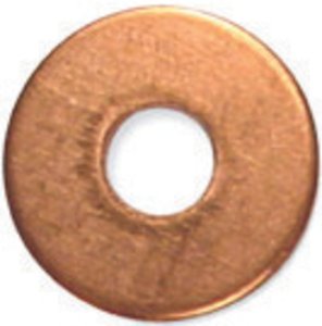 10mm x 1/8" BSPP Copper Washer - Wholesale Price: $0.2825 10mm x 1/8" BSPP Copper Washer - Wholesale Price: $0.2825I have a bag of these things. Just rub the top of the washer on a course file for a few seconds and you can solder anything to it. I just use a 3/8" long brass screw to fasten the washer to the shielding once all the ground connections are soldered. Granted, this creates a material mis-match between the brass and the copper, but I'll be long dead before it's an issue. I can't speak to the drawing, aside for the fact that I wire my neck\bridge on switches to the Common on the 5-way, but that's just me. Happy Trails Cynical One |
|
|
|
Post by JohnH on Jul 24, 2011 19:06:59 GMT -5
newey - I had a quick look this morning, but cant see the diagram right now where I am. Could you check the wire colours on the neck pickup. With SD colours, and reversing the coils to help humcancelling such that green/black are the two joined, then the red wire becomes the required hot connection for humcancelling in-phase.
J
|
|
|
|
Post by newey on Jul 24, 2011 19:23:39 GMT -5
Thanks, John, right you are, I had it backwards!
I'll make the change.
|
|
|
|
Post by newey on Jul 24, 2011 19:29:02 GMT -5
OK, correction made.  |
|
Gman777
Rookie Solder Flinger
JN.3:16
Posts: 15
Likes: 0
|
Post by Gman777 on Jul 25, 2011 7:48:38 GMT -5
thanks Newey: and everyone who put in on this build. i copied all the schematics on the last up date, and have the print out of the notes to it. i am really grateful for all the time you guys spent on setting me straight, and helping me get to the reality of it. if i have any problems. i will let you know. but everything is crystal clear for now. again, thanks for everything.
Newey: i almost for got. the strat i am building is left handed. as i look at the 5 way switch that is in the diagram, i will have to reverse the wiring connection's won't i ?...... i know i wired it once before and the neck position of the switch ended in the bridge position. i just don't mess this up . thanks: Gman
Gman
|
|
|
|
Post by newey on Jul 25, 2011 12:05:45 GMT -5
Gman-
Yes, for lefty you'll have to mirror-image the switch wiring. Best thing to do is to check your switch with a meter before wiring it and mark the commons, then check the various positions to be sure they're right.
You will also have to swap the outer lugs of the pots from what I have shown. These are shown as if looking from the back; you'l just reverse the right an dleft lugs for lefty operation (so that turning the knob CCW turns it "Up").
|
|
Gman777
Rookie Solder Flinger
JN.3:16
Posts: 15
Likes: 0
|
Post by Gman777 on Jul 25, 2011 14:27:30 GMT -5
Will do... i shouldn't have any problem.. thanks for your help newey... may you get maverick beach type waves.. coming from a so cal guy for 40 years.... surf's UP dude....
Gman
|
|
|
|
Post by ashcatlt on Jul 25, 2011 19:27:02 GMT -5
I can't speak to the drawing, aside for the fact that I wire my neck\bridge on switches to the Common on the 5-way, but that's just me. Ah, it's all going the same place! That could be an SPST, though. |
|
|
|
Post by cynical1 on Jul 25, 2011 21:58:30 GMT -5
Ah, it's all going the same place! No argument there. HTC1 |
|