|
|
Post by ashcatlt on Jun 11, 2012 13:14:36 GMT -5
Some opamps require an external "compensation" cap. While I cant explain how or why, the value of this cap does in fact directly influence the slew rate of the opamp.
It was something of a fad for a while to add a "dying battery" simulator to damn near everything. AFAIK, lower voltage is one thing by itself, but a dying battery also starts to exhibit more resistance, which causes the voltage to sag even further under high current demands. I guess something like the squishiness of a tube rectifier, or something...
I've been working on a circuit which uses only opamp clipping, and runs off of a 3V supply. This is partly to get more distortion with less gain, and partly to limit the output volume and avoid having to attenuate later. A TL07x opamp will only get to within a volt or so of each rail, so the output from a 9V supply will "only" be about 7V peak-to-peak. That much voltage, though, makes my Vox AC4 fall completely apart. It's not a "wow that's nasty and cool" type of thing, but a "the amp doesn't know what to do and just gives up" type thing.
|
|
|
|
Post by reTrEaD on Jun 11, 2012 15:34:13 GMT -5
It was something of a fad for a while to add a "dying battery" simulator to damn near everything. AFAIK, lower voltage is one thing by itself, but a dying battery also starts to exhibit more resistance, which causes the voltage to sag even further under high current demands. I guess something like the squishiness of a tube rectifier, or something... Absolutely. Although the terms squish and fizz are generally associated with preamp distortion but sag and crunch are generally associated with power amp distortion. A battery on its last legs will produce a lower voltage even under light loads, but the voltage drops severely as the current demands increase. Most of the "dying battery simulators" just add series resistance. This does a very good job of mimicking the internal resistance of a dying battery. RG Keene has this theory about using multiple stages, each just barely clipping the signal, so that each stage stays pretty much in that "knee" region. I don't know that he's ever really come up with "finished product" though. Guitar signals are wildly dymanic and pretty unpredictable. Even if you built such a thing for one specific guitar/pickup/player, it's tough to get it to react the same across the neck and up the fretboard. It's an interesting idea, but difficult to implement. The more stages you use, the better it can tolerate dynamics. In the linear region of a device's conduction curve, gain is fairly constant. But when we get close to saturation or cutoff, the gain decreases. So there is an inherent "compression" that occurs when the signal excursions are large enough to just enter these regions. Careful alignment is the key to getting the most out of this concept. Attenuation is trimmed between stages. If each stage is identical and there is no attenuation between stages, the latest stage would be where all the distortion occurs. If the attenuation after each stage is exactly equal to the gain (in the linear region), the first stage would be where the heaviest distortion occurs. It's best to have the last stage enter distortion just slightly before the stage that precedes it in the chain. Once trimmed, the only adjustments that need to be made on a regular basis are the attenuator just before the chain and the one at the very end. |
|
|
|
Post by geo on Apr 27, 2023 23:53:22 GMT -5
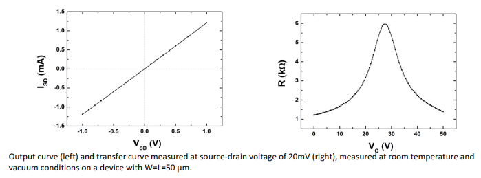
Sorry for necroing this super old thread, but can anyone tell me what you might make of interest with this?  |
|