|
|
Post by newey on Jan 25, 2012 7:11:06 GMT -5
Yes, in position 1 each #1 lug is connected to its respective common lug. IIRC, in asmith's diagram, the neck is not "on" in position one, because both ends of the coils(s) are shorted together.
All P/P pots are the same, they are all DPDT On/On switches.
|
|
|
|
Post by reTrEaD on Jan 25, 2012 10:04:09 GMT -5
The green and white wires are indeed the screw pole (south) ones  (source: I've confirmed it in the results of previous instalations I did with these dimarzio pickups I have. Don't know how dimarzio could put the wrong information on manual!They didn't. The manual was for a specific pickup (Bluesbucker) that is wired differently from most other Dimarzio pickups. |
|
|
|
Post by asmith on Jan 25, 2012 14:36:16 GMT -5
Yes ddsebrian, I was too quick off the mark with a conclusion. I drew that original diagram as though the slug coils were screw coils and vice versa. If you use the wiring colours for the superswitch as in that diagram, then your guitar will be fine. Notwithstanding the Screwdriver and Phase tests - always useful, and I may have further missed something along the way. And I do all my diagrams on MSPaint as well. Use the middle setting of the line tool for my wire widths, and the thickest circular brush for the connections. I have a PNG file of commonly used components to cut, paste, chop and shop, which saves repetitive drawing. Let me know if you'd like it. Right, I'm done. |
|
ddsebrian
Rookie Solder Flinger

Posts: 18
Likes: 0
|
Post by ddsebrian on Jan 28, 2012 6:51:26 GMT -5
reTrEaD: sorry for the ignorant statement about dimarzio. thought it was from a universal manual of all their pickups.
asmith: thank you for your patience and solutions. i will study further the schemes and wiring basics to stop bothering the forum with basis questions. Then I'll double-check and solder it. If any future problems show up is ok for me to ask? Don't wanna bother you.
If you could send me the PNG file of components it would help me immensely for my study diagrams. ddsebrian@yahoo.com.br
Thank you guys
|
|
|
|
Post by newey on Jan 28, 2012 7:51:59 GMT -5
Of course, ask away, that's why we're here. If no one asked questions about guitar wiring, this forum wouldn't exist.
There are no stupid questions, so long as you don't already know the answer.
Stupid answers? We've got plenty of those, but hopefully we get it right most of the time.
|
|
ddsebrian
Rookie Solder Flinger
Posts: 18
Likes: 0
|
Post by ddsebrian on Feb 3, 2012 17:47:26 GMT -5
I've studied a lot and came with this scheme (just like aasmith's one, but now with the right colors and now I do understand it): 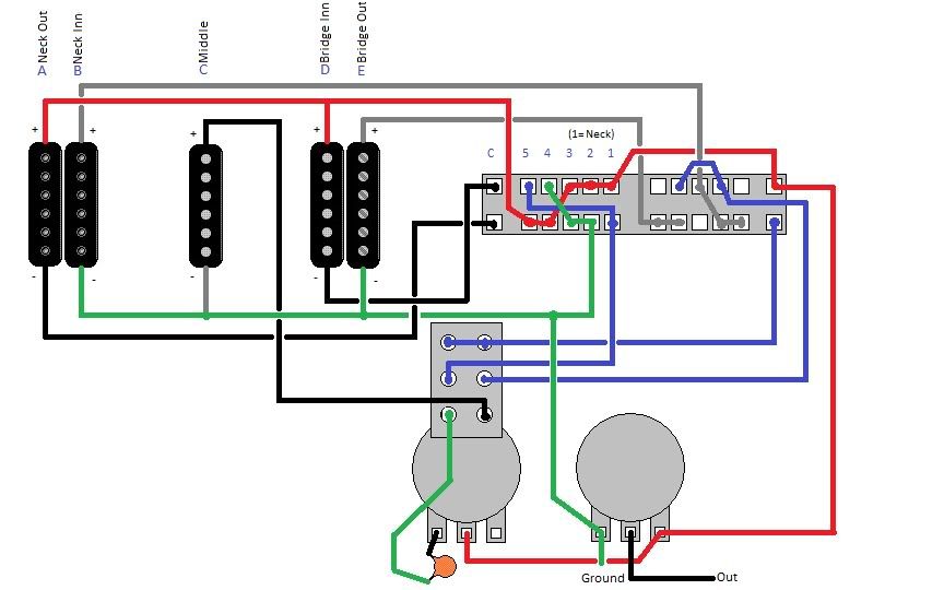 [To represent polarity in the right way, probably the middle pickup should be inverted in the graphic. Anyway, i'm sure about the polarity. we don't have to take this in account here.] What we wish to have: 1. AxB 2. A+B 3. B+D 4. D+E 5. DxE Push/Pull up: 1. A 2. A+C 3. B+D 4. C+D 5. D My analysis and questions about this wiring: (Leg: Neck Red = NR+, Neck Black = NB-, Neck Green = NG-, Neck White NW+, etc) Our Red+ is the HOT. Is it ok for it to be connected like that? Push Pull down. In pos 1, that should be 'neck on', we have 'on': NW+, NB-, NR+, BB-, BR+. NG- and BG- grounded. Right? So, what happens when we have the BR+ and BR- connected, BG- grounded and BW+ 'floating'? This is an error or the bridge would be off? This is the main question, the other ones are derivate from this. Thank you all one more time! |
|
|
|
Post by newey on Feb 3, 2012 20:34:59 GMT -5
I'm not following what you mean here. Position 1 looks fine to me. It's position 3 where you have issues.
Position 3 is supposed to be B + D regardless of the position of the P/P switch.
In position 3 , Coil D has its red wire permanently connected to the output. The black wire is connected to the upper left-hand common lug, where at position 3 it is connected to the red wire, thus shorting the output. So, you won't get coil D at all in position 3.
You will, however, get coil A at position 3. Coil A's red wire connects to the output; its black wire is grounded via the lower left hand common lug, which is grounded at position 3 via the green wire.
So, at #3, you'll have A + B. same as at position 2.
|
|
ddsebrian
Rookie Solder Flinger
Posts: 18
Likes: 0
|
Post by ddsebrian on Feb 5, 2012 6:53:56 GMT -5
You're right newey...
I thought about it but I couldn't solve this problem...
Anyone has a solution for what he stated about pos.3?
Or other plausible alternative for this wiring?
What I was saying about pos.1 is that the Neck wires are connected right, but all wires from bridge except White are also connected. When this happens what result do we have?
I mean, not connecting White would be enough for having no output from a pickup, even if the hot wire is connected (Red)?
Another question:
For connecting the pickup in series (DiMarzio colors talking, as in the last diagram) we have to ground Green- ; Black- and White+ go together ; and Red+ is the Hot.
In this Scheme Red+ (not White+) is connecting directly to Black-.
Understand what I'm saying?
Is this another problem?
These are some questions I couldn't solve by my own after researching and studying...
Thanks!
|
|
|
|
Post by newey on Feb 5, 2012 8:51:03 GMT -5
Since, in this scheme, the coils of the bridge are split in certain positions, let's consider the coils of the bridge pickup individually in position 1. Neither should be making a signal in that position, regardless of the P/P position.
Coil E has its green wire grounded, but the white wire is disconnected, so we get no signal from coil E at position 1.
Coil D has its red wire connected to hot. The black wire connects to the upper left of the 5-way; at position 1, it is connected back to the red wire, thus shorting that coil out. We get no output from a coil when both ends are connected together.
With the red wire permanently connected to the "hot", we don't want to simply disconnect the ground wire to disconnect a pickup, this results in the coil "hanging from the hot", which can cause noise. It may be OK to do this but we strive to avoid hanging coils whenever possible.
|
|
ddsebrian
Rookie Solder Flinger
Posts: 18
Likes: 0
|
Post by ddsebrian on Feb 5, 2012 9:07:27 GMT -5
I understood newey.
Then I think this wiring would not work properly or 'smoothly' with just one superswitch and one push-pull.
|
|
ddsebrian
Rookie Solder Flinger
Posts: 18
Likes: 0
|
Post by ddsebrian on Feb 5, 2012 15:22:17 GMT -5
I finally forgout about the middle pickup and came to this: 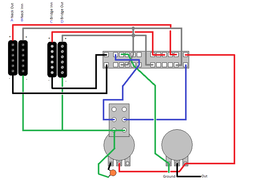 Hope this will give me: 1. AxB 2. A+B 3. B+C 4. C+D 5. CxD Push/Pull up: 1. A 2. A+B 3. B+C 4. C+D 5. D I wish to ask one more thing I couldn't figure out by myself. Maybe it's a dumb question, but better a dumb question solved than unsolved: 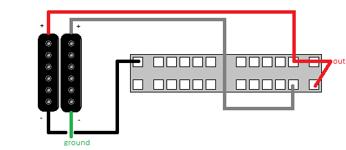 This would give me Series connection even if the Black- wire is not 'directly' connected with White+? I mean, in dimarzio 'official' diagrams always the White+ in connected in the same pole that Black- is. |
|
|
|
Post by newey on Feb 5, 2012 17:09:25 GMT -5
No. Both + wires (Red and White) are connected to output (at position 1). Green is grounded, so that coil will operate. The black wire isn't connected to anything, so that coil won't operate.
If you grounded the black wire, you'd have the two pickups operating in parallel, not series.
Using the DM colors, you can wire a HB with the white and black making the series connection (this is the way DiMarzio shows it.) Or, you can wire it with the red and green wires together. Either way, the two coils will be in phase.
Wiring red to white, however, or green to black, put the two coils out of phase with each other.
|
|
|
|
Post by reTrEaD on Feb 5, 2012 18:11:43 GMT -5
Hope this will give me: 1. AxB 2. A+B 3. B+C 4. C+D 5. CxD Push/Pull up: 1. A 2. A+B 3. B+C 4. C+D 5. D You'll be unable to get the parallel combinations, because you have only one pole of the superswitch (upper right) connected to the "hot" output. This means you can only connect one coil at a time to the hot. The two poles on the left are well used, allowing the (-) of A and C to be connected as a series link or to ground, as needed. The pole on the lower right is poorly used. I'd repurpose that as a second connection to the "hot". Rewiring the push-pull will also be necessary. One pole of the PP will route the connection from the rightmost throw of the lower left section of the superswitch, to ground when pulled and to B(+) when the PP is pushed. The other pole of the PP will route the connection from the leftmost throw of the upper left section of the superswitch, to ground when pulled and to D(+) when the PP is pushed. |
|
|
|
Post by reTrEaD on Feb 5, 2012 20:35:12 GMT -5
I gave this some additional thought. Hope this will give me: 1. AxB 2. A+B 3. B+C 4. C+D 5. CxD Push/Pull up: 1. A 2. A+B 3. B+C 4. C+D 5. D This gets you a total of 7 different combinations. The only thing that changes are the series combinations on 1 and 5. If you built this basic scheme around a series/parallel switch for the PP, you could get 10 different combinations. Perhaps something like this. Push/Pull down: 1. A + (CxD) 2. A+B 3. B+C 4. C+D 5. D + (AxB) Push/Pull up: 1. A 2. AxB 3. BxC 4. CxD 5. D Does that interest you? |
|
ddsebrian
Rookie Solder Flinger
Posts: 18
Likes: 0
|
Post by ddsebrian on Feb 6, 2012 12:30:14 GMT -5
reTrEaD i really do prefer the wiring with those 7 combs I said. It would have exactly the combinations I'd use most and with easy access. I did this ugly diagram to understand what u said. See if this is correct: 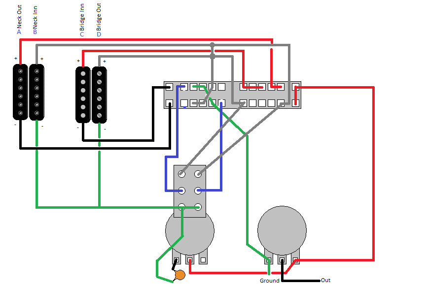 I guess that the PP connections are inverted... upside-down. Exchange ground with white wires. |
|
|
|
Post by reTrEaD on Feb 6, 2012 13:05:09 GMT -5
reTrEaD i really do prefer the wiring with those 7 combs I said. It would have exactly the combinations I'd use most and with easy access. Fair enough. I did this ugly diagram to understand what u said. See if this is correct: I'll look it over carefully and post again when I've finished. |
|
|
|
Post by reTrEaD on Feb 6, 2012 22:39:01 GMT -5
I guess that the PP connections are inverted... upside-down. Exchange ground with white wires. The PP connections were actually correct. Since this is the rear view, the PPs are pulled toward the bottom of the page. But the pots were backward, you made 2 errors on the lower right portion of the superswitch, had white wires joined together where they shouldn't be joined, and the instructions I gave you resulted in C rather than D for the single in position 5. It seemed easier to just redraw rather than describe how to fix it. 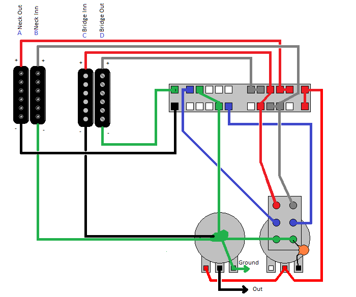  Normal: 1. AxB 2. A+B 3. B+C 4. C+D 5. CxD Push/Pull pulled: 1. A 2. A+B 3. B+C 4. C+D 5. D Hopefully someone will proofread this and post to confirm or correct. |
|
|
|
Post by newey on Feb 6, 2012 22:49:09 GMT -5
Looks good by me, Re . . .  That's a tidy little way to get these combinations, please repost this in schematics assuming it checks out thoroughly- doubting myself as usual! |
|
|
|
Post by JohnH on Feb 7, 2012 5:48:04 GMT -5
i agree - seems fine to me.
John
|
|
ddsebrian
Rookie Solder Flinger
Posts: 18
Likes: 0
|
Post by ddsebrian on Feb 7, 2012 7:18:20 GMT -5
reTrEaD, thank u for your help and your nicely done diagram.
I will study it and comment about anything if necessary!
=)
|
|
|
|
Post by reTrEaD on Feb 7, 2012 9:06:55 GMT -5
Newey and John, Thanks for proofreading.  Brian, This was your design, I only fixed it. After you've built it, I would prefer that you post the diagram and description on the Schematics board. A few things we haven't discussed were pot values (500k or 250k), the size of the cap for the tone control, and adding a treble bypass to the volume control (compensates for loss of treble when the volume is reduced). |
|
ddsebrian
Rookie Solder Flinger
Posts: 18
Likes: 0
|
Post by ddsebrian on Feb 19, 2012 20:46:20 GMT -5
ReTrEaD, i actually want C on pos 5 with push-pull up... i mistyped :// Then, based on your diagram I made this one. The only change I intended do make is this pos 5 with push-pull Can you please check it? Especialy pos 3 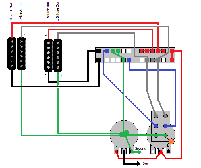 Normal: 1. AxB 2. A+B 3. B+C 4. C+D 5. CxD Push/Pull pulled: 1. A 2. A+B 3. B+C 4. C+D 5. C Thank u again! |
|
|
|
Post by reTrEaD on Feb 22, 2012 18:19:17 GMT -5
ReTrEaD, i actually want C on pos 5 with push-pull up... i mistyped :// C is probably a better choice than D. Farther from the bridge means it will sound a little less brittle. Then, based on your diagram I made this one. The only change I intended do make is this pos 5 with push-pull Can you please check it? Especialy pos 3 Everything seems to be correct. |
|
ulises
Rookie Solder Flinger
Posts: 1 
Likes: 0
|
Post by ulises on Mar 15, 2014 17:47:01 GMT -5
I think its time to post reTreAds version of my HHH design at this point. (i hope you dont mind reT!) Its a superswitch and two push pull pots, but it gets 5 series combos, 5 parallel combos and 5 single coil sounds, based on selecting five humcancelling pairs of coils, including Bridge Hb, M/B, M/N, B/N, Neck hb and then wiring them is series, parallel or just one coil. 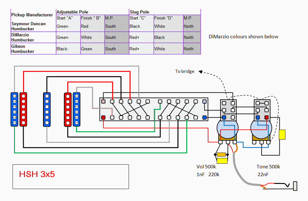 It gives more bang/buck! (BTW, congrats to asmith for figuring out how to do the original request) John |
|


