djeans
Apprentice Shielder

Posts: 46
Likes: 0
|
Post by djeans on Mar 30, 2012 16:59:18 GMT -5
This time, wired to guitar, switch on, 9v connected:
Pin 7: 6.60v
Pin 2: -2.79v
Pin 3: 0.00v
Pin 4: -2.175v
Pin 6: -1.568v
Not much difference, it seems. Weird.
I wonder if one of the components has failed . . . When connected to the guitar and in the off position, signal goes out to the amp. As soon as the switch is flipped, the audio cuts out completely. Removing / replacing the battery in this position creates a loud pop from the amp, but no audio otherwise.
|
|
|
|
Post by ashcatlt on Mar 30, 2012 17:29:29 GMT -5
I'm wondering that myself, though the numbers don't seem to indicate much unless the opamp itself is fried. You're sure that nothing coming from pin2 is toching the metal case of the opamp?
I'm still leaning toward rebuilding it. As you can see, it's not much more complex than pickup wiring. I have an unreasonable aversion to this idea of DC coupling the thing to the pickups, I'd AC couple it. That will require three more (biggish) caps and three 1M resistors.
The cap at the input is 10x smaller than a standard tone cap, and shouldn't affect guitar frequencies. Probably there to cut down on hiss.
|
|
djeans
Apprentice Shielder
Posts: 46
Likes: 0
|
Post by djeans on Mar 30, 2012 17:34:46 GMT -5
Pin 2 is connected to one side of the trim pot and the resistor with brown, green, orange, and gold bands. The other side of that resistor is connected to the switch, top right lug when looking at the diagram. That lug is connected to pin 6 as well.
The other side of the trim pot is connected to a resistor with 3 red bands and a gold band, which is connected to the final 2 resistors, and one side of the capacitor. That capacitor connects to the top left jack lug, along with pin 3.
The only place I can see where it hits the negative battery lead is from one of the last 2 resistors noted above. After the trim pot, it connects to ground, and then through a resistor with Gold, orange, blue, and green bands and out to the negative battery lead and pin 4, both of which are soldered to the side of the opamp.
The final resistor noted above goes from the ground (connected together with the other 2 resistors and the capacitor) to pin 7. Its markings are green, blue, orange, gold.
None of the connections appear to be shorting, or accidental. Every connection appears deliberate.
|
|
djeans
Apprentice Shielder
Posts: 46
Likes: 0
|
Post by djeans on Mar 30, 2012 17:39:13 GMT -5
I figured I would try that. Went to Radio Shack yesterday, and they didn't have any of the same parts - going to check out a local radio supply store here and see if they have the parts. If not, maybe I can source out the parts online. If it doesn't work, I would be interested in your suggestions on building a new one from scratch.
|
|
|
|
Post by reTrEaD on Mar 30, 2012 17:57:42 GMT -5
I moved the components around so it's easier to see the design. I omitted the switch for simplicity. 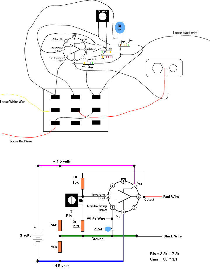  The resistors on the far left form a voltage divider. This "balances" the battery voltage around the "ground". The voltage at the + and - rails will change, as current from the output flows through the feedback resistor and input resistor. If the output goes positive, it will cause the voltage at the + rail to decrease and the voltage from ground to the negative rail will decrease. If the output goes negative, the opposite will happen. This shouldn't affect the gain, but it will limit the maximum output swing. Even with a perfect opamp, we wouldn't get anywhere near +/- 4.5 volts. I can't reconcile the voltage at pin 2 being more negative than the - rail. It just doesn't make any sense to me, even if the opamp was cooked. Pin 4 is directly connected to the battery (-). How can anything in the circuit be more negative than that?  |
|
djeans
Apprentice Shielder
Posts: 46
Likes: 0
|
Post by djeans on Mar 31, 2012 17:20:34 GMT -5
Ok,
I'm going to try to build another one with new parts - we'll see if it's a problem of a bad opamp, or if it's just a bad design.
Thanks again for all the help.
I'll report back with what I find after building the new one.
Darron
|
|
|
|
Post by reTrEaD on Mar 31, 2012 17:26:14 GMT -5
k, koo. talk to you soon.  |
|
|
|
Post by JohnH on Apr 1, 2012 4:24:31 GMT -5
Just a couple of questions:
has anyone worked out what this circuit would be expected to do?
and djeans, do you recall, when you first had it what it actually did? ie is it a clean booster that makes the sound louder, or did it change the tone?, or add distortion?
J
|
|
djeans
Apprentice Shielder
Posts: 46
Likes: 0
|
Post by djeans on Apr 1, 2012 5:50:36 GMT -5
When it was working, it would boost the gain and add distortion. On an already distorted amp, it would sound more over driven and have more sustain. On a clean amp sound it would sound gritty and distorted, but not in a useable way. - hope that makes sense.
I started building it today - I was able to find all of the parts except for the exact capacitor, and trim pot. The trim pot that was originally on it has 5k marked on it, the one I found is a 1k. Not sure how much of a difference that will make.
|
|
|
|
Post by reTrEaD on Apr 1, 2012 6:25:39 GMT -5
Not sure how much of a difference that will make. That will limit how low you can set the gain. Gain formula: Gain = Rf/Rin + 1 The trimpot and 2.2k resistor are in series, so even if the trimpot is set at zero, the lowest Rin can be is 2.2k. That's where the circuit gain is the highest (7.8). 15k/2.2k +1 With a 1k trimpot set at maximum resistance, the largest Rin can be is 2.2k + 1k = 3.2k. Gain = 15k/3.2k + 1 = 5.7 Even if the trimpot is extremely large, the gain can never be less than 1. And when the pot is set to zero resistance, the gain will still be 7.8 |
|
|
|
Post by ashcatlt on Apr 1, 2012 9:46:53 GMT -5
That's not really a whole lot of gain. It'll definitely be a noticeable boost, and you may see some clipping of loud peaks, but most of the guitar signal should come out of this thing clean most of the time. If it actually ends up biased as far off center as was measured above there will be more clipping of the negative side of the waveform, so maybe a little bit of asymmetrical overdrive sound. I can't figure out why it does that, though. Theoretically it should sit right at the halfway point. What it does to the input of the next active device it hits may be another story.
As we've established, it depends on being connected to the guitar in order to function at all. But I like to take voltage measurements before connecting it to the guitar. I think you could temporarily connect a resistor between the "loose black" ground wire and the input (white wire) to simulate the resistance of the pickups. The resistance value will no be critical. Somewhere in the range of your pickups would be good. Anything from maybe 3K to 10K or so. A straight wire even would probably work, but I want to see what the DC resistance of the pickups does to the bias.
So build it as drawn by retread, use alligator clips or whatever to connect that "pickup sim" resistor, connect the battery, and measure voltage at all the connected opamp pins. I'd personally prefer to see the voltages referenced to the bottom of the battery, but the ground wire will work, too.
|
|
djeans
Apprentice Shielder
Posts: 46
Likes: 0
|
Post by djeans on Apr 1, 2012 16:42:43 GMT -5
OK . . . . So, after rebuilding it, here are the voltages at each pin - 7: 4.211 6: .007 4 -4.048 3 0.00 2 0.00 And . . . . Preliminary test wired with alligator clips, it seams to work. Will post a vid of the sound on / off if any are interested once I get it installed and can say for certain that it is working. djeans PS My attempt at the preamp, came out cleaner looking than I expected, being that I'm not a seasoned solderer.  |
|
djeans
Apprentice Shielder
Posts: 46
Likes: 0
|
Post by djeans on Apr 1, 2012 17:31:01 GMT -5
So, after wiring it in and plugging into the amp, some good news, some bad. It does boost the gain when on, but the overall output of the pickups seems drastically reduced. I have to turn the amp WAY up before I start hearing anything, and would then have to turn it way down before switching to another guitar.
Also, the gain boost is clean - not the gritty gain boost I remember.
The trimpot seems to have no discernible affect - sweeping the full range of the pot does nothing. The pot might be defective tho, as it turns freely with no stop at either end - it just keeps turning.
I'm wondering if there might be a short somewhere. When I first plugged it in, it seemed right, then the output dropped noticeably after about 20 seconds.
hmm. . .
|
|
djeans
Apprentice Shielder
Posts: 46
Likes: 0
|
Post by djeans on Apr 1, 2012 19:39:23 GMT -5
Ok, here is a video where you can hear the sound of the preamp installed.
Any ideas on why the output of the guitar dropped so significantly after installing the preamp?
Thanks again for everyone's help.
|
|
djeans
Apprentice Shielder
Posts: 46
Likes: 0
|
Post by djeans on Apr 3, 2012 18:19:31 GMT -5
Ok,
I discovered one thing I did wrong. The new trimpot had 3 lugs, where the old one only had 2. I connected to the two outside lugs, which apparently is the max resistance. After reconnecting it, it is much higher output. Still not as hot as the other guitar without the pre-amp on, but definitely hotter. Not sure if the difference in tonal characteristics of the wood could account for that or not. The other guitar is Padouk, this one is Alder I think.
|
|
|
|
Post by cynical1 on Apr 3, 2012 20:31:46 GMT -5
How did the output of the two guitars compare before you but the pre-amp in?
HTC1
|
|
|
|
Post by ashcatlt on Apr 3, 2012 21:16:08 GMT -5
He said it's the same model pickup in both guitars, and from what I heard its a drastic difference. Wood wont account for that. String-to-pickup distance could make some difference, but I don't know, it's really frickin quiet!
What concerns me most is that the bypass signal is also very quiet. This is a real True Bypass wiring and the booster circuit should have absolutely no effect on the bypassed output.
The only thing I can think is maybe you wired the switch wrong. 3PDTs are basically square with three sets of three lugs. You wouldn't be the first to get the rows confused with the columns. Course, these are more often stomp switches. Seems the action of the toggle would be a clue. In fact, IIRC, retreads covered that earlier. And I haven't actually looked to see if this could possibly cause your problem anyway.
My first suggestion for debugging is to put the thing in bypass, plug in a cable, and read resistance between the tip and sleeve at the other end of the cable. Then do the same with your other the other axe. Then report back your findings.
I tend to think that the issue is not with the preamp itself.
Other issues raised along the way:
The trim pot should stop at either end of its travel. There is such a thing as a multi-turn trimpot, but I think even those stop eventually. Yours looks like the plain Jane RS variety anyway. Max resistance there means minimum gain, but there's still a boost even then, and it cant cause the problem you're experiencing.
The cap value is not super critical, as long as the multiplier is correct. If you get up to where there's a 4 as the final digit you're into the range of the caps we put on our tone controls. If it was a lot bigger than that, it would roll off all of the guitar frequencies and might come across as a general reduction in volume. I don't think that's the issue here either, but not a bad idea to check.
|
|
djeans
Apprentice Shielder
Posts: 46
Likes: 0
|
Post by djeans on Apr 5, 2012 3:56:39 GMT -5
The guitar had been on loan to a friend for awhile, and when I got it back, I took it apart cleaned it up, and put the Bill Lawrence L500XL in the bridge position and then put it back together. I didn't really start playing around with it much before embarking on this project, but it seemed very similar to my other guitar when I plugged it in once I got it all put back together. Here are the findings - Reference guitar - 15.1 kΩ - It should be noted that while both guitars have a Bill Lawrence L500XL pickup in the bridge position, they aren't quite apples to apples - There are 2 different companies selling these pickups, Bill Lawrence USA and www.billlawrence.com (Bill & Becky) - and I have one of each. The reference guitar has the Bill & Becky pickup, the project guitar has the Bill Lawrence USA pickup. Preamp Bypassed - 250.0 kΩ Preamp On - 5.6 kΩ Preamp removed from guitar 11.5 kΩ All measurements were taken from the tip and sleeve of a 6 inch patch cable with the volume knob at 100%. I figured out what I had done wrong there. I bent one of the lugs so that it was out of the way, not realizing that the other end of that lug had a nub on it which acts as the stop. I plan on replacing that with a different pot I found at an electronics store. The capacitor is a .003 uF - I don't know much about capacitors, or how to read them, but the guy at the electronics store felt it was a close approximation of what I had. |
|
djeans
Apprentice Shielder
Posts: 46
Likes: 0
|
Post by djeans on Apr 5, 2012 5:13:12 GMT -5
I went ahead and replaced the trim pot with a better one (5k) and replaced the capacitor with another that I bought (.0022MFD 630VDC) - this one is physically larger than the others . . . it is huge. . . and now, here are the readings
Preamp Bypassed - 11.66 kΩ
Preamp On - 2.18 kΩ
When I plugged it in and played it, it sounded pretty equal to the other guitar with the preamp off - and maybe a little hotter with the preamp on.
I think that's about as good as it's going to get. Would you guys agree?
|
|
|
|
Post by reTrEaD on Apr 5, 2012 7:29:12 GMT -5
When I plugged it in and played it, it sounded pretty equal to the other guitar with the preamp off - and maybe a little hotter with the preamp on.
I think that's about as good as it's going to get. Would you guys agree? No, I think it could be a ton hotter with the preamp on. According to the gain calculations, it should be considerably hotter with the preamp on. A gain of 7.8 (when the trimpot is at minimum) would be equal to 17.8dB. That should seem like about 3 times as loud as when the preamp is bypassed. If the boost when the preamp is on seems considerably less than that, double check the resistors in the feedback loop. Maybe you're off by a factor of ten on one of them. (wrong color on the third band) The color codes should be: 15k - Brown, Green, Orange 2.2k - Red, Red, Red If the resistors are correct and you are presently getting the expected gain, there is no reason to assume this is "as good as it gets". A few changes in the resistors can get you MUCH more gain, if desired. |
|
|
|
Post by ashcatlt on Apr 5, 2012 9:21:32 GMT -5
There was something seriously wrong somewhere when you got that 250 K reading. None of what you replaced accounts for it. I think you just accidentally fixed it in the process of messing with the preamp.
Either of the cap values would have been fine. The most recent one is huge physically because it's built to handle 630V! That's like a thousand times what your guitar will put into it. Doesn't hurt anything, aside from being huge.
The gain will be highest with the trim pot all the way down. If that doesn't give a serious boost the either the resistor to ground is too big or the other resistor in the feedback loop is too small. Like retread said, you could get something like 7V (and a pile of distortion) out of the thing if you changed out one of those resistors. Not that you'd want to go that far.
|
|
djeans
Apprentice Shielder
Posts: 46
Likes: 0
|
Post by djeans on Apr 5, 2012 18:01:01 GMT -5
I checked, and I had the trim pot adjusted all the way the other way. I figured it was similar to a volume pot, where turning clockwise increased the output - turning the other way made a huge difference.
I think you're right on there. When I first plugged it in after changing the trim pot and cap, I hadn't put the back plate back on - everything seemed fine - after putting the plate on, I was back to a weird low output and 250k on the meter. I think the plate was pushing on some of the wires and causing something to short - took the plate off and made sure there was clearance between all the wires and taped off a few things - all seems right now.
I couldn't have figured this out on my own, thank you so much for everyone's help. This guitar is more of a sentimental project for me, but it meant a lot to me to get it restored back to where it was.
Here is a clip of how it sounds now, for those interested.
|
|
|
|
Post by reTrEaD on Apr 5, 2012 21:31:25 GMT -5
Here is a clip of how it sounds now, for those interested. nice. wanna go farther? |
|
djeans
Apprentice Shielder
Posts: 46
Likes: 0
|
Post by djeans on Apr 6, 2012 2:06:15 GMT -5
Of Course |
|
|
|
Post by reTrEaD on Apr 6, 2012 7:31:17 GMT -5
Okay then... Here's somewhere you could go. I'd suggest getting a new switch, opamp, etc. That way you will still have the original intact, if you don't like the new version. But you could modify the original, if desired. There are 2 new resistors that will replace existing resistors, one 50k pot replacing the existing 5k pot, and the 5k pot would be repurposed to attenuate the output. Basically a volume control. Compare the old circuit to the new circuit: 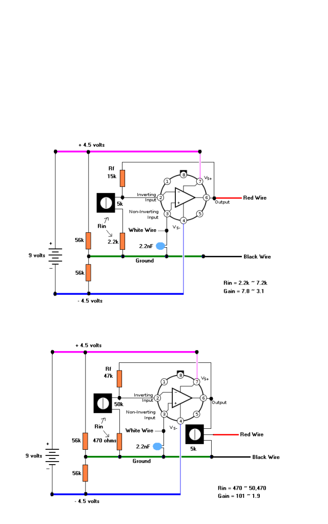 We have a ton more gain available. This should allow for serious distortion at the output of the opamp. But since the output level will be very large, the 5k pot will be used to scale the output back down to something manageable. |
|
djeans
Apprentice Shielder
Posts: 46
Likes: 0
|
Post by djeans on Apr 6, 2012 13:48:38 GMT -5
Sweet. I bought two of everything the first time around in case I messed something up. So, I think I have everything I need except for, the new resistors, and the new trim pot. I'll try to find those this week, and I'll get started.
|
|
|
|
Post by ashcatlt on Apr 6, 2012 15:14:32 GMT -5
I'm thinking that you might want a little more tone shaping here when the thing starts distoring. Opamp clipping can come across kind of harsh and "fizzy".
If we put the variable resistor in the feedback loop - in series with a much smaller Rf - and the strap a capacitor in parallel with these, it'll reduce the proportion of treble as gain is increased. It'll be mostly flat at low gain settings, but will roll of some of the nastiness when you turn it up.
Just a thought.
|
|
djeans
Apprentice Shielder
Posts: 46
Likes: 0
|
Post by djeans on Apr 7, 2012 17:36:09 GMT -5
I understood that in a general sense, but not in a real literal way. Could you be more specific about what I would need to connect where?
|
|
|
|
Post by ashcatlt on Apr 7, 2012 20:16:15 GMT -5
Probably be easier to draw it, but I ain't gonna do that now.
If you look at retread's new scheme you'd basically be swapping the pot>resistor structure with the 47K resistor. Then, though, you'd reduce the value of the 47K (which will now be from inverting input to ground) to 470 ohm.
Then you put a cap (not sure on the value here, would have to spice it. The Rat uses 100pf, but all of the resistances are different...) from the opamp's output to the inverting input.
|
|
|
|
Post by reTrEaD on Apr 8, 2012 11:30:03 GMT -5
Then you put a cap (not sure on the value here, would have to spice it. �The Rat uses 100pf, but all of the resistances are different...) from the opamp's output to the inverting input. This part looks pretty good. At higher gain settings, the cap is more "effective" as a high-cut filter. The hf rolloff frequency moves progressively lower. Then, though, you'd reduce the value of the 47K (which will now be from inverting input to ground) to 470 ohm. This part is setting off alarm bells. Since the voltage between the inverting input and ground will "mirror" the voltage between the non-inverting input and ground, this will require a significant amount of current, regardless of the gain setting. I'm not particularly bothered by this, if it only occurs at high gain settings (as in the circuit I drew). This means that there will come a point toward the maximum gain settings where the output will become severely limited. But at lower gain settings, life is good. So we could increase the gain to get the desired amount of clipping, then attenuate the output to a manageable level, by use of the voltage divider on the output. But that won't happen with such a small fixed resistor for Rin. With Rin fixed at 470 ohms, we need a feedback current of 2mA per volt of input signal. Let's look at what happens with a modest guitar signal. With a 100mV signal input, the current must be 0.2mA. Doesn't sound like much of a problem until we look at where that current has to go. Since the only return path is through the bottom "balancing" resistor, we know that we will have at least 0.2mA through a 56k resistor. That indicates a voltage drop of over 11volts. Not gonna happen with a 9volt battery, even if the "ground" was pulled all the way up to the + supply rail. We'll have a severely clipped signal and the output will likely be smaller than the input. Instead of being able to gradually dirty up the signal as we increase the gain, this circuit will be filthy right out of the gate. |
|