phatmarx78
Apprentice Shielder
 I sling Fenders topped with Marshalls and Boss'
Posts: 49
Likes: 0
|
Post by phatmarx78 on Mar 29, 2012 15:11:49 GMT -5
Hello all! I have just joined this forum! It looks like their are many guitar enthusiasts that could help me in my wiring dilemma. I am trying to wire my 57 duo sonic like a jagstang. I am going to post everyone a diagram. Heres my rundown.. I cannot use the regular 8 pole on-off-on slide switches in this guitar. They will not fit. I am instead using an on-off-on toggle, witch only has 6 poles. These toggles will fit, no problem. This hole project is a very long story. I contacted a local tech to ask their opinion about how the switches would work if their are 2 less pins than the other. I drew him up a small schematic, faxed it to him, and e took a look and said that it should work fine. I asked on other forums, with one answer questions, like "yes". I did wire it how I drew it out. My results are as is... Neck pickup on-off-on;; they all work accordingly, but I cannot ear a significant sound difference between the two on's like I would on a Jagstang. Bridge Pickup on-off-on;; the one on position works. The off works I suppose, because it should turn the pup off, and the third third position, being on, turns off everything, not even a ground buzz, just totally kills all feedback. Here is the schematic I drew up:  Can someone tell me what is up with this scheme? Why wont it work?? Thanks in advance. Oh yeah, I have the guitar apart now. Any quick info would be appreciated! |
|
|
|
Post by reTrEaD on Mar 29, 2012 16:39:11 GMT -5
Hello all! I have just joined this forum! It looks like their are many guitar enthusiasts that could help me in my wiring dilemma. Hi. Welcome to Guitarnutz2! I am trying to wire my 57 duo sonic like a jagstang. Jagstang is wired like a Mustang. Fairly simple. I cannot use the regular 8 pole on-off-on slide switches in this guitar. They will not fit. I am instead using an on-off-on toggle, witch only has 6 poles. These toggles will fit, no problem. We like to refer to those as "lugs" rather than poles. The term "pole" is a little more specific and implies a common connection or wiper. In a case where the middle lugs of an 8 lug slide switch are tied together (Like a Mustang or Jagstang) you definitely CAN use the 6 lug on-off-on variety of slide switch. But you must be certain the center position is open, connecting the middle lugs to nothing. If the center position bridges to both outer lugs, it won't work. I asked on other forums, with one answer questions, like "yes". I hope we can be more helpful than that.  I did wire it how I drew it out. My results are as is... Neck pickup on-off-on;; they all work accordingly, but I cannot ear a significant sound difference between the two on's like I would on a Jagstang. You should definitely NOT hear a difference between the two ON positions, if only one pickup is being used. You will only hear a difference between the two on positions when BOTH pickups are on. Bridge Pickup on-off-on;; the one on position works. The off works I suppose, because it should turn the pup off, and the third third position, being on, turns off everything, not even a ground buzz, just totally kills all feedback. Here is the schematic I drew up: Can someone tell me what is up with this scheme? Why wont it work?? Thanks in advance. The wiring to the neck pickups switch looks good. The wiring to the bridge pickup switch is wrong. I suggest wiring the bridge pickup to the center lugs of the bridge pickup switch the same way as you have the neck pickup. Create an "X" with jumper wires, the same way you have on the neck pickup switch. Connect a jumper from the upper left lug of the neck pickup switch to the upper left lug of the bridge pickup switch. Connect a jumper from the upper right lug of the neck pickup switch to the upper right lug of the bridge pickup switch. Connect the black wire from the volume control to the upper left lug of either pickup switch. Connect the red wire from the volume control to the upper right lug of either pickups switch That should do it. When you're done the you will have 4 sounds, just like on a Mustang or Jagstang. Neck only Neck and Bridge Neck and Bridge out of phase Bridge only One pickup out of phase sounds the same as if it is in phase Both pickups out of phase sounds the same as both pickups in phase. Bridge out of phase and neck in-phase sounds different from having both pickups in phase. Bridge out of phase and Neck in-phase, sounds the same as Bridge in phase and Neck out of phase. |
|
phatmarx78
Apprentice Shielder
I sling Fenders topped with Marshalls and Boss'
Posts: 49
Likes: 0
|
Post by phatmarx78 on Mar 29, 2012 16:50:08 GMT -5
;D
Im tickled right now!!! I have found the site in with I may ask for help and receive proper guidance!!!
Thank you soooooo much!!! I have one other favor to ask....
Could you maybe mock up a drawing of the what your saying?
Im a little slow to all the new terminology, and can learn quite fast visually!
|
|
phatmarx78
Apprentice Shielder
I sling Fenders topped with Marshalls and Boss'
Posts: 49
Likes: 0
|
Post by phatmarx78 on Mar 29, 2012 16:57:41 GMT -5
Oh my! I think I have made a mistake as well...  The bridge pickup is the one that "works", and the neck pickup is the one that does not... Sorry for the confusion!! |
|
|
|
Post by reTrEaD on Mar 29, 2012 17:34:57 GMT -5
;D Im tickled right now!!! I have found the site in with I may ask for help and receive proper guidance!!! Thank you soooooo much!!! I have one other favor to ask.... Could you maybe mock up a drawing of the what your saying? Im a little slow to all the new terminology, and can learn quite fast visually! I found a Mustang diagram though Google. It accomplishes the same task, but not precisely as I described. Note the "X" between switches to keep the phase relationship the same, when the switches are pushed in the same direction. Same concept as what I had described, but with shorter wires.  The two lugs in the middle of these 8 lug switches are jumpered together. Treat them as the one lug in the center of a 6 lug on-off-on switch. The extra wires to connect the metal frame of the switch (upper right of the neck switch and lower left of the bridge switch) are not necessary if you have a shielded pickguard that is grounded. Their only purpose is to connect the metal case to ground, providing some shielding. |
|
phatmarx78
Apprentice Shielder
I sling Fenders topped with Marshalls and Boss'
Posts: 49
Likes: 0
|
Post by phatmarx78 on Mar 29, 2012 17:41:43 GMT -5
The guitar is not grounded!! These old duos did not have anything to ground!! Could this be a reason why my drawing did not work??
What your saying is what the local tech is saying.. But I got the same results... i tried to follow this method with a jagstang diagram, thinking the "extra" lugs were just grounds...
Now I'm thinking its not producing because of no ground....
Im gonna post another diagram I drew comparing the jags wiring without the extra 2 lugs.
|
|
phatmarx78
Apprentice Shielder
I sling Fenders topped with Marshalls and Boss'
Posts: 49
Likes: 0
|
Post by phatmarx78 on Mar 29, 2012 17:46:37 GMT -5
Here it is, the ground is something I drew, because it was on the Jagstangs diagram, but the old duos didnt have something to ground to...  I have been trying different styles for the past 2 hours. but nothing gives... I just want the duo to play like the jag! |
|
|
|
Post by newey on Mar 29, 2012 19:08:03 GMT -5
pm78-
Hello and Welcome to G-nutz2!
RT has already given you the goods on the conversion here, I don't have much to add, except that your latest diagram doesn't look like the Mustang/Jagstang wiring RT posted. Both pickup's switches should be basically identical.
If your guitar truly had no "ground", you wouldn't get any sound out of it, because you won't have a completed circuit. The "sleeve" (or "barrel", as it is sometimes called) connection at the output jack is your ground. This connects to the back of one of your pots, where other grounds are collected together and soldered. This would include the negative connections from the pickup switches, as well as the grounds from the switch frames.
You should also have a string or bridge ground, which is likewise connected to the back of a pot somewhere.
|
|
phatmarx78
Apprentice Shielder
I sling Fenders topped with Marshalls and Boss'
Posts: 49
Likes: 0
|
Post by phatmarx78 on Mar 29, 2012 19:50:26 GMT -5
Thanks for the welcome!! I feel very much so at home!
I know about the two ground wires. If you have ever seen the jagstang wiring diagram from Fender themselves, it is wired exactly how I have drawn it above. (the switches diagram) Also on the drawing from fender, their is no ground going to the input jack, just one to the bridge.
I added some shielding tape to the body, and made a point to connect the volume pot's ground to the shielding on the body, but still nothing to the jack.
The two switches that I have drawn together are of (on the right) a Jagstang, and (on the left) what I have drawn myself, the proposed method.
Im trying to get IN and OUT of phase sounds from the guitar.
The jagstang produces both. If I could, I would put two slide switches with 8 lugs so that it would be perfect, but they do not fit, and I need to use two toggle with 6 lugs.
Why is mine not working??
Im starting to think it will not work, and that I will have to get a custom pickguard made and redo all the electronics so that everything fits and I can get my sound right, but I would much rather figure this out!!
Thanks again for all the input guys!! Every bit will help!
|
|
|
|
Post by newey on Mar 29, 2012 21:26:56 GMT -5
OK, well then we first have to agree on what wiring we're talking about. Both RT and I were assuming that the Jagstang wiring was the same as the Mustang wiring.
You have shown something different. I checked Fender's website, but I couldn't locate a Jagstang wiring diagram, so I'll have to take your word that it's as you show it.
On a Mustang, there are two slide switches, one for each pickup. Each switch gives you one pickup ON- OFF- ON OOP (Out of Phase).
The stock mustang switching is redundant, in the sense that there is no need to put both pickups out of phase, that just puts the pair back in phase with each other and doesn't give you any new sounds.
The switching you show for the Jagstang has one switch to control the neck pickup ON-OFF- ON OOP, but the bridge pickup isn't put OOP, it's just turned on and off, as: ON-OFF-ON.
So, this switching also has a redundant position, since moving the bridge switch either way turns it on.
But we first have to agree on what the goal is.
If you want it the way you have shown it, you have correctly translated the diagram over from the 8-lugged slide switches to your toggle switches.
I don't know what you mean by "still nothing to the jack".
Presumably, your jack is connected to something?
In any event, if it is wired as you have shown the Jagstang, you should get:
Neck switch: On/Off/OOP
Bridge switch: On/Off/On
You still have the same 4 sounds as with the Mustang, the only difference is how you switch to the different settings. With the Mustang wiring, when both pickups are "on", sliding either pickup switch all the way over to the opposite side gives you the OOP sound.
With the Jagstang wiring as you show it, only sliding (or toggling, in your case) the neck switch over gives you the OOP sound, sliding the bridge switch over all the way doesn't change anything. (Of course, with either switch, traveling through the center position will briefly turn the pickup "Off").
|
|
phatmarx78
Apprentice Shielder
I sling Fenders topped with Marshalls and Boss'
Posts: 49
Likes: 0
|
Post by phatmarx78 on Mar 29, 2012 21:45:18 GMT -5
I mean that their is no ground to the jack at all. Thats the thing that makes the jagstang so much more unique, to me at least. Here are the wiring pictures and the sounds you can achieve with them. This is my goal overall. But when I wire it like we have talked about in my comparison drawings, I get no sound in the bridge pup in one "on" position. And like I said before, their is no sound difference to the necks "on " "on", but I am sure their are different sound with the Jagstang. Im still not sure whats wrong with my wiring. It should achieve the same things...    Oh and heres a picture of my boys together, just for show of course!  |
|
phatmarx78
Apprentice Shielder
I sling Fenders topped with Marshalls and Boss'
Posts: 49
Likes: 0
|
Post by phatmarx78 on Mar 29, 2012 21:58:40 GMT -5
Heres how my toggles work.
Neck: on-off-on, only the 1st position on works. I guess the second position off works, and then the 3rd position on just kills the whole guitar, no sound at all, not even a hum from local electric activity..
Bridge: on-off-on They work, I suppose. The 1st position on gives sound, the off shuts off, and the 3rd position on produces sound.
|
|
|
|
Post by newey on Mar 29, 2012 23:01:54 GMT -5
OK, so it's the neck switch that's the problem. I thought you had originally said the bridge switch wasn't giving you output in one position.
The switching, per your list, is just as I have described it. The bridge switch just turns that pickup on, regardless of which way the switch is pushed away from the center position. Four separate tones available, as noted.
It has to be connected or you would have no sound. Since the Jagstang has a metal plate for the controls, the jack can be grounded by the barrel touching the metal plate, which in turn contacts the volume pot shell. It's connected, there's just not a wire.
I wouldn't trust that plate to make a good connection, I'd run a separate wire. Relying on the plate to make the ground connection is a fairly cheesy way to do it, although from Fender's perspective it saves the cost of a piece of wire.
That is not, however, your problem, since you are getting some output.
You should double-check the connections to the neck switch, maybe hit them with your iron once again. Any further troubleshooting will require a multimeter. Ideally, you'd de-wire that switch and test it to be sure the problem isn't internal to the switch.
|
|
phatmarx78
Apprentice Shielder
I sling Fenders topped with Marshalls and Boss'
Posts: 49
Likes: 0
|
Post by phatmarx78 on Mar 30, 2012 2:10:17 GMT -5
 As embarrassing as it sounds to me, I don't have a multi meter.. I might have to just try rewiring another toggle switch, and troubleshoot manually. Im just not sure if the switch is the problem. I do leave two lugs completely separated from other connections. I will probably have a go at this tomorrow evening or later in the night depending on how the day treats me. Or I might just go out and finally get a meter. If I do that, I will need to know how to test it, I know its basic functionality, but not how to work the tool itself...
|
|
|
|
Post by newey on Mar 30, 2012 6:01:23 GMT -5
I'm not sure it is either, it's one possibility. A bad connection is far more likely to be the culprit. Your toggle switches connect like this in the three positions: 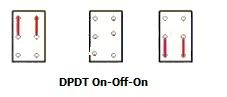 The red lines show the internal switch connections in each switch position. In the center position, nothing is connected. Note that the position of the toggle switch lever is opposite of the internal connections. As shown in my diagram, the lever is pointing "down" in the first drawing, and "up" in the third drawing. So, look at the switch with the lever in the position where you are getting no output. You'll want to focus on the upper or lower lugs, depending on which switch position is the bad one, as described above. (Since I can't see your guitar, I can't tell you which way the switch is oriented or which side has the bad connection.) The two center lugs on the switch are the "common" or "pole" lugs. Since you do get output from the switch when it is set the other way, the center connections are not your problem. So, in order: Figure out which connections are likely to be the problem, based on the above discussion, and check or re-solder those connections. Of course, you need to check both ends of each wire, since the problem may not be at the switch end, but also where the wire is connected. In particular, if the ground connection from the switch is going to a pot, that's a likely spot for a bad connection. If that doesn't solve the problem, and since you don't (as yet) have a multimeter, swapping out the toggle switch for another would (likely) tell you if the switch was bad. But, again, that's a less likely scenario, particularly if these are new switches. |
|
|
|
Post by newey on Mar 30, 2012 6:05:29 GMT -5
I'm not sure what you mean by this. Posting some close up photos of your wiring might help sort this out as well.
|
|
phatmarx78
Apprentice Shielder
I sling Fenders topped with Marshalls and Boss'
Posts: 49
Likes: 0
|
Post by phatmarx78 on Mar 30, 2012 6:31:57 GMT -5
I just meant that two lugs are unused. On the jags tang diagram, their are three lugs unused, mine simply has tow unused. I will have it apart later today. I will snap some photos of it to show you exactly what I'm working with. Last night I did resolver everything back to my original wiring schematic. I got all the same original results that I described above. But like I said, I will post some pictures at one point today.
|
|
phatmarx78
Apprentice Shielder
I sling Fenders topped with Marshalls and Boss'
Posts: 49
Likes: 0
|
Post by phatmarx78 on Mar 30, 2012 7:09:50 GMT -5
|
|
|
|
Post by newey on Mar 30, 2012 14:44:27 GMT -5
As per your diagram of the Jagstang wiring, the neck switch has an "X" of wires. This switch, as shown by your diagram, should not have any unused lugs, all six should be wired.
The bridge switch had three unused lugs as shown in your Jagstang diagram. Those thre become two unused lugs, since you are using the toggle switches instead of the slide switches. If you were to wire that switch like the neck switch, all 6 lugs would be used- it would look like the Mustang diagram RT posted.
I just want to be sure we're not confusing the two switches here.
In the first photo of your wiring, it looks like it should be showing the neck switch, since it is the one closest to the "horn" of the pickguard. If so, it doesn't look like that wiring follows the diagram. First, I'm not seeing the "X" of wires, from top right lug to bottom left lug and from bottom right to top left.
Second, it looks as if the black wire which is coming from the other switch and which is soldered to the lower right lug is also contacting the lower center lug. It also looks like the two red wires on the right side contact each other.
And, all of the wires to that switch have substantial lengths of uninsulated wire before the solder joints. Any of those uninsulated wires could be making contact somewhere they shouldn't be, once you install the pickguard and tighten it down- you may not even see the problem once you take the guard off. But you may need to wrap the uninsulated ends of those wires with some electrical tape to be sure they'r enot shorting out to something.
Also, I am not sure, based on some of the statements you have made, whether you fully understand the Jagstang wiring you are trying to implement.
The neck pickup is put out of phase by its switch. The OOP setting makes no difference in the sound of the neck pickup unless the bridge pickup is also on as well- a pickup can only be OOP with respect to something else, it can't be out-of-phase by itself. When the bridge pickup switch is "off" (in the center position), moving the neck pickup switch will not change the sound at all.
On the bridge switch, both ends are the same, the pickup is "off" when the lever is centered, and "on" when the lever is either to the left or to the right. Moving that switch left or right will not change the sound of the guitar (except by turning the bridge pickup off, in the center).
Hope that helps!
|
|
|
|
Post by reTrEaD on Mar 30, 2012 15:39:32 GMT -5
And, all of the wires to that switch have substantial lengths of uninsulated wire before the solder joints. Any of those uninsulated wires could be making contact somewhere they shouldn't be, once you install the pickguard and tighten it down- you may not even see the problem once you take the guard off. But you may need to wrap the uninsulated ends of those wires with some electrical tape to be sure they'r enot shorting out to something. Hard to tell from the photos because I can't change the viewing angle, but it looks like there might be some solder bridges too. |
|
phatmarx78
Apprentice Shielder
I sling Fenders topped with Marshalls and Boss'
Posts: 49
Likes: 0
|
Post by phatmarx78 on Mar 30, 2012 16:38:52 GMT -5
So then that is what I have achieved.... I believe..
Just to clear things up, I put the bridge pickup switch closest to the horn of the guard. The switch for the neck gives sound with only one of its "on" positions, the other just kills the guitar completely, and I suppose the "off" position works, as it turn the pup off. Thats what I don't understand. Why will it not produce sound in its second "on" position? The bridge pickup works both ways, sending out sound in both "on" positions, and turns off, respectively, in the "off" position.
So picture it like this, if it is fully installed on the guitar..
Neck pup: AWAY-ON
MIDDLE-OFF
TOWARDS-ON------NOT PRODUCING SOUND
Bridge pup: AWAY-ON
MIDDLE-OFF---------- ALL WORK
TOWARDS-ON
Just to reiterate, the bridge pup switch, with is closest to the horn of the pickguard, work. The neck pup switch works only in two positions.
Those Jagstang drawings come directly from Fender themselves, the duo sonic is just what I translated.
So if I were to compare my Duo's switches possibilities to the one of Fenders Jagstang, here is what I would have;
3 position switch 1 :::: 3 position switch 2 :::: Result
Left:::: ::Left Neck/Bridge
::Right ??(should be oop, but no sound)
::Center Neck
Center (off):::: ::Left Bridge
::Right ??(should be bridge, but no sound)
::Center Both Off
Right:::: ::Left ??(should be ip, but no sound)
::Right ??(should be ip, but no sound)
::Center ??(should be neck, but no sound)
|
|
|
|
Post by newey on Mar 30, 2012 18:33:38 GMT -5
I understand that the neck switch isn't working in the one position. But I can't tell what you mean here, since we haven't clearly designated which switch is which as far as the wiring goes (ignoring its position in the guitar. It is important that we talk precisely if we are to be able to help you. So, I've drawn up what we call a "truth table" showing what you should be getting in each of the switch positions. Again, I understand that you aren't getting this with the neck switch in the one position. It looks like it's the out-of-phase that you're missing at that position. Why all output is (apparently) shorted at that position is also a mystery. The bad switch position would be represented by the very bottom row in my truth table. I have also defined what we mean when we say a switch is "up" or "down" with reference to the diagram. 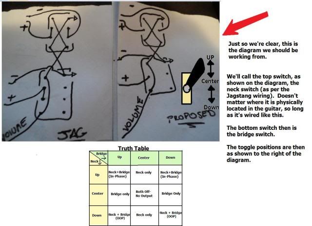 This, then, will hopefully get us all talking about the same things here. Now, as far as the wiring problem, both RT and I have asked you to verify some things with the wiring, back at posts #18 and #19. Please respond to those items and we'll go from there. |
|
phatmarx78
Apprentice Shielder
I sling Fenders topped with Marshalls and Boss'
Posts: 49
Likes: 0
|
Post by phatmarx78 on Mar 30, 2012 19:17:22 GMT -5
I am so sorry if I have missed the questions you guys have asked!! I read back and can't quite seem to see what you are asking of me!
I am relatively new at the terminology, but I am trying hard to catch on. Could you please ask me directly what you would like to know now?
Also, your truth table that you have made is exactly what I am trying to accomplish, to the "t". Im sorry if my table did not come out correct, it looked fine when I went to post it, but came out wrong, but your table is exactly what I was trying to communicate.
I can't tell you how much this means to me, you guys helping as a tag team that is. Please bare with me if I am slow to understand what you are asking for, I would be happy to answer all your questions, I just can't understand what your asking in the previous posts!
|
|
|
|
Post by newey on Mar 30, 2012 20:36:13 GMT -5
Specifically, please check for any solder bridges, as RT mentioned. The photos do make it look like there's some contact in a couple of spots.
Also, please verify that your neck switch is wired exactly as the top switch is shown on the diagram. I was mistaken as to which switch you had closer to the "horn", but then the lower one is the Neck switch- and that one doesn't look right to me either, although it's hard to tell much from the photos about that switch.
|
|
phatmarx78
Apprentice Shielder
I sling Fenders topped with Marshalls and Boss'
Posts: 49
Likes: 0
|
Post by phatmarx78 on Mar 30, 2012 20:48:38 GMT -5
As for the solder "bridge", I think your referring to the to joined lugs I connected with the black wire. This was just the ground. The only reason I put it their was to try and mirror the neck switches wiring. I have re-soldered it back to where it should be, as per the jagstang wiring drawings.
I can also confirm that the neck switch is wired like the original drawings that you have posted with your notes and my drawings. It is wired like those.
|
|
|
|
Post by newey on Mar 30, 2012 22:31:23 GMT -5
OK, on the assumption that it's the OOP setting that you're missing at the neck switch, check these connections:  If those all look good, and since you don't have a meter, swapping out the neck switch to be sure it's good is really the only other suggestion I have to offer. Problem is, without a multimeter to check the switch, you can't be sure the new one you put in is good, although the odds that two would both be bad are pretty slim. If that checks out, further troubleshooting is going to require a multimeter. Actually, to test the switch, a continuity tester is all that's really needed, you can make one of those out of some scrap wire, a flashlight bulb, and a battery. But a multimeter is certainly handy to have if you're going to be rewiring guitars (or other things, for that matter . . .) |
|
|
|
Post by reTrEaD on Mar 31, 2012 6:54:40 GMT -5
Heres how my toggles work.
Neck: on-off-on, only the 1st position on works. I guess the second position off works, and then the 3rd position on just kills the whole guitar, no sound at all not even a hum from local electric activity..
Bridge: on-off-on They work, I suppose. The 1st position on gives sound, the off shuts off, and the 3rd position on produces sound. Something is causing a short from "guitar hot" to "guitar ground" in that 3rd position of the neck switch. The neck pickup has one wire always connected to ground or hot. This extra connection doesn't cause any problem in the 1st or off position, but causes hot and ground to be joined together in the 3rd position. 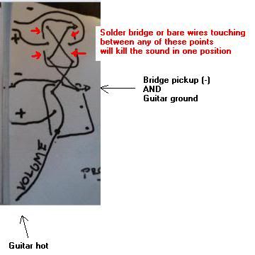 Look for solder bridging between adjacent lugs at any of the red arrows. Or bare wires touching each other. |
|
phatmarx78
Apprentice Shielder
I sling Fenders topped with Marshalls and Boss'
Posts: 49
Likes: 0
|
Post by phatmarx78 on Mar 31, 2012 9:52:42 GMT -5
Ok guys, I definitely can confirm that their are no solder bridges in the connections. I have yet to swap out the toggle switch though. I will probably try that today. However, these switches are all brand new.
|
|
phatmarx78
Apprentice Shielder
I sling Fenders topped with Marshalls and Boss'
Posts: 49
Likes: 0
|
Post by phatmarx78 on Mar 31, 2012 10:19:37 GMT -5
Okay, I just rewired a new switch on it. Nothing.....  Im not sure whats up.... No solder bridges, no switch failures/faults.... Somethings got to give!!! Im beginning to think that a Jagstang can only be wired like a Jagstang, with an 8 lug slide switch.. Im just not sure if a 6 lug toggle can dish it out.. Could this be a simple but obvious reason? |
|
|
|
Post by reTrEaD on Mar 31, 2012 10:59:12 GMT -5
Im beginning to think that a Jagstang can only be wired like a Jagstang, with an 8 lug slide switch.. Im just not sure if a 6 lug toggle can dish it out.. Could this be a simple but obvious reason? No, that's definitely not the reason. Even if you had the wrong type of switch (on-on-on) the only problem would be in the center position, not at one of the outer positions. Let's go back to this drawing and ask some questions... Is the wiring for the neck bridge (upper) switch exactly as the drawing shows? The pickup (+) is on the left center lug? The guitar hot (connection that eventually makes its way back to the volume control) is on the lower right and upper left lugs? Which is the 3rd position (the one that doesn't work) of the toggle? Is it when the toggle is toward the neck or toward the bridge? |
|


