|
|
Post by ashcatlt on Apr 3, 2013 9:42:35 GMT -5
Take another look at that bridge V there. It should be wired like the neck's. Right now it's just a static resistor to ground.
|
|
|
|
Post by silencer006 on Apr 3, 2013 9:54:23 GMT -5
Ahhh, nice catch, Ash!  Fixed. Everything else ok?  |
|
|
|
Post by newey on Apr 3, 2013 9:57:56 GMT -5
Silencer-
I see now that you're putting the mode switch and the phase switch on the bridge pickup, not on the neck. I guess I have been assuming that these items were going onto the neck side of things. Now that I go back, I note that you didn't actually say that, you simply said you had replaced the neck pickup with a DM. So, I guess I assumed that was where the mods were being made.
I apologize for any confusion. Just so we're clear, it's the bridge pup that gets the added switches?
ash is correct, the volume pot is a problem.
|
|
|
|
Post by silencer006 on Apr 3, 2013 10:07:06 GMT -5
Yes, newey, I decided yesterday to change it to the bridge from the neck so the confusion is on my part. I don't know if it was the diagram that I drew before taking anything apart, along with the pick I took of the original wiring and the way it was wired that just made me majorly confused. The diagrams I saw on websites looked a lot simpler than what was originally wired. So I decided to take everything out and rewire it with 50s wiring also.
So yes, the bridge gets the switches. My last diagram above where I fixed the hot from the neck is my latest one which I hope is ok. : )
|
|
|
|
Post by newey on Apr 3, 2013 13:56:48 GMT -5
The new diagram looks OK. Your drawing of the 3-way toggle is highly stylized, but just be sure that on the real switch you wire it so that the neck pup is connected when the switch lever is oriented neckward.
I say that because your diagram seems as if it would be backwards (the lugs of a toggle connect opposite from the position of the lever), but again, that depends on the type of toggle you're using and what is looks like in actuality, as opposed to on your drawing.
Often, the switch can be rotated to be correctly oriented, but only if there's enough slack in the wires after you wire it.
|
|
|
|
Post by silencer006 on Apr 3, 2013 14:05:22 GMT -5
Thanks newey. Noted about the 3 way toggle wires.  When I connect the volume and tone controls, is the tone caps the only thing going to the lugs? One of each leg of the cap to 1 leg to the v. pot and the other leg of the cap to the tone lug? Reason I'm asking (again) is because the original setup had different wires going to the tone control. On the diagram here it just shows the cap itself: www.dominocs.com/AshBassGuitar/index.html?Gibson50s.html |
|
|
|
Post by newey on Apr 3, 2013 16:14:08 GMT -5
Yes. You show it correctly as per the linked diagram (which is OK itself for the '50s wiring plus independent Vol).
The previous diagrams looked different because the tone cap was wired between the pot and ground, instead of before the pot, it's just a different way of doing it.
|
|
|
|
Post by silencer006 on Apr 3, 2013 20:57:18 GMT -5
Hello guys. So far so good, I think the major questions are resolved and I'm well on my way to finishing thanks to you! Since I'm of the paranoid persuasion I waited to finish before asking more Qs! : ) I was wondering if it's ok to solder these 2 ground cables together or if it's gonna cause a loop of some sort and mess things up. I've circled it on the diagram here. It's the ground coming from the wire that connects the pickup to the 3-way toggle and the ground wire coming of the soldered slot from the push-pull pot. I don't have much room to drag one of them to ground it anywhere. 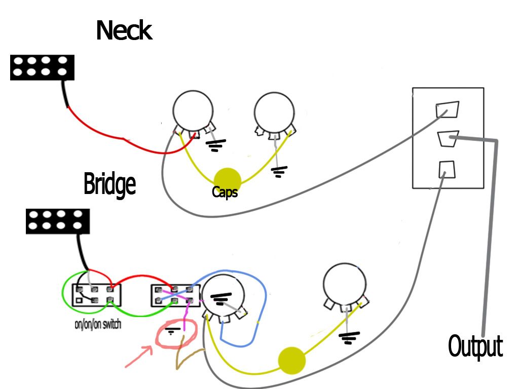 And can I solder the ground wire from the pickup to the case of the 3-way toggle which is metal? Also, when I connect the tone caps does it matter which way/lug I put the + and - ? I'm not sure how to tell, I've heard that when you hold the cap with the letters infront of you the + side is on the left leg...but I don't know if it's universal? |
|
|
|
Post by newey on Apr 3, 2013 21:51:15 GMT -5
Only electrolytic capacitors have a "+" and a "-". There is no need to use electrolytic caps, and they aren't usually seen in values that one would typically have in a tone control. If you do have electrolytic caps, the negative lead is shorter than the positive one. Non-electrolytic caps can be mounted either way around, it doesn't matter. These are the vast majority of caps that one would see advertised for guitar use. Maybe you'd better more fully describe what cap(s) you are using . . .  And: I'm not clear on what you're saying here, but the area you have circled on the diagram makes it look like you want to ground the "hot" side of the volume pot (i.e., the gray wire going from the V pot to the toggle switch.) If that's what you mean, no, don't do that. The fuchsia wire from the P/P lower right-hand lug (as per the diagram) is connected to ground. We originally showed it grounded to the P/P pot, but if you're grounding elsewhere as we discussed, you'll need to run some wire to the grounding point. Your diagram omits several grounds (like the pickup - leads, the string ground, the shield wires). There may be a frame ground for the 3-way toggle as well, also not shown. And, the output jack negative is not shown. That's all OK, those grounds are often omitted from diagrams for clarity. They're understood to be needed, but not shown. But (unless you're talking about an unseen frame ground) none of the wires shown on your diagram which are going to the 3-way switch should be grounded. |
|
|
|
Post by silencer006 on Apr 4, 2013 9:20:50 GMT -5
Thanks newey. I think I should be ok with the caps then. I picked these up at the music store, though they were out of the ones I wanted these were better than nothing. They were from fender and .047uf. Brown ones with legs of same size. Regarding my grounding question: I thought about it more after I had posted. I usually get in a rush it seems and leave out vital info. Forgive me for that, I just want to be done...haha. I am having fun learning still though. The wire I was talking about is one that's from the original wiring I saved. The case (or rubber) is green and it has 1 white wire in it (hot) and one ground wire (bare). I didn't add it to my diagram earlier cause I thought I was gonna be able to handle it lol So, the wire goes from the 3 way toggle switch to the v. pot. And it does have a ground wire rolled together in it's case and its grounded on the side of the 3 way toggle switch's box. So, I understand since it's grounded there, wouldn't it be OK to connect the ground from the dpdt switch (fushia color) and thus making the whole thing ground at the toggle box? Hope that makes sense. Is it common that the wires that go from the v.pots lug to the 3 way toggle have grounds themselves? none of the wires shown on your diagram which are going to the 3-way switch should be grounded. Hmm, is that what you mean then? That the wires from the v. pot to the 3 way toggle shouldn't need a ground wire rolled up in the wire woth the hot like mine is? |
|
|
|
Post by newey on Apr 4, 2013 11:44:05 GMT -5
Grounding the frame of the toggle switch is often done. It's not usually critical to do so to reduce noise, but it might be helpful in some circumstances. It certainly won't hurt anything to ground it. Whether the ground wire runs through the same insulation as the signal-carrying wire from the V pot to the switch is irrelevant. But it is not enough to simply connect the frame ground wire to the ground wire from the P/P switch- both of those points, in turn, need to be grounded, not just connected together. Whether you use the back of a pot, or as suggested, a washer or a lug to some other point, you need to have a point at which all grounds are collected, and tied together. This point, in turn, must be connected to the "sleeve" of the output jack (which then finds ground through your guitar cable, to the ground side of your amp, which then is ultimately grounded through your electrical mains). This is what makes a complete circuit. Without it, electrical current doesn't flow, meaning no sound from your pickups. So, your grounding point must collect all of the following wires: - The wire from your output jack sleeve (AKA "barrel")
- The bridge/string ground wire
- The "negative" wire from neck pickup (the bridge negative goes to ground through the mode and phase switches, as shown on your diagram.)
- If present, the bare wire shields from your two pickups
- If you have shielded your cavity or pickguard, a connection from those points.
- any frame grounds for your pots and switches, and
- Every point on your diagram where a ground symbol appears.
Now, please also understand that you don't necessarily have a separate wire for each of these things. For example, ash suggested that a washer over the shaft of one of the pots can be used as a grounding point. This will then ground the pot frame by contact, as well as grounding any shielding on the pickguard by contact. You can also "daisy-chain" the various frame grounds for pots and switches together, you need not run a separate wire for each one. What is important is that somehow each of those points ultimately connects to the output jack sleeve. Also note that, when we use terms like "ground", "hot", "positive" and "negative", these are really misnomers, because a guitar circuit is an AC circuit, not DC. "Ground" and "hot" are both just convenient shorthand terms. As ash noted above, for example, when you have a phase switch, "ground" and "hot" swap positions, and the labels become meaningless. To be technically accurate, we should speak of "signal send" instead of "hot", and "signal return" instead of ground. With pickups, the terminology used is often "start" and "finish". Such terms indicate that denominations are always relative in an AC circuit, not absolutes as in DC. But it's just easier to speak of these things using words like "ground", so long as we all understand that these are not absolutes in a guitar circuit (in a DC circuit, like the innards of a stompbox, the terms are absolute, and "hot" and "ground" cannot be interchanged). |
|
|
|
Post by silencer006 on Apr 4, 2013 11:51:00 GMT -5
Ah, thanks for clearing that up. So, is it ok for me to assume (i know it might be difficult without seeing it yourself but) that the way it's wired now:
The cable that goes from the 3way toggle and out to the output jack where it is grounded to the sleeve by original wiring, that I could ground my other loose grounds to the same spot, i.e the 3way toggle case? Since that is where ultimately the ground that goes to the output is.
|
|
|
|
Post by newey on Apr 4, 2013 12:14:01 GMT -5
If the output jack sleeve is grounded to the frame of the switch, then yes, you can use that point, if you have enough room to get all the wires onto there.
Just be sure that nothing contacts the wire from the center lug of the switch to the tip of the jack, since it sounds like the two wires run together.
|
|
|
|
Post by ashcatlt on Apr 4, 2013 16:01:16 GMT -5
But it's just easier to speak of these things using words like "ground", so long as we all understand that these are not absolutes in a guitar circuit (in a DC circuit, like the innards of a stompbox, the terms are absolute, and "hot" and "ground" cannot be interchanged). This is getting a bit beyond what the OP is looking for, but since you went there... I'm not completely comfortable with what you've said here. The difference between DC and AC is that with DC one wire is always more positive than the other. Either (or neither) of these may be used as ground, depending on the needs of of the circuit. "Ground" is really a term we use for a reference voltage, or a common node in a circuit. Doesn't really matter whether that circuit is AC or DC. We normally think of "hot" as being more positive than "ground", but this is not always the case. There are a number of pedal designs where everything is referenced to the "top" of the battery - the +9VDC node of the circuit - and are called "positive ground" circuits. Some are bipolar - for example +/- 9VDC supply with ground halfway between (at 0V). In fact, most active circuits need to be bipolar in order to work on the entire AC waveform so even when using a "single supply" 0V - 9VDC the audio signal will be biased (referenced) to some voltage halfway between the the two extremes of the battery. This is often called Vref - meaning "reference voltage" - but is nearly as often called "audio ground". |
|
|
|
Post by newey on Apr 4, 2013 19:33:17 GMT -5
No, ash, you're right to correct any mis-impressions I have made. And, yes, well beyond the topic here anyway, but we want to be correct nonetheless.
|
|
|
|
Post by silencer006 on Apr 7, 2013 7:10:18 GMT -5
Hey guys! Had to take a few days for some personal stuff but I finished everything on the guitar now.
It does sound good but there is a grounding problem somewhere. I'm gonna borrow a multimeter from my friend this week but I wonder....there is no great buzz or hum except for when I touch the newly installed toggle (on-switch). Is it safe to assume the grounding issue is withing that part, or could it be anywhere?
|
|
|
|
Post by JohnH on Apr 7, 2013 7:53:34 GMT -5
Is the toggle switch with a metal lever and have you tried grounding the body of it? It might help - just try it externally with a bit of wire first to find out - it should help.
|
|
|
|
Post by silencer006 on Apr 8, 2013 16:43:19 GMT -5
Hey guys. Just wanted to drop in and say that I'm finished (for now). The guitar is just buzzing a small amount but not when you touch metal (except the little switch still) but it's nothing I can't live with for the moment as I'm looking into putting a new pup in the neck sometime soon and then I'll go at it again! lol
I wanted to say thanks for helping me out. The guitar sounds great! I'm really happy to have learned about the 50s wiring as mentioned by dewey. I think it cleaned my old stock neck bucker up nicely!
So again, thanks. I'll be around lurking here. And I got more questions about other stuff too but for now I'm taking a break! haha...
Rock on!
|
|