nikogo
Meter Reader 1st Class
   Passerby
Posts: 51 
Likes: 0
|
Post by nikogo on Apr 12, 2015 17:16:17 GMT -5
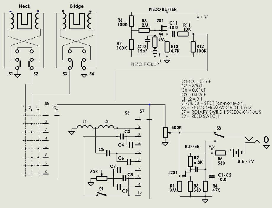
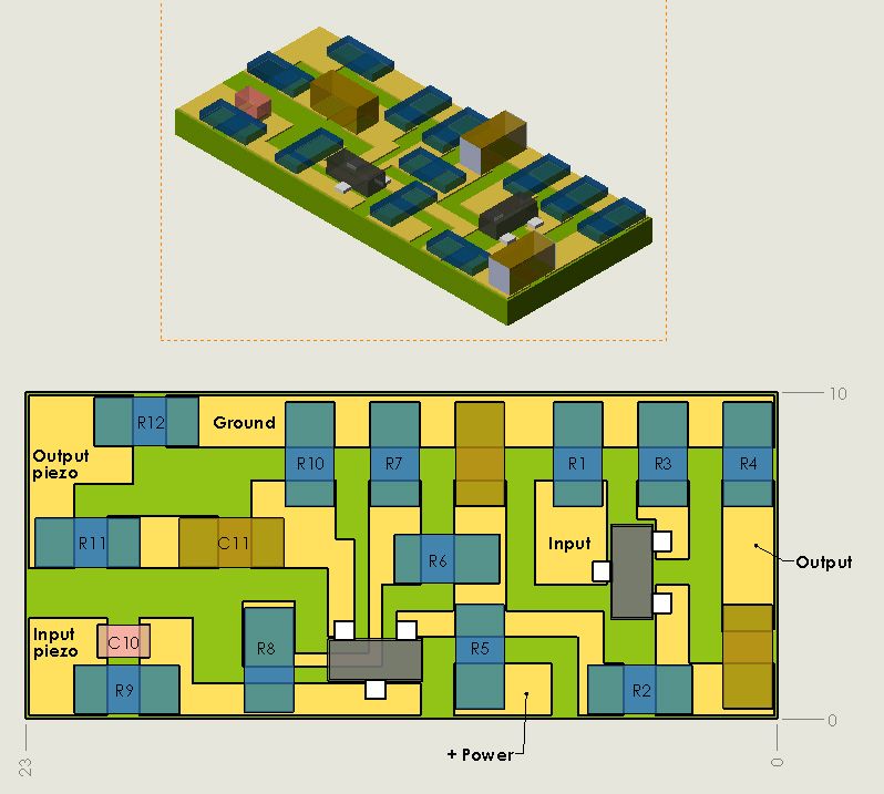
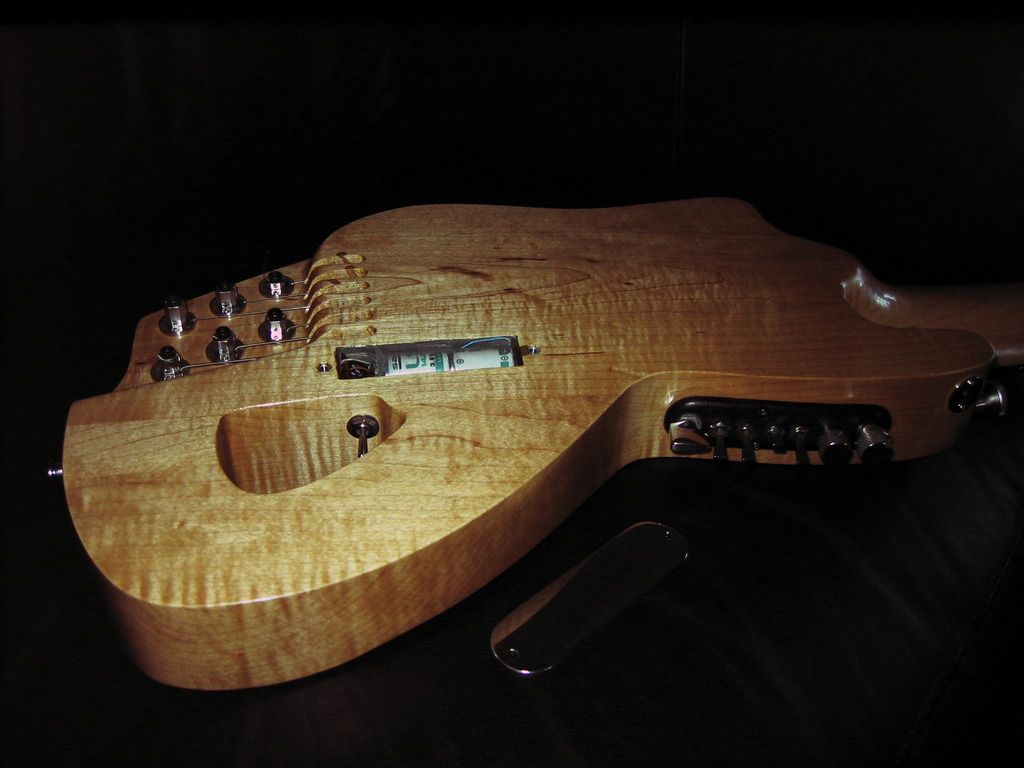
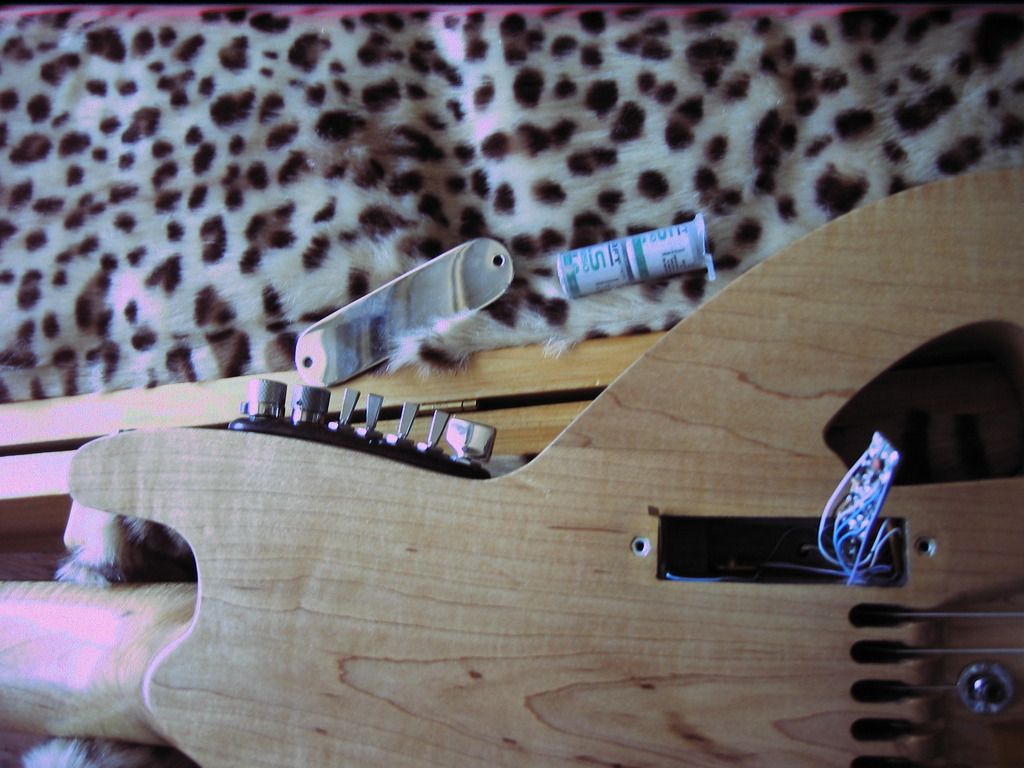
The following scheme is a compromise between desired switching combinations and minimization of control units.  We have two humbuckers and a single, more precisely a piezo bridge pickup. For example L. R. Baggs X-Bridge. The main difference between this scheme and the scheme: guitarnuts2.proboards.com/thread/7439/400-fixed-tones-hhis the pickup selector S5. Here is shown a mechanical rotary encoder - a tiny 8 position device that provides all possible combinations for 3 pickups in binary sequence. Switches S1 and S2 give 4 combinations for the neck HB: parallel, 1 and 2 single coil, series. Switches S3 and S4 do the same for the bridge HB. Selector S5 connects: - 1 - neck HB - 2 - bridge HB - 3 - neck + bridge HB - 4 - X-bridge - 5 - neck HB + X-bridge - 6 - bridge HB + X-bridge - 7 - neck HB + bridge HB + X-bridge - 8 - none. The piezo pickup is connected through a buffer on a follower J201 with high input impedance 5 M that allows to pick deep bass with x-bridge. The input divider is used to adjust the high signal from piezo pickup to the (not enough) high output humbuckers (for example: Dimarzio Steve's special). The capacitor C10 is compensating loss of trebles in divider. The rest in the same as in previous scheme. The PCB layout is here:  The way I placed bufers in my guitar is here: (sorry for poor pictures)   Controls on the last picture are on the top side. From left to right: - rotary filter selector; - treble cut filter potentiometer; - S1,S2, S3, S4; - pickup selector S5. Here only parallel combinations are used between pickups. |
|