|
|
Post by cynical1 on Jul 28, 2016 16:57:45 GMT -5
The kind of thing that might work with the PTB concept is if you could condense the inpedendent volume pots for each of the 3 pickups down into just two channels, one each for say, B/M or N. Then each has its own PTB system either on a dual-ganged or dual-concentric pot This has got to be a bass player thing, but without the two volume controls for what is now the two Peavey pickups, along with independent control of the tone of said pickups...the bass loses 100% of its appeal.   Right now I'm seriously thinking about making this thing a dual output bass. Hell, that's all Billy Sheehan did, and he got the idea from Tim Bogert... This eliminates the need for a switch...bass players hate switches, anyway...and leaves everything to the volume controls. A pickup comes in or out based on blending versus a switch. I can always recombine the signal outside of the bass. It's not like I don't have enough cables for the job...and I've been thinking about doing one for a project, so why not take a project you already have sitting around... As I see it, that's the only way to preserve all the functionality of the existing Peavey pickups and still have the PTB circuit tied into the p-bass pickup that needs it most. I am open to other any other suggestions, though. Happy Trails - Cynical One
EDIT: So, it seemed like a better idea than anything else I could think of, so I redrew it. Again, I'm still not certain I have the reverse audio pot correctly wired. 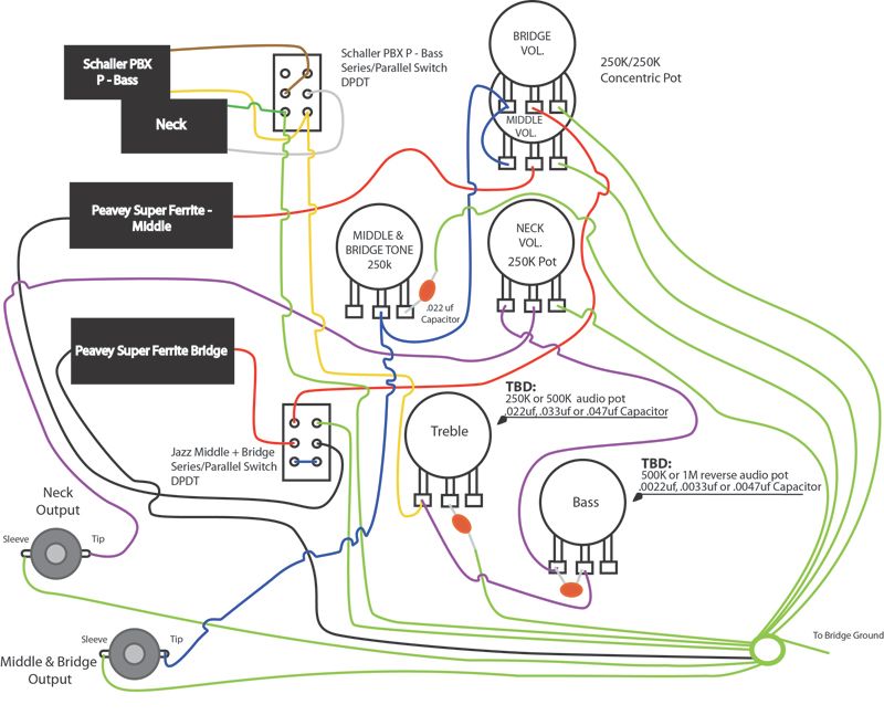 Comments welcomed. Happy Trails Again - Cynical One
EDIT DUEX: Guess I probably should have looked at this earlier, but I just noticed that Peavey wired this bass out of phase...and it seems deliberate: 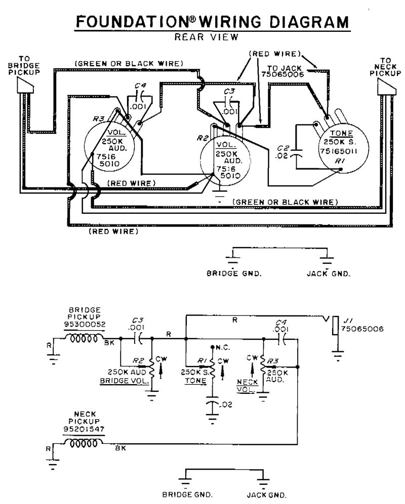 Correct me if I'm wrong, but doesn't the schematic and the assembly drawing conflict? I initially just looked at the bridge pot to get the hot color, but on closer inspection, my bass is backwards of the assembly drawing, in that BLACK carries the signal and RED goes to ground for the neck, and the bridge has RED carrying the signal and BLACK going to ground. Same same, I realize that, but WTF? I looked around and found the theory floated that by wiring them out of phase they are humcancelling when combined. Does that make sense to anyone? Should I be mirroring this in my layout as well? Are the small caps on the volume controls just simple treble bleeds? Again, WTF... OK, I'm done, I'll wait for someone to respond before I add to this thing again... Happy Trails Yet Again - Cynical One |
|
|
|
Post by newey on Jul 29, 2016 5:28:37 GMT -5
Yes it does.
That would be my guess. You can do better, though, as JohnH's research has shown. I don't know why John's findings as to treble bleeds wouldn't be equally applicable to a bass.
As far as whether the intent was to wire the pickups out-of-phase, well, I don't know. Perhaps they are set up as a "matched set" of pickups, and the difference in colors signifies that one pickup is also of opposite polarity (RWRP); it would then be hum-cancelling and in-phase. You could, of course, check the phasing with the screwdriver pull-off test to see whether this is the case.
If the pickups aren't of reverse polarity, one to the other, then combining them OOP would be hum-cancelling. But I can't believe that Peavey would specify "Super Ferrite" pickups and then emasculate them by wiring them OOP. Particularly on a bass, where the usual plan is for more low-end grunt, not less.
|
|
|
|
Post by JohnH on Jul 29, 2016 5:58:27 GMT -5
The new diagram looks fine to me, except the PBass PTB treble control appears to be using the wrong outer lug. It should the same as the other treble control.
For values, I had a play around and I'll put uo some graphs tommorrow. But first impression was a 1M bass pot with 3.3nF cap, to give maximum bass range without cutting too much into the mids. But Ill chart some options since you should make the choice. In the thread I posted about PTB, I see I already plotted down to bass low E, so it will be much like that but based on parameters for a bass pickup.
|
|
|
|
Post by cynical1 on Jul 29, 2016 10:47:47 GMT -5
As far as whether the intent was to wire the pickups out-of-phase, well, I don't know. Perhaps they are set up as a "matched set" of pickups, and the difference in colors signifies that one pickup is also of opposite polarity (RWRP); it would then be hum-cancelling and in-phase. You could, of course, check the phasing with the screwdriver pull-off test to see whether this is the case. Yeah, that's on the list once I get it apart. Considering I'm one usually railing at OEMs for taking the least expensive way out, I don't know why I was so surprised at finding this yesterday. If you're putting this pickup in multiple models, why manufacture two different pickups when all you have to do is wire them OOP to achieve a humbucking pair. I guess that explains why this bass always sounded testicularly deficient on the low end. I could never figure it out, as you can feel the strings vibrate distinctly when playing unplugged...normally a good sign. I love the tone of this bass above the 5th fret. It always had a certain sing to it. I guess I'll re-wire it OOP to preserve what I like above the 5th fret and to keep it humbucking. With the p-bass pickup in the mix now it should round out the low end sufficiently to make this a pretty versatile instrument. One more change to the drawing... The new diagram looks fine to me, except the PBass PTB treble control appears to be using the wrong outer lug. It should the same as the other treble control. Is it just the yellow wire in from the pickup that moves to the right lug, along with the wire out to the bass cut, leaving the capacitor on the middle lug? Or, does it mirror the one for the M & B? Sorry for the stupid question, but I've been pulling this off of assembly diagrams on Google since I can't read a schematic to save the rest of my hair...and we all know what an accurate and reliable source of information the Internet can be... I've looked at your graphs in the PTB posts. I wish I understood this better and could actually use your Guitar Freak tool. Sadly, I learned pnuematics and hydraulics before I started trying to understand electricity. ChrisK always felt they were the same, but I'm here to tell you, applying electrical concepts in the same manner you would pnuematics will make all the magic smoke disappear from your electronic components in a skinny minute...blazing fires optional... Thanks again for sticking with me on this one, guys. Happy Trails Cynical One |
|
|
|
Post by JohnH on Jul 29, 2016 16:04:30 GMT -5
Both of those fixes to the PTB treble control are fine. The important thing is that the correct lugs are used on the pot, ie the centre and right lugs as drawn (so need to make a change on the PTB here). But given that is made correct, it doesn't matter which way round those two lugs are used, ie, it makes no difference if the cap comes from the centre or the right. Both your treble controls show the cap other ends to ground, which is normal. But tonally, you can also connect the pot to ground and the cap towards hot. ie, in a series-wired circuit of cap and variable resistor, such as a simple treble control, it makes no difference at all which order they are or which way round they are. OK, There may possible be a tiny theoretical advantage in terms of shielding if the cap goes to ground, as you have it, but negligible. So here are some bass cut plots. These are based on 1M bass cut and 250k volume:  Looking again at them, I think maybe 4.7nF might be good? I'm thinking youd want maximum variation in the low end combined with minimal messing with mids and highs. For bass cut pot values, consider this, which shows 4.7nF with the bass cut varying from 0, to 50k, 100k, 500k and 1M:  Assuming you get either a log or an antilog pot and wire appropriately, then the 50k and 100k plots represent half turn on a 500k or 1M pot respectively. I think the 1M is the go, because not only does it do a bit more at max cut, but at 5 on the knob it has achieved more compared to at 10. At 10, all values of bass cut are completely non-effective, so nothing is lost there. Last point, on treble cut values. The treble cut cap does nothing at max treble, so pick a value that you like for reduced treble, and I don't know what sounds best on a bass. I can run more plots if anted. But, for the treble pot, note that the plots above all use a no-load treble pot at max. If you want to keep it bright and snappy at max, id suggest that. With a normal 250k treble pot in circuit, the plots are all unchanged relative to the lows, but the treble peak is completely flattened. At the top frequency, the true harmonic response of the instrument is falling away much faster than is shown by these plots (which only represent electrical effects), so keeping that treble peak is a good thing if you want to extend the response. If you don't want a no load pot, then Id suggest 500k. |
|
|
|
Post by JohnH on Jul 29, 2016 17:05:59 GMT -5
Here's some more, to illustrate the point about the treble pot value: Here are plots of the electrical response at max treble on either a standard 250k treble pot, or a no-load. Then, the same thing, also taking into account string harmonics, pickup placement(25th fret on a 34" scale), plucking position (6" from bridge), fretting position (fret 3):  Also shown (red), is a bass cut 1M turned down half way to 5, this time with a 3.3nf cap. It looks quite nice as a way to reduce the low end mud? Maybe 3.3nF is a good value? |
|
|
|
Post by cynical1 on Jul 30, 2016 13:17:28 GMT -5
John, you and your GuitarFreak are life savers. I honestly can't thank you enough for these graphs. Remember, I'm one of the people out there that still believes in the "magic smoke" of electronic components...because I've seen so much of it... I'm not 100% certain how this PTB circuit works, but the graphs you posted make it very easy to empirically determine what parts go where.
I found a 1MC pot on Mouser, so that change is in the bag. I agree completely that the 3.3nf capacitor is the best choice to go with it.
Oddly enough, I've always put larger capacitors on guitars than I did basses. For me, I've always liked the .022uf cap. on a bass. One question, though...what a surprise... If raising the pot value on the Bass side from 500K to 1M made such a vast improvement, is there any advantage in going to a 500K no-load pot over the 250K no-load?
I've updated the drawing to show the wire lug changes on the Treble side of the PTB and updated the phase on the Peavey pickups in the drawing. Still wondering if it wouldn't be best to just replicate the 500k\1M original design. I mean, look how far off the 500K pot I had in there originally would have been.
I have to say, if this works like I'm hoping it works, I'll never buy another 4 string bass again...well...
Happy Trails -
Cynical One
|
|
|
|
Post by JohnH on Jul 30, 2016 16:25:45 GMT -5
Great!, I'm glad the plots help. So here are some more. They are based on the option where all the strings and pickups are included, to show the changes in tone in the context of an estimate of the likely real response. This one shows the max treble available with different pot combinations, bass cut is off:  The 500k 500k options for bass and treble is the same as 250k volume plus no-load tone. But if you roll down volume, the 250k volume keeps more consistent tone (not shown here), even if treble bleed is added (optional if needed, 1nF and 150k in parallel on a 500k pot, or 120k if a 250k plot). also, if you look at the step between the red and pale blue lines above, that is the step that happens when a 250k no-load cuts off, and its about 4db. Not huge, but noticeable. With a 500k no load, the step would be halved, but the change of tone as you roll down tone would be different - personal taste. But with a 500k volume, the bass cut circuit changes, and the 3.3nF should be lower, say araound 2.2nF, and the overall bass range with a 1M bass pot is less:  options options.... |
|
|
|
Post by cynical1 on Jul 30, 2016 22:08:19 GMT -5
Crafty throwing more options out there... It looks to me, if I follow all of this correctly, coming from the p-bass pickup, into a 250K No-Load Treble pot, then into a 1M reverse audio pot with 3.3nf capacitor and finally into a 250K Volume linear volume pot is the way to go. Weighing everything evenly I think that answers all the questions I had on the PTB circuit. I've updated the drawing to show the PTB changes, as well as changing the phase wiring on the Peavey pickups. Please feel free to point out any hairs still lingering...or self-inflicted. 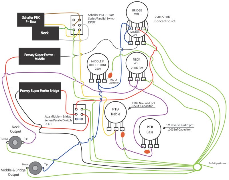 Thanks again, John. Happy Trails Cynical One |
|
|
|
Post by JohnH on Jul 30, 2016 22:39:23 GMT -5
That all looks good, and I agree that those values look likely to be the 'sweet spot' in this case.
|
|
|
|
Post by cynical1 on Jul 31, 2016 15:51:38 GMT -5
I know where I ended up had nothing to do with where I started out, but hey, Gumbo never showed up, so I had to derail it myself...
John, I remember reading your post on the PTB circuit when you first posted it, but not seeing that I had an application for it I just forgot about it. I knew The Peavey always needed more low end, but I didn't want to turn it into a dredge bucket by just slapping another pickup in so close to the neck. I've thought about all kinds of different ways to make adding the third pickup to this bass as an enhancement rather than a gimmick. I'm glad someone out there was paying attention...
After you first suggested the PTB circuit I scoured YouTube looking for examples. Remember, you're talking about a bass cut feature...to a bass player... After about an hour I saw that this was the way to go. The more I think about the dual output...things like running to different amps or effects chains...man...If you ever get to the Pacific Northwest I owe you the beverage of your choice, John...and I need to look for a 4x12 cabinet...
As you old timers here know, I still struggle with electronics in general. I can refret a neck in my sleep, but when you threw this PTB circuit in front of me I was as clueless as George Bush at a press conference. I owe you guys, again, for sticking with me and educating me.
This bass shows everyone one of it's 28 years. It'll be appearing in posts around here for a little while for the various surgeries and procedures, but the hardest part, for me, is done.
Again, that's why I love this place.
Happy Trails
Cynical One
|
|
|
|
Post by newey on Aug 1, 2016 21:31:48 GMT -5
That alone was worth the price of admission, Gumbo derail or not . . .
|
|