|
|
Post by strat80hm on Sept 19, 2016 22:11:29 GMT -5
Hey Nuts, what s wrong with my voltage divider circuit? 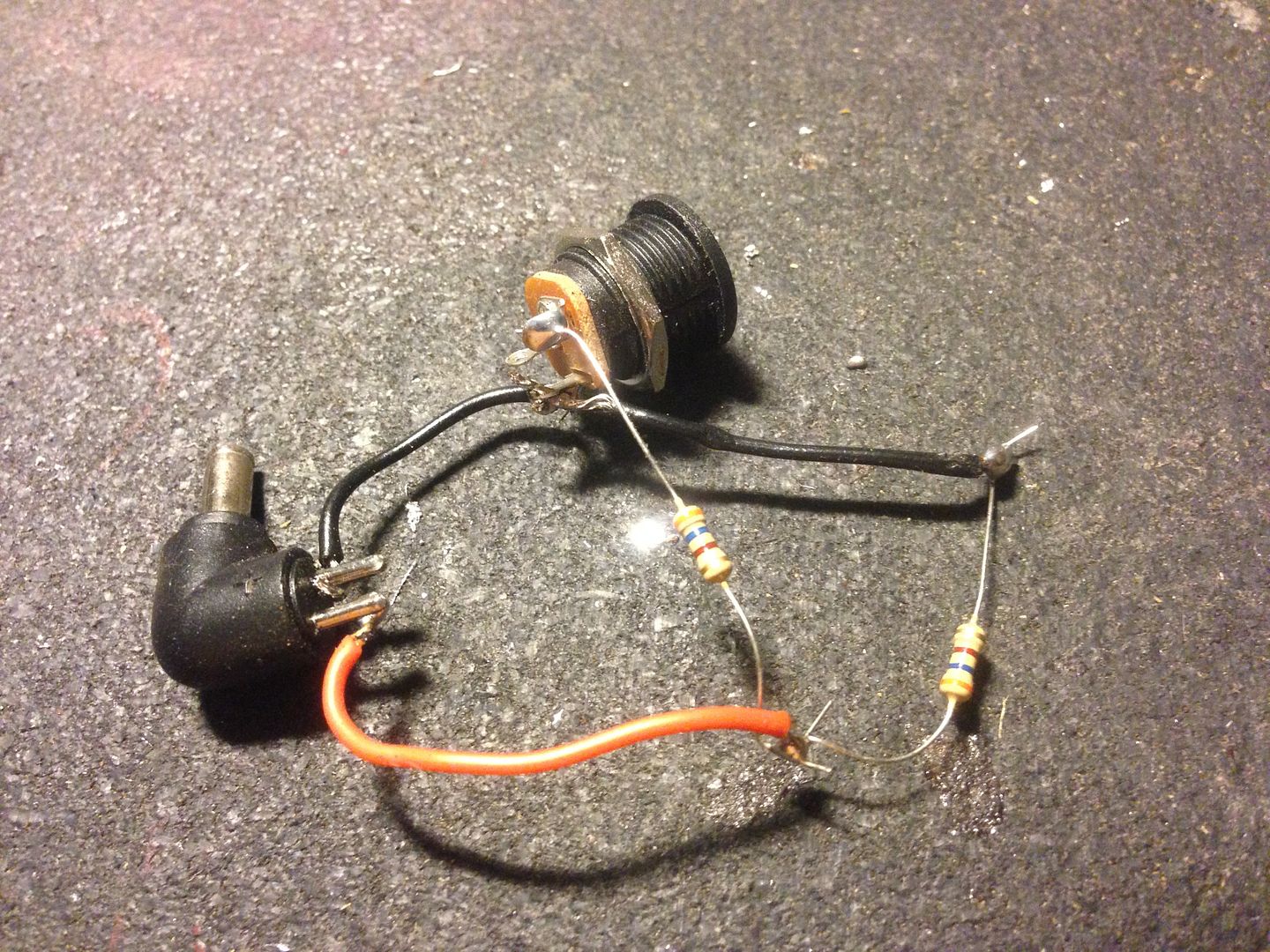 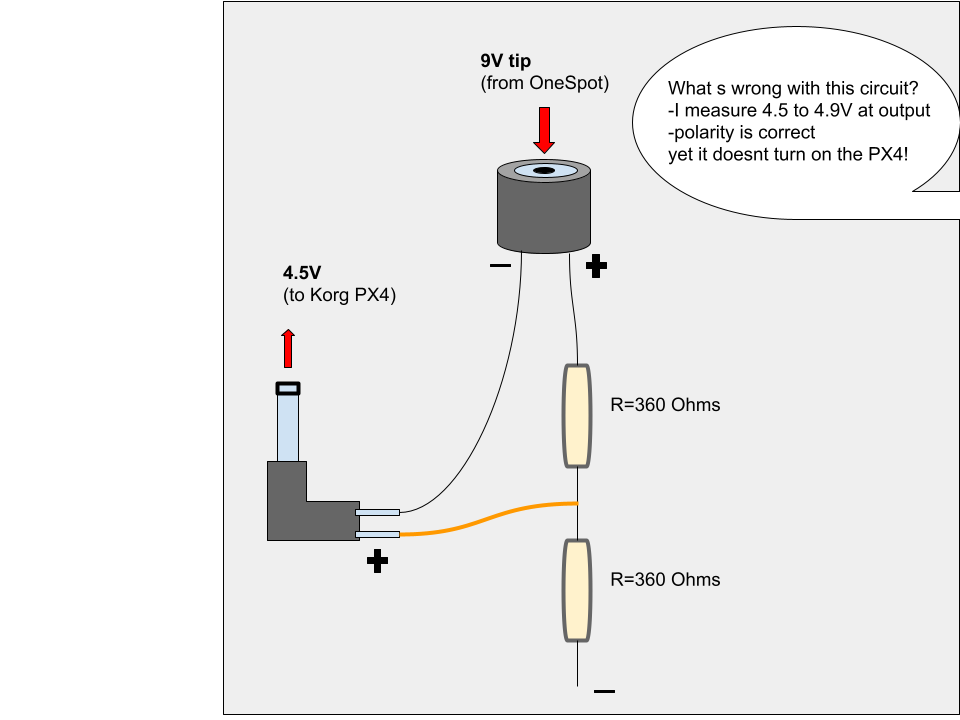 Goal is to use a regular 9V supply (from trusted OneSpot) to feed a (4.5V) Pandora PX4. Note: i use the Pandora as a headphone amplifier (for easy in-ear monitors when playing acoustic guitar on loud stages alongside drums and bass and other noisy toys). It functions perfectly with a 4.5V 500mA charger. This doesnt work, although there s 4.5 to 4.9V at the output and the polarity is right - what could be the issue here? Thanks for your expertise! |
|
col
format tables
Posts: 474
Likes: 25
|
Post by col on Sept 19, 2016 22:57:13 GMT -5
My guess is that it does not work because the resultant current is too low. By using a voltage divider, you are introducing 360 Ohms of resistance. You might just be able to instead just insert a resister in series (no divider) with the power supply. But, get it wrong, and you will blow something or worse. You will have to wait for someone who actually knows what they are talking about here. That's not me!  |
|
|
|
Post by sumgai on Sept 20, 2016 12:18:05 GMT -5
8Oh,
Try this: plug the setup into the PX-4, and then measure the voltage available at the plug prong, whilst all is "live". I'm with col insofar as the resistors are probably limiting the current that gets to your device. More explanation in a moment or two....
Also, make sure that the negative output lead of the OneSpot is truly at the same potential as the Korg's grounded lead... if they aren't, then your voltage reading while disconnected would be 'good', but after connecting (and powering up) would probably be not so good. If your meter supports reading current, then do that too.
Be aware that anytime you divide voltage like this, at half an amp or more, you are effectively shorting the power supply, even if it's several hundred or thousand Ohms of resistance. That's a separate load in parallel with your desired load (the device itself). That causes the power supply to work harder, and brings it closer to the threshold of tripping whatever safety feature it might have had built-in, whether it be a simple fuse/circuit breaker, or something more complicated. (Like perhaps a built-in current limiting capability!) For this reason, you usually see voltage dividers used in circuits that are designed from the beginning to handle that kind of current load.
All in all, this is a nice try, and it's easy to see that the parts can come from a so-called 'junk box' - everyone has one of those, right?  But the better component for your purposes would be a Zener diode. You can find these at most parts outlets, and for (what I call) reasonable prices. 4.5 volts is a common value, so no problem there. I won't go into all the nitty-gritty here, that's beyond what we need to discuss in order to get you up and running. Suffice it to say, Google is your friend. But the better component for your purposes would be a Zener diode. You can find these at most parts outlets, and for (what I call) reasonable prices. 4.5 volts is a common value, so no problem there. I won't go into all the nitty-gritty here, that's beyond what we need to discuss in order to get you up and running. Suffice it to say, Google is your friend. 
BTW, col suggested using a single resistor in series with one of the power leads. Err, not a good idea. Reason being, that becomes only a current limiting device, and any voltage drop will be unnoticible until the resistance value is so high as to make the idea untenable. There are cases where this works, but usually such are found only in micro-current circuitry, and where the resulting voltage does not need to be regulated. Or in really old-timey stuff, built back when electricity was cheaper than snot, space for components was never a problem, and dissipation of the built-up heat was only an afterthought. The wattage values of such resistors was anywhere from 1 to 5 watts, and higher values were not unheard of. (I've got a large handful of them, hooked up as a dummy load for testing amplifiers.) To put that in perspective, an average 1 watt resistor is about the size of half-a-dozen IC's found in many of today's digital amplifiers. And it puts out more heat than all of them together, too! 
When your brain as assimilated all this, report back with any further questions. 
HTH
sumgai
|
|
|
|
Post by strat80hm on Sept 20, 2016 12:27:37 GMT -5
My guess is that it does not work because the resultant current is too low. By using a voltage divider, you are introducing 360 Ohms of resistance. You might just be able to instead just insert a resister in series (no divider) with the power supply. But, get it wrong, and you will blow something or worse. You will have to wait for someone who actually knows what they are talking about here. That's not me!  Thanks for your input Col. I thought it d be something like that: I actually chose 360Ω randomly - also the OneSpot provides 1700mA... |
|
|
|
Post by strat80hm on Sept 20, 2016 13:04:39 GMT -5
8Oh,
Try this: plug the setup into the PX-4, and then measure the voltage available at the plug prong, whilst all is "live". I'm with col insofar as the resistors are probably limiting the current that gets to your device. More explanation in a moment or two....
Also, make sure that the negative output lead of the OneSpot is truly at the same potential as the Korg's grounded lead... if they aren't, then your voltage reading while disconnected would be 'good', but after connecting (and powering up) would probably be not so good. If your meter supports reading current, then do that too.
Thanks Sumgai - will do this and come back with results.. |
|
|
|
Post by reTrEaD on Sept 20, 2016 13:51:05 GMT -5
Hey Nuts, what s wrong with my voltage divider circuit? To begin with, your diagram doesn't match the picture. In the diagram there should be a connection from the bottom of the lower resistor to the negative buss. But since the picture represents reality, we can assume the circuit should function as a voltage divider. You say all the polarities are correct, so let's move on from that. This circuit sets the voltage at the output to 4.5v when there is no additional load other than the resistors. It would be very helpful if we knew how much current the PX4 demands at 4.5v but I can't get any useful results via an internet search. I reckon you might need to wire up some connectors with your 4.5V 500mA charger so you can place an ammeter in series. Barring that, let's imagine what would happen if your PX4 requires a rather modest 100 mA. Then the PX4 would represent the same load as a 90 ohm resistor. The effective parallel combination of the 90 ohm resistor and the lower 360 ohm resistor would be 72 ohms. In series, this would make 432 ohms across the 9v supply. 20.8 mA would flow. 7.5v would be present across the upper 360 ohm resistor. 1.5v would be present across the lower 360 ohm resistor and the PX4.
Not good. And it looks even worse if the PX has higher current demands than our modest estimate. Where do we go from here?I suppose we could design a simple shunt regulator that will never allow the voltage to be greater than 4.5v at the PX4 but if we need to design around a current that is certainly greater than what the PS4 demands, we'll waste a lot of power and generate a considerable amount of heat. We would use a much lower resistance at the top (9 ohm) and a 4.5v zener diode to replace the lower resistor. The zener would dissipate 2.25 watts if there was no external load. Less if there was an external load. The 9 ohm resistor would dissipate 2.25 watts under all circumstances. Things would get a bit warm. Or you could use a three-pin regulator like a 7805. I sincerely believe 5v is well within tolerance for a PX4 or any other commercial device intended to be used with a 4.5v wall wart. They cost about a dollar. They can supply up to 1 amp, but need a heatsink if a considerable amount of current is supplied. I would try one without a heatsink and see if it gets more than warm to the touch under load. If the 5v makes you uncomfortable for some reason, you could just add a silicon diode in series with the PX5. |
|
|
|
Post by strat80hm on Sept 20, 2016 16:44:15 GMT -5
8Oh,
Try this: plug the setup into the PX-4, and then measure the voltage available at the plug prong, whilst all is "live". I'm with col insofar as the resistors are probably limiting the current that gets to your device. More explanation in a moment or two....
If your meter supports reading current, then do that too.
Thanks Sumgai - will do this and come back with results.. I measure 4.6V at plug prong when all plugged Cant seem to measure current properly though - i read [-0.003] DC and it seems the unit is mA (which d makes a very low current right?) How do i do that? (searching on my own but not that obvious..) |
|
|
|
Post by strat80hm on Sept 20, 2016 17:22:16 GMT -5
Hey Nuts, what s wrong with my voltage divider circuit? It would be very helpful if we knew how much current the PX4 demands at 4.5v but I can't get any useful results via an internet search. I reckon you might need to wire up some connectors with your 4.5V 500mA charger so you can place an ammeter in series. Barring that, let's imagine what would happen if your PX4 requires a rather modest 100 mA. 1.5v would be present across the lower 360 ohm resistor and the PX4. Not good. And it looks even worse if the PX has higher current demands than our modest estimate. Where do we go from here?Or you could use a three-pin regulator like a 7805. . Hey Retread, Thanks for your lights! PX4 requires 4.5V via plug (though i measure a 4.9V from power supply, so there s some margin) No mention of mA needs, though original power supply provides 500mA Also accepts 4x15V batteries=6V So you re also saying that the issue must be the current flow? As said above, i cant seem to measure it properly.. yet (learning..) I m trying to create a mini-circuit that could be housed in tube-shrink and hidden under the PX4 on my pedalboard (sharing the same OneSpot power supply), so staying away from heat wouldnt be a bad direction. I like the 7805 suggestion: would it be something like that? 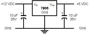 |
|
|
|
Post by sumgai on Sept 20, 2016 20:22:20 GMT -5
8Oh,
Your diagram immediately above is good, but compressing it all into a heat-shrink-tube sized unit will prove unwieldy, to say the least. Better plan on other means of wrapping it all up into a neat package that can hide under the pedals on the board, or you're gonna get a visit from the Environmental Police for the ensuing gunky smoke and stench! (i.e. the tubing will shuffle off this mortal coil, as the parts heat up.)
In essence, any time you "get rid" of voltage (really, we're talking about current, which means flow of electrons), you are obeying the laws of energy conservation - you're trading voltage for heat, via a simple conversion of one to the other. There are no magic bullets that can get away from that, sorry to say, hence my 'advice' about other means to package it up. Remember, current flow is electrons moving from point A to point B, and they don't do that without causing some amount of heat along the way. Such is the way of physics.
reTrEaD lays it all out correctly, something that I wanted to avoid in the event that it might get in your way as you move towards your solution. In terms of trade-off, the regulator will give you a solid voltage (at the necessary current flow), but it can cost more when you factor in the caps, and you really don't want to leave them out. Moreover, unless you buy a physically bigger version, then you will likely need a heat sink, thus adding to the cost, and also increasing your real estate needs.
To my mind, the Zener is your best bet in terms of compromising between size, heat, simplicity and cost. Generally, you need to add only one resistor, and the part's job is to limit what we call the in-rush current - what happens when you first throw the power switch. After that, the part should have no great effect on current flow, hence the design calling for a low resistance value. Again, reTrEaD's short and sweet treatise is spot-on, follow it carefully and you should be good to go. However....
If your power supply puts out 4.9vDC at 500mA (which is not really 500mA of current flow when there's no load!), then it's a good bet that it's unregulated, such that it's probably supplying 4.5 (or your reading, 4.6)vDC at somewhere north of 400mA. It's not a linear equation, so I can't be sure without some exact current measurements, but that's good for a starter. Substitute those numbers for what reTrEaD used in his example, and I think you'll be smiling. 
BTW, it may not be super-obvious, but in order read current on your meter, you don't use the same jack hole for the positive lead. That lead will be inserted into another hole on the meter, usually labeled as A or mA. At the same time, you don't measure across your test points like you do in a voltage reading, you instead break a connection and insert the meter between those two connection points. In essence, voltage readings are in parallel with the part/circuit under test, current readings are in series with the part/circuit under test. Does that make sense to you? 
HTH
sumgai
|
|
|
|
Post by ashcatlt on Sept 21, 2016 12:28:07 GMT -5
I measure 4.6V at plug prong when all plugged !!! But then it's not turning on, so we still don't actually know how much current it wants.  Does this change even momentarily when you try to turn it on? To measure current, your meter must be in series. It shouldn't be much if the thing isn't on and pulling. Are you absolutely sure that it's the right polarity? Edit - though honestly, I think the question is answered. The device itself is in parallel with your "bottom resistor", and being (probably) much smaller, will tend to dominate. So the question then becomes "why not just carry two adapters?" In this case there's no chance of accidentally plugging the wrong one into the wrong hole in either direction. |
|
col
format tables
Posts: 474
Likes: 25
|
Post by col on Sept 21, 2016 16:09:25 GMT -5
You will have to wait for someone who actually knows what they are talking about here. That's not me!  8Oh,
BTW, col suggested using a single resistor in series with one of the power leads. Err, not a good idea. Reason being, that becomes only a current limiting device, and any voltage drop will be unnoticible until the resistance value is so high as to make the idea untenable. There are cases where this works, but usually such are found only in micro-current circuitry, and where the resulting voltage does not need to be regulated. Or in really old-timey stuff, built back when electricity was cheaper than snot, space for components was never a problem, and dissipation of the built-up heat was only an afterthought. The wattage values of such resistors was anywhere from 1 to 5 watts, and higher values were not unheard of. (I've got a large handful of them, hooked up as a dummy load for testing amplifiers.) To put that in perspective, an average 1 watt resistor is about the size of half-a-dozen IC's found in many of today's digital amplifiers. And it puts out more heat than all of them together, too! 
When your brain as assimilated all this, report back with any further questions. 
HTH
sumgai You see, strat80hm, I was right!  |
|
|
|
Post by cynical1 on Sept 21, 2016 18:09:19 GMT -5
You see...I was right!  Words David Cameron hopes to use in a sentence one day... HTC1 |
|
|
|
Post by strat80hm on Sept 22, 2016 20:18:05 GMT -5
Your diagram immediately above is good, but compressing it all into a heat-shrink-tube sized unit will prove unwieldy, to say the least. Better plan on other means of wrapping it all up into a neat package that can hide under the pedals on the board, or you're gonna get a visit from the Environmental Police for the ensuing gunky smoke and stench! (i.e. the tubing will shuffle off this mortal coil, as the parts heat up.)
The regulator will give you a solid voltage (at the necessary current flow), but it can cost more when you factor in the caps, and you really don't want to leave them out. Moreover, unless you buy a physically bigger version, then you will likely need a heat sink, thus adding to the cost, and also increasing your real estate needs.
So the regulator is an option - albeit a lil pricey and bulkier (i m a total novice - the whole circuit will look like something quite compact anyway that d fit into the proverbial Altoid tin right? (the device (PX4) is 1/3 smaller than an iphone, could maybe stack em up neatly if not too hot..) Thanks, will look into that..
Unfortunately not smiling yet - not getting the humor since the modest remaining of my distant physic classes are long gone after all these years of life (booze and pot might have helped in the erasing process i imagine.. but i digress) - do you mean that this is likely to function?? 
Thanks for this - i guess i sort remember that - although it doesnt really seem to work: i plug the Red probe into "400mA FUSED", then tried to "insert" the multimeter in serie (thanks to convenient alligator clips) between power supply and device 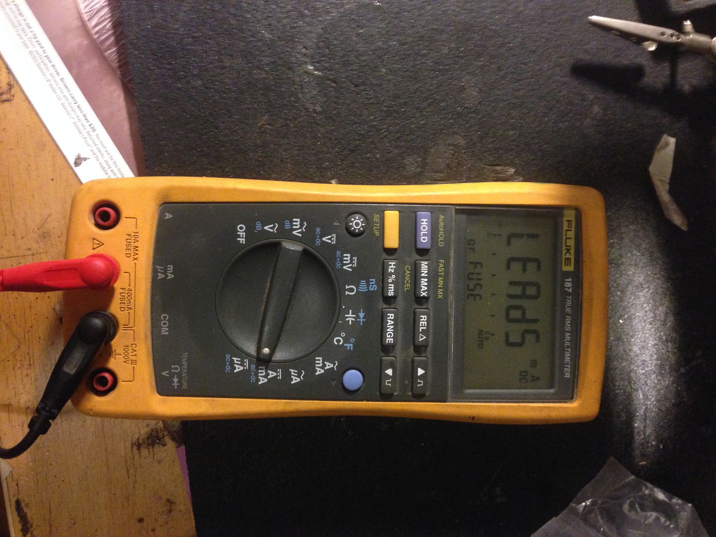 In serie, i can read 0.016mA DC - although then the PX4 doesnt start up. 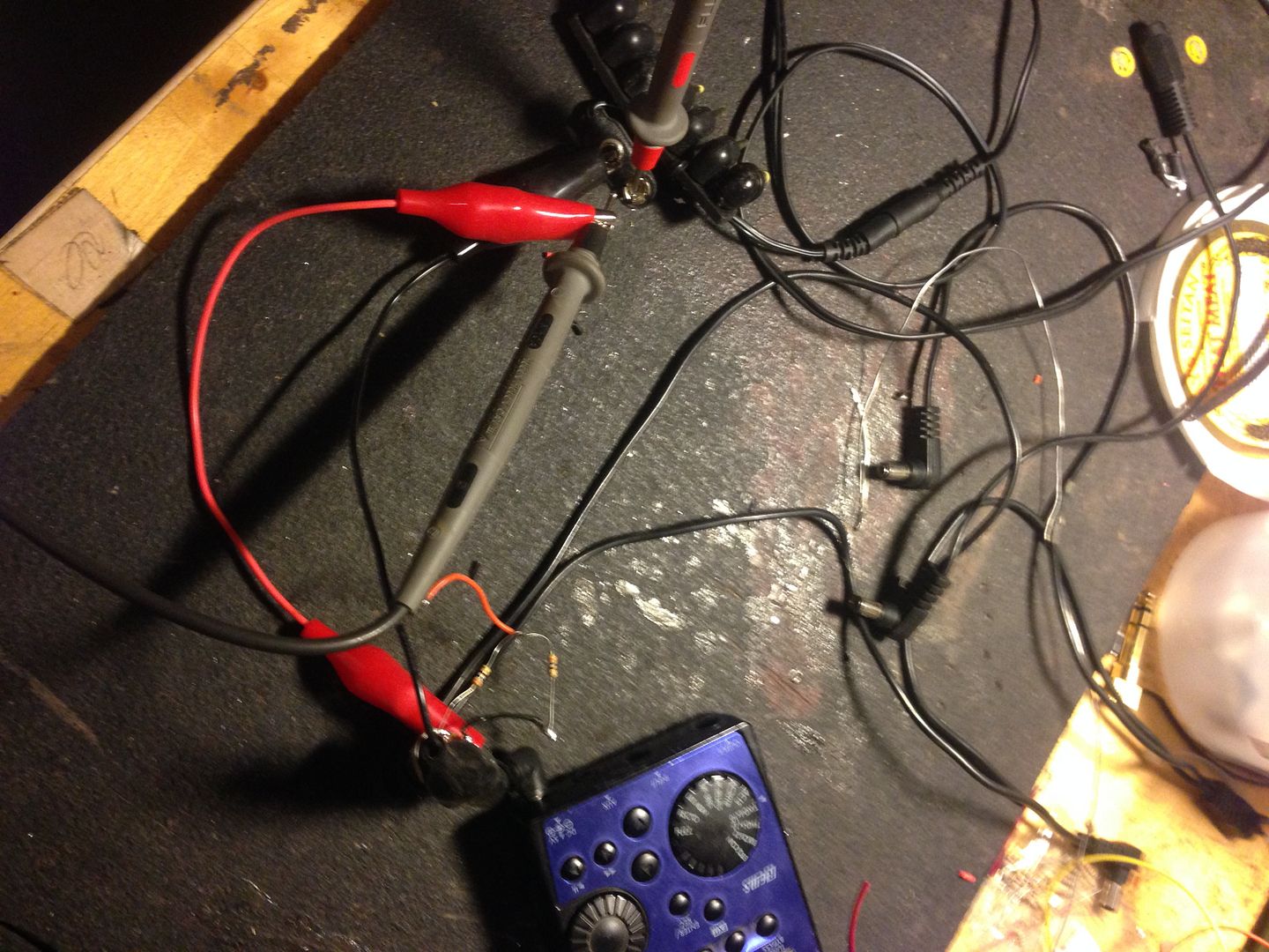 In parallel" i then can read 0.0016A - while the PX4 is on. 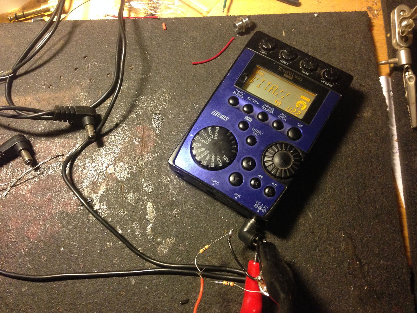 Not sure what i m doing wrong here.. But then it's not turning on, so we still don't actually know how much current it wants.  Does this change even momentarily when you try to turn it on? Not seeing any change wether i turn PX4 on or off. Does this tell you anything? Well the device only turns on in one way, so i assume there s no confusion.. 2 adaptors is what i m using live as of now - it works ok but it s much inconvenient: longer set up time, bulky, extra outlet, double cable, one more thing to forget when you leave home, one more thing to forget when you pack up in the dark before the next band set up..). i guess i am dreaming of some sort of self-sufficient pedalboard/earmonitor package working with 1 OneSpot, 1 jack and 1 headset. Indeed Col! I ll keep on listening to your wisdom Is this about the poor Brexit choice? BTW i cant believe that this dude is in his 40s sometimes.. |
|
|
|
Post by ashcatlt on Sept 23, 2016 11:17:33 GMT -5
Wait! It's on? What's not working then? I wouldn't have thought it would even boot up if it wasn't getting enough power to actually function, but... As for two adapters, I do it all the time myself, but then all my stuffs are on a pedalboard, and the pedal ends of the wallwarts stay plugged in. I usually plug both adapters into one of those brown extension cords so that it only takes up one hole on the power strip. You're not one of those guys who shows up with all of his stuff balled in a shopping bag, plugs it all in from scratch, and has to ask to borrow a power strip are you?  My bassist is one of those guys who prefers to plug his stuff in from scratch every time. Pisses me right off! He can't even remember how it's supposed to go together, so has to reference a picture on his phone every time. The worst part is he's got a Digitech Whammy which wants a 9VAC adapter, and that damn thing fits perfectly in other pedals and will kill them really quick! |
|
|
|
Post by strat80hm on Sept 23, 2016 14:39:36 GMT -5
Wait! It's on? What's not working then? I wouldn't have thought it would even boot up if it wasn't getting enough power to actually function, but... Ok there s a confusion here: i was trying to measure the current comsumption of the PX4, so yes it turns on when i use the 4.5V power supply! Not with the 9V OneSpot yet, which is the mission. Sorry for confusion.. Haha no i m not - i am one of those who spends a lot of time figuring out ways to have the most compact and ergonomic setup possible - everything (guitar, capo, slide, setlist, cables, pedalboard, DIbox, headphones..) is tight together and ready to plug and play as quickly as possible, fast-NYC style. That is why i want my system (pedalboard+earmonitor) to work with just 1 OneSpot.. unsuccessfully so far |
|
|
|
Post by reTrEaD on Sept 24, 2016 1:55:48 GMT -5
So the regulator is an option - albeit a lil pricey and bulkier (i m a total novice - the whole circuit will look like something quite compact anyway that d fit into the proverbial Altoid tin right? A 7805 is quite small. The circuit you posted earlier in the thread is just fine but the capacitors are unnecessarily large. 0.3uF across the input and 0.1uF across the output are the recommended values. Not sure that a dollar or less per unit is pricey. I reckon you could easily fit six or eight completed circuits in an Altoid's tin. If a heatsink was necessary, that would take up the most space. Then you'd only fit two or three in an Altoids tin. Why fear the 7805? It only has one more terminal than a resistor, capacitor, or diode. And it will dissipate less power (generate less heat) than a resistor & zener shunt regulator. |
|
|
|
Post by strat80hm on Sept 24, 2016 14:33:43 GMT -5
Well i do like the idea of a small circuit that fits into a small box - will order a 7805 (unexpensive indeed about 50 cents pop.. plus 10 bucks for shipping!) and will see if the 5V it provides will turn on the PX4 - which so far it didnt with the OneSpot..
|
|
|
|
Post by sumgai on Sept 24, 2016 16:06:05 GMT -5
s8,
A 7805 is good, I was only pointing out trade-off considerations.
Do be aware that 7805s come in many physical sizes, for the reason that they can handle different current levels. In your case, I'd specify one that handles at least 1A, a very common part (read: easy to find, therefore inexpensive). Don't go for the 500mA (or even lower) units, they'll need a heat sink, if your wallwart's specifications are any indication. A 7805 with 1Amp of current carrying capacity should not require an additional heat sink.
HTH
sumgai
|
|
|
|
Post by reTrEaD on Sept 24, 2016 18:13:16 GMT -5
If you're paying ten bucks for shipping you might want to check the details on the shipping costs. If it's a flat rate up to a certain weight, you can amortize the cost over several items.
Perhaps you need some resistors, capacitors, diodes, small-signal FETs, etc for bench stock if you do a lot of experimentation?
Even if not, It might be wise to buy several 7805, 7809, 7812 regulators to keep on hand.
I recommend the TO-220 case.
What country do you live in? In the US, Jameco Electronics might be a cheaper way to buy.
|
|
|
|
Post by strat80hm on Sept 24, 2016 22:17:58 GMT -5
Thanks for recap guys! -7805 at least 1A - TO-220 case (https://en.wikipedia.org/wiki/TO-220) -0.3uF Capacitor at input (cant seem to find that value on website, only 0.22uF or 1uF, which one is good then?) www.jameco.com/z/MD-22-Capacitor-Monolithic-Ceramic-0-22-micro-F-50V-plusmn-20-37-_25540.html-0.1uF at output -heatsink -enclosure (altoid?) -9V input socket - 4.5V output plug Q- do you think that i am gonna need some circuit board or it s manageable as "stand-alone" (i m lacking the jargon, hope this makes sense) I ll give Jameco a try thanks for the tip (shipping free for order above $10) (if NYC is still considered part of the it - nymag.com/nymetro/news/rnc/9573 - then yup, i m in the US) I m a working musician - time spent playing/experimenting with guitar and sounds - but unfortunately i m mostly a clueless-beginner-apprentice when it comes to understanding electronic (beyond pots and pickups and sustainer..) - though i wish i d spend more time around circuits! I ll definitely will purchase some extra (pots, plugs..) - cant seem to find guitar-friendly 250K logarithmic pots neither on Jameco Might have to order from different retailers, damn.. More soon hopefully  |
|
|
|
Post by reTrEaD on Sept 25, 2016 9:28:58 GMT -5
For shipping cost considerations, NYC should be considered in the US. In all other aspects, YMMV.  -0.3uF Capacitor at input (cant seem to find that value on website, only 0.22uF or 1uF, which one is good then?) Given the choice, I'd lean toward the 1uF but I estimate the 0.22uF shouldn't present any problem at all. I would not use an electrolytic capacitor in this application but it doesn't need to be a ceramic. Film/foil or metalized film are also available in smaller sizes. So if you were thinking of buying some stock for tone caps anyway (typical values are in the range from 0.2uF to 0.5uF), any of those should be just fine. The purpose of the caps in this application is to prevent high frequency oscillation. You might experience no problem at all without them but since caps are cheap . . . -heatsink -enclosure (altoid?) If you intend to use a metal altoid tin as an enclosure, you can probably skip the heatsink. Use a machine screw and nut to bolt the 7805 to the tin. This is likely to allow enough heat dissipation. Of course with the screw head protruding from the bottom of the tin, it won't sit flat. So stick-on rubber feet at the corners would be necessary. The mounting tab of the T-220 case is electrically connected to the middle lug of the 7805, which is ground (negative). That works fine in your application. If you were building around a supply that used a positive ground, the sister to the 7805 (7905) would be the correct choice. Q- do you think that i am gonna need some circuit board or it s manageable as "stand-alone" (i m lacking the jargon, hope this makes sense) Circuit boards generally make for a prettier finished product but in this case you have rare few connection points. A circuit board would be overkill. Point-to-point wiring makes the most sense here. |
|
|
|
Post by ashcatlt on Sept 25, 2016 12:19:46 GMT -5
Is this Altoids tin actually going to be smaller and easier to deal with than he second wallwart? I mean, if you really just want to get high off solder fumes, then by all means have at it! I'm just kind of not seeing how what you're going to build is parts+labor better than what you have.
|
|
|
|
Post by strat80hm on Sept 25, 2016 13:20:19 GMT -5
Good points thanks!
About the Altoid tin, that s just an idea - if the circuit (with or without heatsink) can fit into something smaller (?), i ll be more than happy.
What i have is a small and compact pedalboard with a OneSpot + another (flimsy) 4.5V powersupply (with european plug adaptor) that i each time need to plug separately. it s really not convenient - i d love to use just one plug for all the gear! Much more ergonomic and less hassle on stage.
|
|
|
|
Post by newey on Sept 25, 2016 16:54:13 GMT -5
I'm with ashcatlt, I don't see the advantage to a step-down connector here. If the goal is one plug, deal with it at the mains power end of the thing- your two adapters go into a 2-into-1 power plug, with a bit of cord to a single plug. With some judicious wire routing, the whole shebang may even fit under your pedalboard.
I, too, use a OneSpot for my pedal board, and I don't have any equipment that poses your issue, but I have a complete 6-plug computer powerstrip/surge protector mounted under the pedalboard. The only thing that hangs out from the board is the one power cord . . .
|
|
|
|
Post by reTrEaD on Sept 25, 2016 18:29:29 GMT -5
I agree that a power strip with a one-spot and 4.5v wall wart seems a better path but if you're fixed on just the one-spot and a regulator ... Here's a pic that has a 7805 and a couple of 9V batteries. So you can get a rough idea of the physical size of the 7805 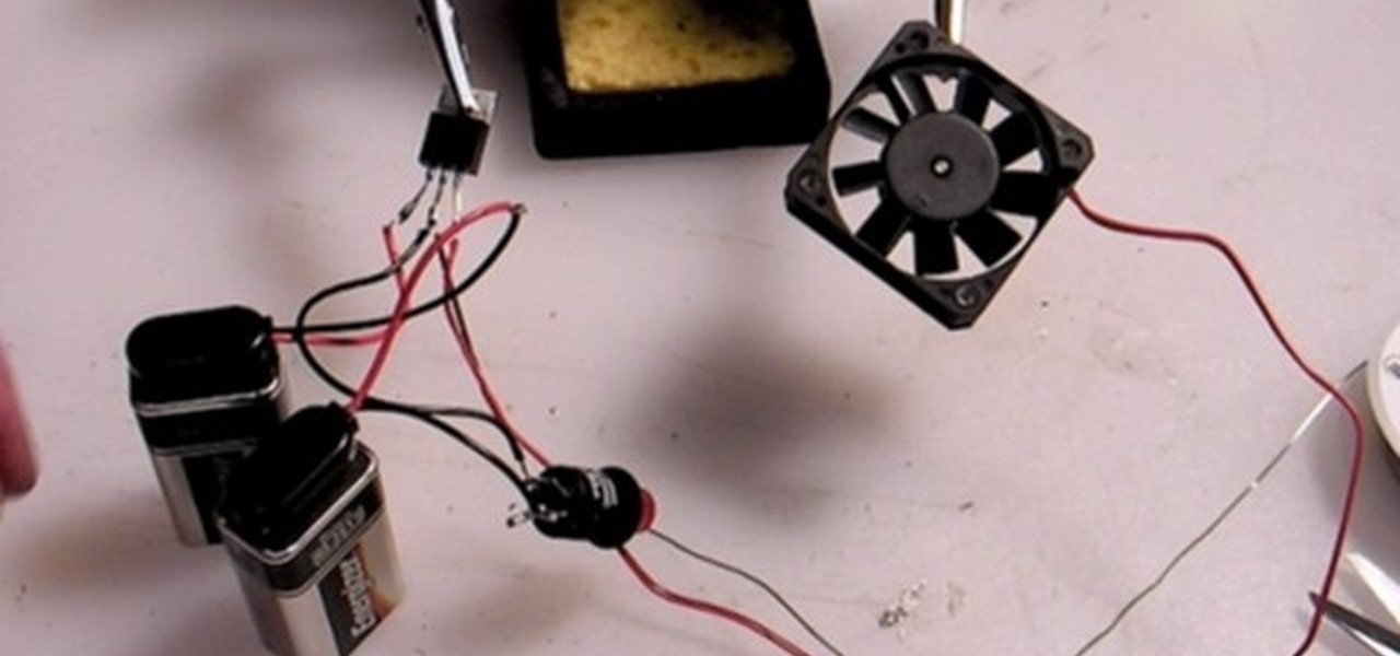 |
|
|
|
Post by sumgai on Sept 26, 2016 12:19:58 GMT -5
Here's another pro-&-con argument to consider:
Pro: In the "two supplies and one mains connection" scenario, we see that if either power supply fails, the remaining gear will continue to operate.
Con: In the "single supply with an additional voltage reducer" scenario, if that single supply goes gunnysack, then everything downline from there becomes null and void. This is what we call a "single point of failure" and Best Design Practices dictate that where we see such a possibility, we do our best to avoid such.
'Nuff said. 
HTH
sumgai
|
|
|
|
Post by strat80hm on Sept 26, 2016 14:21:56 GMT -5
Thanks for insight!
That solution makes total sense overall - however powerstrips are huge!
i have clear limitations: my entire system (pedals+ear monitor system+power supply+cables+DI) must still fit in its bag (a sturdy laptop case with strong shoulder strap and robust handle - much more roadworthy than pedaltrains & co
My homemade pedalboard is light and ergonomic (uses 2 rows and 2 floors), i can access all the 8 switches while pretty much resting my foot on the wah the entire time).
So my whole set up fits this laptop bag + guitar gigbag and it s perfect for commuting around (by bicycle or train) - and is accepted along with the guitar as a carry-on when flying ( just check my clothes, no gear). So i dont have room for any extra charger, thus this thread.
Thanks, looks friendly to me!
I like this sound concept. thanks for the tip Retread - My using a unique 9V OneSpot de facto puts my system into that "single point of failure" situation regardless.
My unique way out when pedalboard fails has been to hastily plug the guitar straight into DI box and keep on smiling - so i ll keep that option up anyway.
I m ordering parts and will give the "unique power supply" a try and see.
Another option would be to find a small pedal that readily accepts 9V while providing a headphone output for monitoring - like the current pedal-sized Korg Pandora actually!
But in general, i like to do with i have, first.
|
|
|
|
Post by strat80hm on Oct 1, 2016 23:02:26 GMT -5
Update: - received the components (Jameco is super fast and pretty cheap indeed) - set up the circuit on breadboard - miracle! PX4 turns on!! Thanks everyone for fine directions! 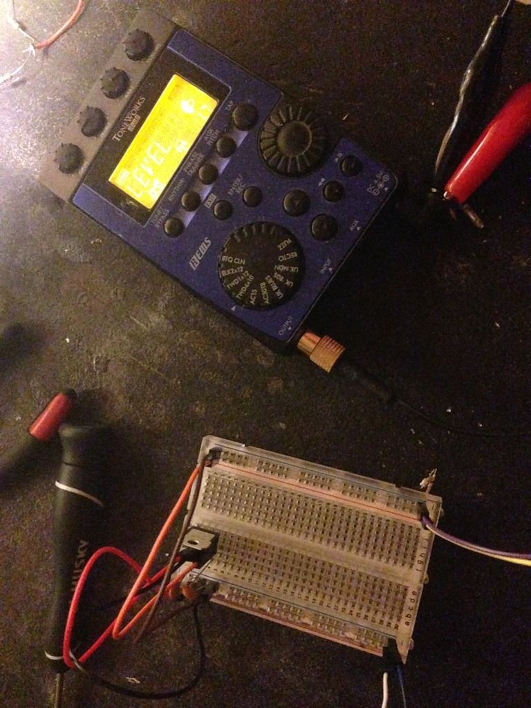 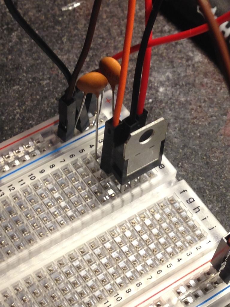 Notes: - i m letting the circuit on to see how it fares over time - the 7805 is indeed getting a bit hot (i still can touch it with my finger though) - i added that little heatsink since - both input and output caps are .1uF (i might have made a mistake ordering..) => is this a concern? is this creating more heat? Now i realize how small that is (good news) so i have to find some small enclosure idea. |
|
|
|
Post by ashcatlt on Oct 2, 2016 12:59:50 GMT -5
Now i realize how small that is (good news) so i have to find some small enclosure idea. Does this thing have a battery compartment? |
|
|
|
Post by strat80hm on Oct 2, 2016 17:15:58 GMT -5
It does actually - large enough for 4 LR6 battery
Are you suggesting to fit it there? that d be neat, although what about the heat?
Actually, after letting it on for a couple of hours, it s not getting really hot, but still a lil - and PX4 is 100% plastic.
Other option would be to hide this circuit inside my home-made switch-looper enclosure.
This is a sturdy plastic electric box that so far contains 2 footswitches, 2 LEDs, 6 quarter-inch jack sockets, 1DC female input => anything that would be incommoded with proximity to circuit?
|
|