|
|
Post by ms on Jan 23, 2017 14:44:01 GMT -5
The first attachment here has the equation describing the effect of eddy currents (from the note I have posted previously) placed on a plot. This plot shows the factor T, which controls the onset of eddy current effects as a function of frequency, for two different values of Rse. Rse is the effective resistance of the material in which the eddy currents flow, but transformed up by the ratio of the coil inductance to the inductance of "secondary", the circuit supporting the eddy currents, such as humbucker slugs. Thus Rse is the value of resistance loading the pickup coil (Lc). k is the coupling constant between the pickup coil and the "secondary". k would be very close to one in a good transformer, but might be .5 in a pickup in a pickup with short open cores and lots of escaping flux. (In the real world Rse increases with frequency because of the skin effect, but the equation describes what happens if it stays constant.)  T controls the process by which the low frequency parameters (Lc and Rc) are transformed into new values as a function of increasing frequency. The effective inductance decreases with frequency, while the losses increase. When Rse = 100,000 ohms, the effect of eddy currents remain very low for a few hundred Hertz, then increases quickly, leveling off at the higher frequencies. When Rse = 1 Meg, the effects have not gotten very large at the top of the audio range, and are small in the effective range that stops at 5KHz for a guitar speaker. These two values are meant to be typical of the range present in real pickups. But how well does the model represent what actually happens? Well, it cannot be perfect, because Rse rises with frequency from the skin effect, and that is very hard to model. We can allow for that to some extent. Rse should continue to increase some instead of leveling out, and the imaginary part of the impedance would not straighten out perfectly. The next attachments show impedance plots for the slug coil from an Japanese PAF clone. (Using just one coil eliminate the coupling between the two coils as a confusing factor.)  The first plot shows the lower and most important frequencies. I have used an external capacitor so that the total is realistic for playing with a cable, and the computer code computes an eddy current factor at the resonant frequency, assuming that the most important frequency at which to evaluate the losses is the resonance. A factor on one would indicate that the losses from the resistance of the coil and eddy currents are equivalent. The green and yellowish lines follow the gray lines very closely for the first few hundred Hz and then deviate as expected. Rse measured at the resonance is about 68K, while K**2 is about .34  The final plot shows the full frequency range with no external C. The green line never levels out and the yellowish line never straightens out as expected with Rse increasing from the skin effect. A later post will show the effects from a single coil alnico pickup. |
|
|
|
Post by ms on Jan 25, 2017 7:36:34 GMT -5
Here is the plot for the tele bridge pickup. Differences from the humbucker coil: 1. The eddy current factor (at the loaded resonance) is under one: more energy is dissipated in the coil resistance than in the eddy currents in the magnets. 2. You can barely see any effect on the inductance. 3. The curve of the real part is just pulling away significantly from the coil resistance. 4. Rse (not on the plot unfortunately) is about 1 Meg. 5. This is the expected results based on the plot of T in the previous post. The eddy current factor is computed in this way (real part at resonance - Rcoil)/Rcoil. The real part of the impedance as a function of frequency is the green line. The dot dash line is the resistance of the coil draw across the whole frequency range for convenience. Thus you can get an approximate value for the eddy current factor from the lines on the plot (and the zero tick mark).  |
|
|
|
Post by antigua on Jan 26, 2017 0:11:00 GMT -5
Thanks for posting this. It looks like it can be very valuable for making generalized models of eddy current losses for simulation purposes. It's hard to find mathematical treatments of eddy current losses on the 'net in general, so this is valuable information. I'm not smart enough to apply this math now, but I hope to be in the near future.
|
|
|
|
Post by ms on Jan 26, 2017 7:14:48 GMT -5
One of the goals of the ongoing effort here (especially JohnH) is to turn a knowledge of the components that make up the impedance of a pickup into a good estimate of its frequency response, allowing the effects of external components to be accounted for as well. There is another approach that seems worth a try, at least along the way. That involves using the impedance measurements themselves, and using component values derived from them only as necessary. It is possible to identify a coil resistance, inductance, and capacitance, but do you need them all in order to compute the frequency response, even with external components? Furthermore, it does not appear to be so easy to model the part of impedance due to eddy currents into the smallest possible number of components. Perhaps taking this other approach will provide some insight. The changing magnetic field from the vibrating string induces a voltage around each turn of the the coil, and since they are all in series, we can model this as one voltage source in series with the inductance. The coil resistance also is in series with the inductance. It is well known that the capacitances between the many bits of wire can be represented as a single capacitor across the coil. So the first three are the series impedance of a voltage divider while the capacitance is the shunt element because the output is also taken across the coil. But what about the impedance due to eddy currents? I tend to think sometimes (incorrectly) that it also goes across the coil like the capacitor since it is like the secondary of a transformer, but this is not right. The effect of eddy currents appears around each turn of the coil just like the signal from the string, and this voltage opposes the build up of current: Lenz's law; there ain't no free lunch.) Thus, this is also goes in the series. So a model based on these ideas looks like this:  So start with the measured impedance; it includes all four of the elements in the above representation. Suppose we find the C value somehow. (It seems practical to do this at the resonance by fitting to a model that incorporates the eddy current effects over a narrow frequency range so that Rse can be assumed constant over that range.) This C can be "unparalleled" leaving an impedance, call it Zu. The real and imaginary parts of this impedance are shown in the impedance plots shown earlier (green and yellowish lines), and the accuracy of the C measurement is shown by the removal of the shape of he peak from Zu. Now Zu and C can be used to make a voltage divider. That is, Zu replaces the three series elements in the above pickup model. Then the frequency response can be directly computed from the impedances of Zu and C. This is the idea I am trying, but it is necessary to measure the frequency response directly in order to check the results. I can do that with the same system used to measure the impedance, modified a bit. |
|
|
|
Post by ms on Jan 26, 2017 7:27:53 GMT -5
Thanks for posting this. It looks like it can be very valuable for making generalized models of eddy current losses for simulation purposes. It's hard to find mathematical treatments of eddy current losses on the 'net in general, so this is valuable information. I'm not smart enough to apply this math now, but I hope to be in the near future. Thanks. I am going to keep going with this with the goal getting the eddy current effects into as simple form as possible. This stuff is not very easy! |
|
|
|
Post by JohnH on Jan 26, 2017 14:23:45 GMT -5
ms - Thanks for your valuable insights and testing. I had similar thoughts about where to put elements that model the eddy damping, and considered both in series with the inductor in the model, (and also part way along the coil, as suggested by Lemme).
and also where I ended up, across the output.
I think it has to be across the output in this kind of model. I agree that the effects are generated in the coil as you note above, but the coil also includes the winding resistance and also particularly it includes the voltage source. I think that only an eddy current element around all of these captures the whole coil and leads to the right response shapes. My mental picture of this is that in truth, we are looking at a poorly coupled transformer with a high turns ratio, and that this transformer load can be transposed into a resistive and inductive load on the main coil, using theory that is apparently well established by those in that field.
I've been working mainly with Antigua's and stratotart's output bode plots, and your impedance plots are the other side of the picture and add extra insight. What would be great would be if we can get both sets of plots from one particular pickup. So far, I can get good matches with the bode plots, and then show that the impedances implied looks very similar to yours, but cant confirm the accuracy of that statement since the tests are from different pickups. As a starter, do you have any pickups available that match to antigua's tests?
If we have a model that gives the right output with different applied loads, and gives the right impedance, then within the accuracy and frequency range that it does so, there is nothing else that needs modelling.
Ive got another question that the impedance plots may be able to sort out. The damping in a model can be all 'real' ie, such as through resistive elements, or it can be partially reactive or 'imaginary' in complex number terms. But it can be a subtle effect, hard to capture. Even a purely resistive load on a coil results in reduction in the slope of apparent inductive reactance as frequency increases. This is not that the inductor is actually changing, but its due to the mathematics of combining resistances and reactances in parallel. Is there any way to confirm the real vs imaginary nature of eddy damping this from tests? I can model each for comparison.
I also looked at skin effects, which could reduce resistive damping with frequency. But these seemed to show that the material thickness at which these would be significant is much greater than is used in pickups, unless you use carbon steel for a pickup cover, which would be a bad idea anyway!
|
|
|
|
Post by ms on Jan 26, 2017 14:59:14 GMT -5
Hi John, I just have time for a quick comment now. The skin effect probably only matters for the cores, but they are important since they are in the coil.
Also I think the eddy current effects seen with the impedance measurement are not all of the effects, most in the case of a hb without a bad cover, but not all. I believe the dip in response with rising frequency seen with some humbuckers is not seen with the impedance measurements, and therefore you need both kinds of measurements (impedance and response) to be able to sort out what all the effects are. This might or might not be right, but I think we can find out.
|
|
|
|
Post by ms on Feb 4, 2017 7:50:11 GMT -5
The major effect of eddy currents on the response of a steel cored pickup is the damping of the pickup resonance. The effect can be greater than the damping from the coil resistance. However, there is another, smaller effect. This is the partial direct cancelation of the varying field from the vibrating string (or test coil) resulting from currents set up in the cores (or other metal). That is: the varying field induces current; the induced current produces a magnetic field; the total of this field and the original field is less than that of the original. (The new field must oppose the buildup of current as Maxwell's equations show, although this opposition is often referred to as Lenz's law, which I describe as "There ain't no free lunch.") Stating this and measuring it are two different things: to measure two things which cause similar effects, we need two different kinds of measurements. These two can be impedance measurements and response measurements. As shown earlier, impedance measurements can be converted to response measurements. However, such response measurements do not show the second effect because there is no exciting magnetic field, just a current. However, response measurements using a current driven coil show both effects. Therefore it should be possible to look at the effect from direct inducement of current by comparing the two measurements as a function of frequency. Therefore I have added response measurements to the setup. The same cross spectrum and data accumulation software is used, but the post processing is different, and of course the hardware setup is different. This is shown in the first attachment:  The output of the Tascom feeds a power amp which provides power to a series resistor driving a small coil with a current sensor resistor to ground. The coil is driven from an impedance much higher than its own to help minimize coupling effects and keep the current reasonably independent of frequency. The exciting signal is similar to the one used in the impedance measurement, Golay complementary sequences, but the signal is digitally low pass filtered before conversion. This is to compensate for the pickup's increasing response with frequency.* (As described in various discussions on this and other forums, the law of magnetic induction describes a process which naturally increases with frequency.) The buffer is a single low noise FET used as a source follower. There is no separate bias resistor; bias is through the pickup coil. Therefore the input resistance of the circuit is about a gazillion ohms. The input capacitance is low because the ~20pf gate source capacitance is greatly reduced by the feedback of the source follower, and so the gate-drain capacitance of about 5pf is the dominant effect from the FET. Then there is capacitance from the wiring, etc. The input capacitance of the buffer was measured: the cores were removed from a hum bucker coil (to remove the eddy current effects), the resonant frequency frequencies measured by response and impedance were compared, and the input capacitance was derived. The measured value was 11.6pf. In the following measurements, when the response for the two kinds of measurements are compared, 11.6pf is added to the total capacitance in the conversion from impedance to response. We expect to see different effects from different materials. But for now, this post ends with one "run of the mill" measurement made from an SD SH2N (a Seymour Duncan neck pickup with medium response often paired with a high output bridge pickup):  The gain measurement was adjusted to be the same as the response form the impedance measurement at low frequencies. Then you can see the gain drop with increasing frequency. It is not a big effect, about 1 db at 5KHz, the top end of a guitar speaker response. The effect might be just audible. Some other pickups have larger effects, including a rolloff before the resonance, as has been shown on this forum. * This filtering is for SNR purposes. It does not actually take out the rise since the spectrum of the current measurement is divided into the cross spectrum. The rise after the division is taken out digitally by dividing by a ramp function. |
|
|
|
Post by Charlie Honkmeister on Feb 4, 2017 11:38:42 GMT -5
Mike,
You should think about doing an AES paper on your measurement methodology. I, for one, really appreciate your theoretical insight and persistence.
I do want to point out that it's at least possible that the ESR of the 470 uF electrolytic capacitor might be enough at higher frequencies (say, 10-20 Khz) to slightly change the very low AC impedance to ground of the bottom end of the pickup in your buffer.
Since you went to a lot of trouble to get a completely "neutral" buffer, and you are measuring some pretty subtle eddy effects, it wouldn't be a bad idea to bypass the 470 uF with a .1 to .22 uF polyester film (good) , polypropylene or polystyrene (best) film capacitor, to make sure that you have a darn good "AC ground" for the pickup in your measurements.
Probably no difference, but maybe best to eliminate or minimize any possible sources of inaccuracy for these measurements.
For really critical circuits, I just don't trust imported bulk electrolytic capacitors (they almost all are these days) any more, for leakage and ESR.
-Charlie
|
|
|
|
Post by ms on Feb 4, 2017 12:07:35 GMT -5
Mike, You should think about doing an AES paper on your measurement methodology. I, for one, really appreciate your theoretical insight and persistence. I do want to point out that it's at least possible that the ESR of the 470 uF electrolytic capacitor might be enough at higher frequencies (say, 10-20 Khz) to slightly change the very low AC impedance to ground of the bottom end of the pickup in your buffer. Since you went to a lot of trouble to get a completely "neutral" buffer, and you are measuring some pretty subtle eddy effects, it wouldn't be a bad idea to bypass the 470 uF with a .1 to .22 uF polyester film (good) , polypropylene or polystyrene (best) film capacitor, to make sure that you have a darn good "AC ground" for the pickup in your measurements. Probably no difference, but maybe best to eliminate or minimize any possible sources of inaccuracy for these measurements. -Charlie Thanks, Charlie. Here is the impedance of that pickup:  You are right, bypassing the electrolytic is the right thing to do. In this case it likely does not matter since the magnitude of the impedance at the top is between 100K and 200K, but next time I open the box, I will put a film cap across it |
|
|
|
Post by JohnH on Feb 4, 2017 14:18:13 GMT -5
Hi ms
Just looking at your pickup exciter-coil circuit, there seems to be a difference between what you show and how antigua and stratotarts have been doing it. Apologies first if I have misunderstood!
It looks like you are driving the exciter through a low impedance, and what that means is that the current through the coil (and hence the field that it creates) is then influenced by the exciter coil impedance which can add its own influence on the final result, varying with frequency.
In their system based on stratotarts circuit design, the exciter is fed through a higher value resistor, which swamps the effect of exciter coil impedance. Feeding a constant voltage vs frequency into this creates a constant current at all frequencies and hence a consistent flux which rises linearly with frequency. Then the circuitry integrates this to take out the linear rise. This makes the specific characteristics of the exciter coil unimportant, for a more consistent overall result. Last year, it was fascinating to follow the development and testing of this method and I think it is the right way to do it.
|
|
|
|
Post by ms on Feb 4, 2017 16:01:05 GMT -5
Hi ms Just looking at your pickup exciter-coil circuit, there seems to be a difference between what you show and how antigua and stratotarts have been doing it. Apologies first if I have misunderstood! It looks like you are driving the exciter through a low impedance, and what that means is that the current through the coil (and hence the field that it creates) is then influenced by the exciter coil impedance which can add its own influence on the final result, varying with frequency. In their system based on stratotarts circuit design, the exciter is fed through a higher value resistor, which swamps the effect of exciter coil impedance. Feeding a constant voltage vs frequency into this creates a constant current at all frequencies and hence a consistent flux which rises linearly with frequency. Then the circuitry integrates this to take out the linear rise. This makes the specific characteristics of the exciter coil unimportant, for a more consistent overall result. Last year, it was fascinating to follow the development and testing of this method and I think it is the right way to do it. The coil is quite small and has only a few turns (seven), and so the 7 ohms is much larger than the coil impedance. This is why I need a power amp to run it. Also I am using a voltage and current feedback circuit in the amp which raises its dynamic output impedance to about 15 or 20 ohms. So this is very much a current source as far as the coil knows. I checked the interaction by starting with the coil flush against the top of the pickup. I observed a small shift in the resonant frequency until the spacing was raised to about 1/8 inch. So I stopped there. That interaction could be caused by capacitive or magnetic effects; the object is just to make it very small. If the current through the coil did vary from changes in its impedance, it would not cause a measurement error because the coil current is measured and then divided into the cross spectrum so that the effects of variations in current are taken out. In fact the current does vary perioidicly with frequency because of the anti-aliasing filter (I think) and non periodically because of the digital low pass filter on the codes. The first would be visible in the measured frequency response if it had a significant effect. |
|
|
|
Post by ms on Feb 4, 2017 18:38:43 GMT -5
With the Extech on 1KHz, the coil measures the same as with the leads shorted, about 3 microH. If it were as big as 1 microH, which I doubt, the magnitude of the impedance would be .126 ohms at 20KHz. That would be small enough, and I think it is smaller.
|
|
|
|
Post by ms on Feb 4, 2017 19:01:14 GMT -5
Here is the comparison for my tele bridge pickup:  The effect is small until the frequency is high as expected for alnico magnets used as cores. |
|
|
|
Post by ms on Feb 4, 2017 19:08:54 GMT -5
The coil calculator at 66pacific.com says my coil is .383 microH, or about .048 ohms at 20 KHz, and so the impedance probably changes only couple parts per thousand from low frequencies to 20KHz.
|
|
|
|
Post by ms on Feb 5, 2017 7:53:51 GMT -5
Here is the comparison for the SH1N (PAF type neck pickup):  The dip at the lower frequencies is interesting and probably audible. Presumably the steel in this pickup is not the same as in the SH2N. I would expect the slugs to be different, but also the pickups do not use the same screws. Those in the SH1N are just a bit fatter and very slightly longer. |
|
|
|
Post by antigua on Feb 5, 2017 12:41:05 GMT -5
Here is the comparison for the SH1N (PAF type neck pickup): The dip at the lower frequencies is interesting and probably audible. Presumably the steel in this pickup is not the same as in the SH2N. I would expect the slugs to be different, but also the pickups do not use the same screws. Those in the SH1N are just a bit fatter and very slightly longer. So we're seeing two plot lines; one plot line is response as measured through the wires, and the other is response as measured through the exciter coil, so as to see which eddy current losses effect to just magnetic field of the coil, and those which effect the fields of both the coil and the guitar string? I didn't think they would use different parts for the Jazz and the '59 neck models. I'm surprised to hear that they would use separate screws for the two models. It seems like a strange distinction to make. One thing I do know if that the '59 that comes with the braided one conductor wire is different in various ways from the '59 that comes with the 4 conductor wire; the two conductor version as a real wood spacer and longer mounting legs. 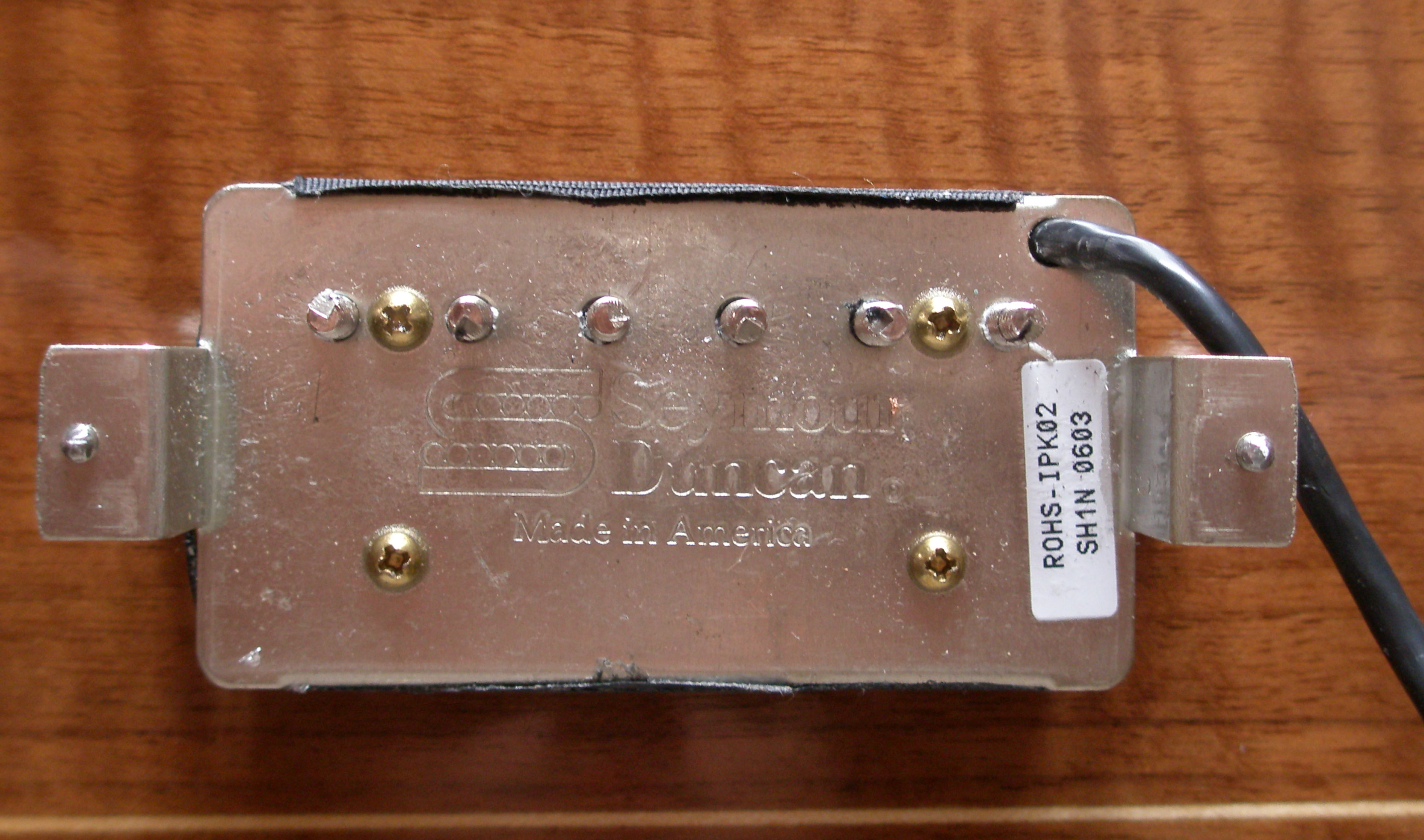 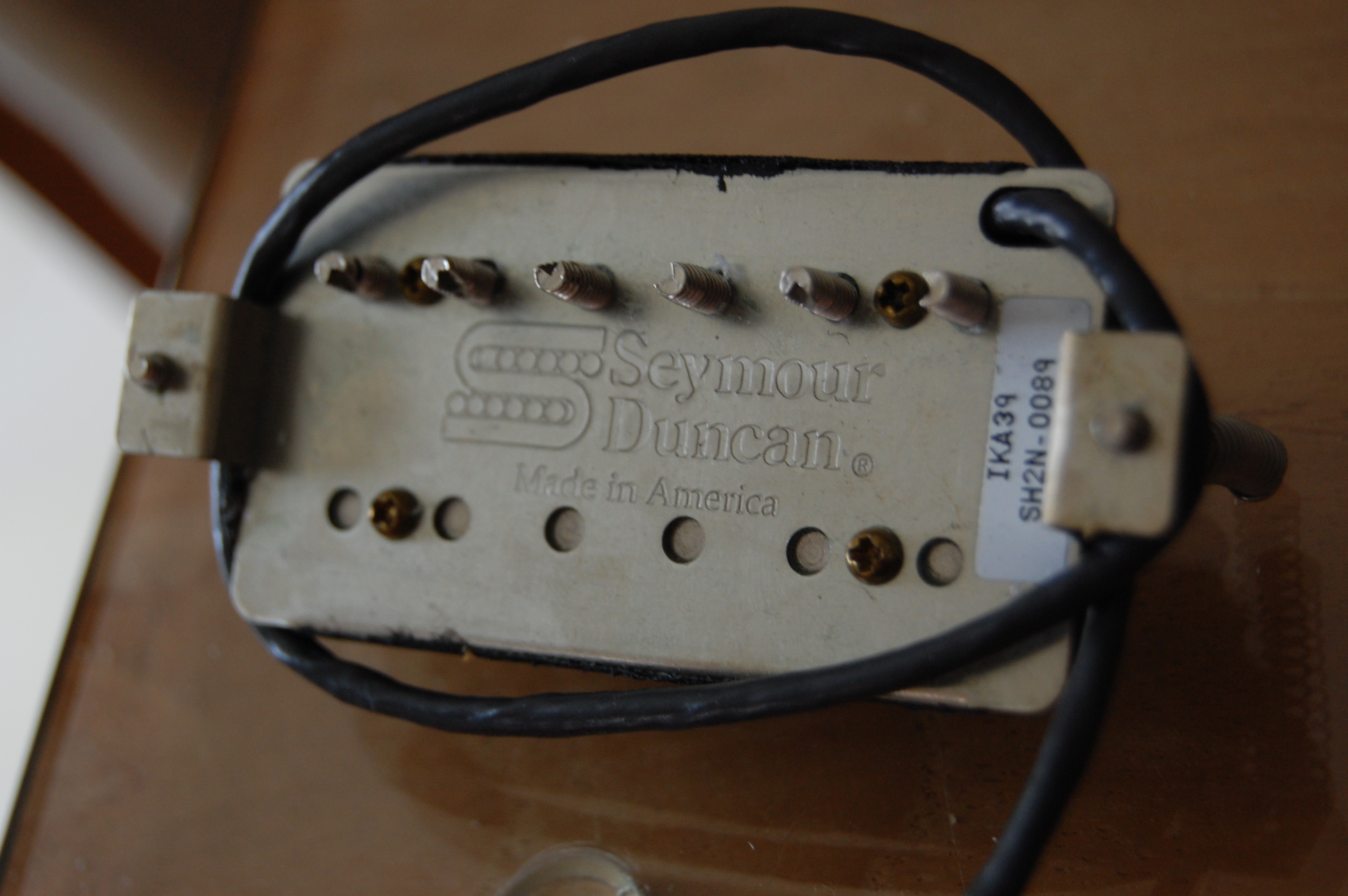 |
|
|
|
Post by Charlie Honkmeister on Feb 5, 2017 16:48:52 GMT -5
Mike, can you run both impedance and gain tests with, say, JohnH's, stratotarts and antigua's standard load of 200K ohms and 470 pF, and have both tests work computationally? I apologize if I missed any dicussion on this previously.
I'm curious to see if for the frequency range of interest in current passive instruments, basically 6 KHz and below, how the eddy current loss results jibe with JohnH's measurement methodology and parametrization of modeling data. I think they are leading to the same place, based on JohnH's reworking of some of his data into real and imaginary plots.
It is good to have both modeling and measurement, and from there we can not only characterize existing magnetic pickups, but also have a means of guiding new design and evaluating new designs against old.
|
|
|
|
Post by ms on Feb 6, 2017 12:46:17 GMT -5
Here is the comparison for the SH1N (PAF type neck pickup): The dip at the lower frequencies is interesting and probably audible. Presumably the steel in this pickup is not the same as in the SH2N. I would expect the slugs to be different, but also the pickups do not use the same screws. Those in the SH1N are just a bit fatter and very slightly longer. So we're seeing two plot lines; one plot line is response as measured through the wires, and the other is response as measured through the exciter coil, so as to see which eddy current losses effect to just magnetic field of the coil, and those which effect the fields of both the coil and the guitar string? I didn't think they would use different parts for the Jazz and the '59 neck models. I'm surprised to hear that they would use separate screws for the two models. It seems like a strange distinction to make. One thing I do know if that the '59 that comes with the braided one conductor wire is different in various ways from the '59 that comes with the 4 conductor wire; the two conductor version as a real wood spacer and longer mounting legs. In the case of the impedance measurement, we measure eddy current effects that result from current in the coil; that is, the eddy currents that affect the operation of the electrical circuit. Using the exciter coil, we see those effects and another kind. The exciter coil (or string) makes a time varying magnetic field. This field induces currents in the cores (or other metal). These induced currents make a magnetic field. It is the sum of the two that induces voltage in the pickup coil. (We expect the total field to be less than the original, but I doubt that the phase between the two is exactly 180 degrees.) If you sell something as a PAF replacement, I would think you should get the materials right, so it does not surprise me that the steel is different from other pickups. Here is the comparison for the slug coil of the foreign PAF type replacement I have mentioned before:  It shows a similar dip, but even more pronounced. |
|
|
|
Post by ms on Feb 6, 2017 12:51:43 GMT -5
Mike, can you run both impedance and gain tests with, say, JohnH's, stratotarts and antigua's standard load of 200K ohms and 470 pF, and have both tests work computationally? I apologize if I missed any dicussion on this previously. I'm curious to see if for the frequency range of interest in current passive instruments, basically 6 KHz and below, how the eddy current loss results jibe with JohnH's measurement methodology and parametrization of modeling data. I think they are leading to the same place, based on JohnH's reworking of some of his data into real and imaginary plots. It is good to have both modeling and measurement, and from there we can not only characterize existing magnetic pickups, but also have a means of guiding new design and evaluating new designs against old. I think that would be a good check. If you have the impedance measurement and the gain difference as illustrated i those plots, it should be possible to compute the gain with the load. And that is exactly what would be checked! |
|
|
|
Post by antigua on Feb 6, 2017 14:06:13 GMT -5
So we're seeing two plot lines; one plot line is response as measured through the wires, and the other is response as measured through the exciter coil, so as to see which eddy current losses effect to just magnetic field of the coil, and those which effect the fields of both the coil and the guitar string? I didn't think they would use different parts for the Jazz and the '59 neck models. I'm surprised to hear that they would use separate screws for the two models. It seems like a strange distinction to make. One thing I do know if that the '59 that comes with the braided one conductor wire is different in various ways from the '59 that comes with the 4 conductor wire; the two conductor version as a real wood spacer and longer mounting legs. In the case of the impedance measurement, we measure eddy current effects that result from current in the coil; that is, the eddy currents that affect the operation of the electrical circuit. Using the exciter coil, we see those effects and another kind. The exciter coil (or string) makes a time varying magnetic field. This field induces currents in the cores (or other metal). These induced currents make a magnetic field. It is the sum of the two that induces voltage in the pickup coil. (We expect the total field to be less than the original, but I doubt that the phase between the two is exactly 180 degrees.) If you sell something as a PAF replacement, I would think you should get the materials right, so it does not surprise me that the steel is different from other pickups. Here is the comparison for the slug coil of the foreign PAF type replacement I have mentioned before: It shows a similar dip, but even more pronounced. OK, I think I understand, and this is why I have used an exciter coil for testing, in order to get a realistic response as it relates to the strings, and not just that of the coil as a standalone RLC low pass. Since the "direct" method is a little easier to arrange than the exciter method, I think it's also a convenient way to get the resonant peak really quickly, if you're not concerned with an impedance plot that depicts all of the eddy current related losses. I'm not sure what you mean by the sum being effected by the eddy currents being less than 180 degrees out of phase with the coil. Due to Lenz'slaw, I would expect that they should be perfectly oppositional. What would cause the eddy current field to be an imperfectly opposed phase? Regarding the materials, I can believe they would make a '59 more authentic and the Jazz less so, but I would be surprised if they designs called for specific grades of steel, or rather, were specifically different for these two models. I know that the MEF pickup makers occasionally discuss the differences to be had with different grades of steel, but it's all very vague, and IIRC all the popular choices are very similar with respect to conductivity and permeability. I would sooner suspect that the differences were unintended on their part. |
|
|
|
Post by ms on Feb 6, 2017 15:23:37 GMT -5
In the case of the impedance measurement, we measure eddy current effects that result from current in the coil; that is, the eddy currents that affect the operation of the electrical circuit. Using the exciter coil, we see those effects and another kind. The exciter coil (or string) makes a time varying magnetic field. This field induces currents in the cores (or other metal). These induced currents make a magnetic field. It is the sum of the two that induces voltage in the pickup coil. (We expect the total field to be less than the original, but I doubt that the phase between the two is exactly 180 degrees.) If you sell something as a PAF replacement, I would think you should get the materials right, so it does not surprise me that the steel is different from other pickups. Here is the comparison for the slug coil of the foreign PAF type replacement I have mentioned before: It shows a similar dip, but even more pronounced. OK, I think I understand, and this is why I have used an exciter coil for testing, in order to get a realistic response as it relates to the strings, and not just that of the coil as a standalone RLC low pass. Since the "direct" method is a little easier to arrange than the exciter method, I think it's also a convenient way to get the resonant peak really quickly, if you're not concerned with an impedance plot that depicts all of the eddy current related losses. I'm not sure what you mean by the sum being effected by the eddy currents being less than 180 degrees out of phase with the coil. Due to Lenz'slaw, I would expect that they should be perfectly oppositional. What would cause the eddy current field to be an imperfectly opposed phase? Regarding the materials, I can believe they would make a '59 more authentic and the Jazz less so, but I would be surprised if they designs called for specific grades of steel, or rather, were specifically different for these two models. I know that the MEF pickup makers occasionally discuss the differences to be had with different grades of steel, but it's all very vague, and IIRC all the popular choices are very similar with respect to conductivity and permeability. I would sooner suspect that the differences were unintended on their part. The current that flows in response to a magnetic field could be flowing in a circuit that has inductance and/or capacitance. Thus the phase can be shifted. But it must dissipate energy, not create it, and that limits how it can shift. There is at least one pickup maker, not posting so much any more on MEF, who has claimed that he has done the research to determine what the steel was in PAFs and that it matters. In any case materials do matter. How else do you explain the dip in response present in the response of some pickups, but not others? |
|
|
|
Post by antigua on Feb 6, 2017 15:34:15 GMT -5
It's probably a lot to ask, but you could try swapping the slugs and poles and see if the impedance plots follow them around. I'm willing to test different screws and slug alloys if there is a supplier. I'd like to do this, I just have a back log of testing and other related projects.
BTW, it looks like your plots show resonant peaks well beyond 10kHz, am I interpreting that wrong?
|
|
|
|
Post by ms on Feb 6, 2017 16:13:28 GMT -5
It's probably a lot to ask, but you could try swapping the slugs and poles and see if the impedance plots follow them around. I'm willing to test different screws and slug alloys if there is a supplier. I'd like to do this, I just have a back log of testing and other related projects. BTW, it looks like your plots show resonant peaks well beyond 10kHz, am I interpreting that wrong? I was just thinking that that is the next test to do! Yes, I do see peaks above 10 KHz, but not always. Here is the SD SH4:  Note that I have not plotted above 10KHz. This pickup is is a 16K bridge pickup, often sold in a set with the SH2N. I suspect that the steel is the same in the two pickups. The impedance method I use should not load the pickups with any significant C. I made an effort to get the input C in the HiZ buffer down pretty low, but could not get below 11.6pf. Thus when computing the response from the impedance, I add 11.6pf for comparison purposes with the gain measurements. |
|
|
|
Post by antigua on Feb 6, 2017 18:27:31 GMT -5
Hmm, I get resonant peaks well below 10kHz for these same pickups, and I don't think I'm imposing a whole lot of capacitance, although.. are you bypassing the stock hookup wire? I've seen up to 70pF from the braided hookup wire.
|
|
|
|
Post by ms on Feb 6, 2017 18:56:33 GMT -5
Hmm, I get resonant peaks well below 10kHz for these same pickups, and I don't think I'm imposing a whole lot of capacitance, although.. are you bypassing the stock hookup wire? I've seen up to 70pF from the braided hookup wire. I am using the stock cable, about 13". My two measurement methods are consistent. |
|
|
|
Post by ms on Feb 6, 2017 19:07:01 GMT -5
The attached plot is the slug coil from the foreign humbucker, stock results above. I took out the stock slugs and replaced them with some I bought a while ago, probably from StewMac. There is much less dip; the resonant peak is higher in level and its frequency is higher. This is consistent with significantly lower eddy current losses, at least partly through lower permeability. (I seem to be picking up a bit of noise tonight that should not be there; have not been able to find the source.) My conclusion is that materials matter, and that buying random materials will get you random results.  |
|
|
|
Post by antigua on Feb 6, 2017 19:19:05 GMT -5
The attached plot is the slug coil from the foreign humbucker, stock results above. I took out the stock slugs and replaced them with some I bought a while ago, probably from StewMac. There is much less dip; the resonant peak is higher in level and its frequency is higher. This is consistent with significantly lower eddy current losses, at least partly through lower permeability. (I seem to be picking up a bit of noise tonight that should not be there; have not been able to find the source.) My conclusion is that materials matter, and that buying random materials will get you random results. I just the slug coil being analyzed, or is the screw coil still in series with it? I wonder if the difference between the 59 and Jazz steel properties is intentional or not. I have swapped screws in slugs between pickups in other tests and found that the differences were pretty small in those cases. It's hard to say what all factors were involved, but one thing is for sure, with added loaded, the Q factor drops to around 2 to 5dB amplitude, the resonance frequency is closer to 3kHz, and you see less pronounced differences with respect to eddy currents, whether it be from a cover or whatever. |
|
|
|
Post by ms on Feb 6, 2017 19:42:34 GMT -5
The attached plot is the slug coil from the foreign humbucker, stock results above. I took out the stock slugs and replaced them with some I bought a while ago, probably from StewMac. There is much less dip; the resonant peak is higher in level and its frequency is higher. This is consistent with significantly lower eddy current losses, at least partly through lower permeability. (I seem to be picking up a bit of noise tonight that should not be there; have not been able to find the source.) My conclusion is that materials matter, and that buying random materials will get you random results. I just the slug coil being analyzed, or is the screw coil still in series with it? I wonder if the difference between the 59 and Jazz steel properties is intentional or not. I have swapped screws in slugs between pickups in other tests and found that the differences were pretty small in those cases. It's hard to say what all factors were involved, but one thing is for sure, with added loaded, the Q factor drops to around 2 to 5dB amplitude, the resonance frequency is closer to 3kHz, and you see less pronounced differences with respect to eddy currents, whether it be from a cover or whatever. This is just the slug coil. Certainly the load tends to hide the differences, and so using the unloaded coil gives more accurate measurements. We just have to verify that using such results to model the loaded case is accurate. |
|
|
|
Post by ms on Feb 8, 2017 7:58:02 GMT -5
Sometimes looking at extreme cases can help build insight into what is happening. So here is the gain comparison (derived from impedance measurements and from exciter coil measurements like the other plots) for the SD hot rails.  This is a very high output (2 V p-to-p on the initial transient of a power chord) single coil sized pickup with a very low unloaded resonance peak frequency. That is, if you use it with a FET buffer in the guitar unloaded, it sounds much like a normal humbucker loaded with pots and cable. It is about 13H and 17K. The direct eddy current loss (that is, the loss from cancelation of the magnetic field from the vibrating string or exciter coil from currents in the steel) is very large as the plot shows. The reason that it does not display the dip in response at the lower frequencies is that the resonance is so low that the consequent rise in response covers it up. |
|


