|
|
Post by Ro_S on Mar 9, 2018 20:33:35 GMT -5
I have a major wiring and mod project planned for my Squier Jagmaster guitar, and have now completed my initial plans for this project. The advice, views and wisdom of members of this forum in regards to my project's intended mods and wiring etc. is now sought and would be greatly appreciated. I have set out my plans graphically in the annotated diagram posted below. (NB. this is not intended to constitute a wiring diagram, but parts of the diagram do show complete proposed wiring.) The diagram below - imgur.com/89gnWvT - contains lots of information and should hopefully be self explanatory, but I shall set out a resume of things below. Please can I have people's concerns, errors, feedback and suggestions about my proposed plans. Thankyou.I wish to stress that I fully appreciate that my plans for this guitar are (i) quite elaborate and (ii) that pickup selector changes will not always be quick or simple to execute. That's okay, however. I have a number of guitars and this particular guitar is going to be a donor for alterations that will constitute an experimental project guitar of sorts. A key part of the project represents including Danelectro lipstick style pickups and allowing them to be used both on their own - both singularly and in series together - as well as in conjunction wired in series with other pickups to essentially produce unusual custom dual coil and triple coil pickups configurations. SUMMARY OF PROPOSED MODS & WIRING: Four pickups: - in the bridge position, a humbucker-sized THREE coil pickup which can be wired and split in a variety of ways. Each 'rail' coil has a DC resistance of approx 5k. - in the neck position, a P90 style pickup (humbucker sized casing). - TWO Danelectro style lipstick pickups (approx 4k DC resistance each ), located in between the above pickups. Note: the two lipstick pickups have the same polarity. Switching: Pickups to be selected via 4 switches in total. The bridge triple coil pickup to have its own 4-way or 5-way mode selector switch for different wiring permutations of its three 'rail' coils. The two lipsticks to have a 3-way toggle switch (on/off/on DTDP) to allow either pickup alone or both in series (as per the vintage Danelectro wiring). A 5-way rotary switch (5P4T) to select the configuration of the outputs of the bridge pickup and the lipstick pickups. A typical 3-way (Gibson style) toggle switch to select between the above and the neck pickup or both in parallel. Volume and tone controls to function globally. I intend all pots to be 500k and audio taper. The volume control is to include a treble bleed circuit. Dual passive tone controls, similar to the G&L 'PTB' scheme, comprising a treble cut control and a bass cut control. Link to proposed mod. see: www.premierguitar.com/articles/21112-three-must-try-guitar-wiring-modsThe treble cut tone control circuit to incorporate a variable tone capacitor selector (rotary) switch allowing a choice between 6 capacitors of different values. I chose this instead of a varitone type circuit. Link to proposed mod, see: (ignore the humbucker bit) www.premierguitar.com/articles/26156-mod-garage-the-quad-pot-dual-humbucker-wiring-of-doomI have not decided on any proposed cap values. Suggestions? Momentary kill switch in the form of a push button. 'Direct through' mod. 2-way switch. This bypasses all volume and tone controls/circuits, wiring the selected pickup configuration direct to the output jack. (This is slightly different to a ''blower switch'' mod.) Link to proposed mod. see: www.premierguitar.com/articles/Stratocaster_Direct_Through_Mod NB. the above is NOT intended to be a wiring diagram, but parts of the diagram do show complete proposed wiring. Link to diagram where you can enlarge it: imgur.com/89gnWvT |
|
|
|
Post by sumgai on Mar 9, 2018 21:31:53 GMT -5
Ro_S,
You're going to have a problem with your Solo switch, albeit that you didn't intend for the current settings to be permanent. I was going to get all educative on you, but whilst doing so, newey popped in and answered another member's question, and included a diagram that you're going to need. This is exacly how you'll want to hook up your switch. Don't worry that it's a push-pull, and yours isn't - the functionality is the exact same, regardless of the physical mounting details.
Proper solo switch wiring
HTH
sumgai
|
|
|
|
Post by newey on Mar 9, 2018 22:32:13 GMT -5
There's a lot to digest here, and it's giving me gas . . . If you manage to fit all this in the guitar, please post guts shots so we can see it.
But for starters, I note that your momentary kill switch is wired off the Vol. control, which means that it won't work when you have the pots bypassed by the "direct out" switch. if you want it to work regardless of the position of the Direct switch, you would need to use a two-pole momentary button (these are likely available, although I haven't looked). One pole would kill the signal with the pots in circuit, the other when they weren't.
I suspect you mean a 4P5T switch. In any event, what are the configurations? There is already a separate switch to select the lipsticks, single/series/single, so we just have a single output from both tube pickups to this 5-way rotary. And the Bridge triple coil is also already selected by it's own switch, so that output then goes to this rotary.
So, I see the rotary selecting:
1) Tubes alone
2) HB alone
3) Tubes + HB (i.e., parallel)
4)Tubes X HB (series)
But that's only 4 selections. What do you want to do with the 5th position?
|
|
|
|
Post by Ro_S on Mar 9, 2018 22:51:15 GMT -5
Ro_S,
Let me just shortcut all the folderol, and link to an earlier post that dealt with the exact same problem: My blower switch don't blow.
That's a single post, but it won't show the whole thread - that's here.
Note how the thread's original poster fixed the problem, then incorporate that into your diagram. Presto, you're one step closer to that Mojo Tone!
HTH
sumgai
I have a DPDP 2-way Jaguar/Jazzmaster slider style switch I shall be using for this purpose. Here is the wiring diagram I found for this mod:  Correct., yes? HOWEVER, because I am using a dual PTB tone control circuit, I have to wire the hot to the treble cut pot - and then via the bass cut pot - rather than to the volume pot. Correct? That is what it indicates in this wiring diagram I obtained for the PTB mod; see here: imgur.com/Od6aHI4I have added the wiring to my diagram, here is extract of the revised diagram:  Correct? |
|
|
|
Post by Ro_S on Mar 9, 2018 23:56:58 GMT -5
So, I see the rotary selecting: 1) Tubes alone 2) HB alone 3) Tubes + HB (i.e., parallel) 4)Tubes X HB (series) But that's only 4 selections. What do you want to do with the 5th position? I put this on the diagram in the orange coloured box, but I'll express it again and differently: 1) lipsticks only 2) bridge pickup only 3) lipsticks + bridge pickup [in parallel] 4) lipsticks X bridge pickup [in series] in phase 5) lipsticks X bridge pickup [in series] out of phase Btw, the guitar has plenty of cavity routing!  |
|
|
|
Post by Ro_S on Mar 10, 2018 0:03:21 GMT -5
I note that your momentary kill switch is wired off the Vol. control, which means that it won't work when you have the pots bypassed by the "direct out" switch. if you want it to work regardless of the position of the Direct switch, you would need to use a two-pole momentary button (these are likely available, although I haven't looked). One pole would kill the signal with the pots in circuit, the other when they weren't. Yes, thanks, that's true. That design was kinda semi deliberate on my part. It allows for some pseudo duo kill switch madness, as the direct through switch can effectively work as a kill switch too (if the volume control is set low/off). I was also conscious about long wiring runs; I want the momentary switch close to the volume control on the scratchplate, which is far away from the output jack. |
|
|
|
Post by thetragichero on Mar 10, 2018 11:52:00 GMT -5
that's a... lot of knobs and switches you have there!
if this is just an experiment to see what everything does then have at it, but i can see issues trying to get a good sound out of something in poor fluorescent lighting with a bunch of people staring at me... i find making something as simple as possible helps a hack like me get a usable tone when i'm sweating and nervous (my first posts on this forum were for a "strat that does it all" with HB, p90, and single coil, FWIW, and the resulting wiring/pickguard is currently under the bench for a more traditional SSS build)
regardless, i am interested in seeing how this turns out! (i tried sussing out the wiring diagram and my brain decided it didn't want to cooperate)
|
|
|
|
Post by Ro_S on Mar 10, 2018 14:03:59 GMT -5
that's a... lot of knobs and switches you have there! if this is just an experiment to see what everything does then have at it, but i can see issues trying to get a good sound out of something in poor fluorescent lighting with a bunch of people staring at me. This modded guitar is intended strictly to be for home and recording use. |
|
|
|
Post by sumgai on Mar 10, 2018 14:55:57 GMT -5
I note that your momentary kill switch is wired off the Vol. control, which means that it won't work when you have the pots bypassed by the "direct out" switch. if you want it to work regardless of the position of the Direct switch, you would need to use a two-pole momentary button (these are likely available, although I haven't looked). One pole would kill the signal with the pots in circuit, the other when they weren't. Yes, thanks, that's true. That design was kinda semi deliberate on my part. It allows for some pseudo duo kill switch madness, as the direct through switch can effectively work as a kill switch too (if the volume control is set low/off). I was also conscious about long wiring runs; I want the momentary switch close to the volume control on the scratchplate, which is far away from the output jack. This is why newey admonished newcomers to have a second set of eyes on whatever he does.
In fact, as shown in both diagrams (original and revised), the kill switch works, period... no regards as to where the solo switch is positioned, the final output signal will be dead on arrival.
The reason for this is that you did not take into consideration that newey "simplified" his diagram (call it a module, 'cause that's what it is) by leaving out the Tone control(s). You simply tied the switch's two upper terminals to the Tone controls, instead of the Vol pot. This created a condition we call a Romper Room No-No. The intent of newey's drawing was to show you how to isolate the two signal paths (Vol out and direct out) so that the Volume pot could not control the volume level when you selected the direct out (Solo mode) position. Sadly, your lastest revision needs further revising. (But that's the nature of the game, no?  ) )
After that, place the kill switch directly across the output jack terminals (using direct contact points within your control cavity), and it will work as intended, at all times.
BTW, having a stutter switch with a spring is considered a better option than rapidly flicking back-and-forth a switch that was not built for that kind of action. Yes, it's your switch, you paid good money for it and you have the right to treat it however you wish. But keep in mind that no manufacturer can foresee all manner of possible abuse. Further, when it comes time to replace the worn-out thing, you'll probably be paying a higher price... unless you laid in a stock of the things at the outset. 
Keep plugging away, grasshopper, we'll see you get to your goal yet!
HTH
sumgai
|
|
|
|
Post by JohnH on Mar 10, 2018 16:13:24 GMT -5
Just looking at the diagram so far, there is some oddity around the tone wiring, though nothing non-fixable. If you are using normal log-taper pots, bofh controls should just use two lugs not three. Move the bass-cut cap to the same two lugs as the wires. (middle and right as drawn). Same two lugs used on the treble cut. To get the best performance with tbe widest range, Id suggest changing pot values from 500k to 250k log volume, 250k no-load log treble cut and 1M log bass cut. There should be no change in the full treble and bass tones from that change. Some prefer a reverse log pot for bass cut (swap outer wire lug), but they are rarer. With reverse log, max bass is at 10 while with normal log it is at 0 on tbe knob. This thread may assist: Bass cut and the PTB system |
|
|
|
Post by Ro_S on Mar 10, 2018 21:28:24 GMT -5
Thanks for the replies so far. I'll reply and address the issues, but first I have a basic question as I may have confused myself about something:
Stupid question, sorry:
Convention wise, on wiring diagram, which way up are the 2D pots depicted? I mean, is the shaft on the 'other' side'? Is one seeing the 'rear' (the other side of the shaft) of the pot as if the pot is mounted to a scratchplate? Which is lug 1 and which is lug 3?
|
|
|
|
Post by Ro_S on Mar 10, 2018 21:54:58 GMT -5
To get the best performance with tbe widest range, Id suggest changing pot values from 500k to 250k log volume, 250k no-load log treble cut and 1M log bass cut. There should be no change in the full treble and bass tones from that change. Some prefer a reverse log pot for bass cut (swap outer wire lug), but they are rarer. With reverse log, max bass is at 10 while with normal log it is at 0 on tbe knob. Thanks. Questions: 1. you suggest 1meg for the bass cut pot - Won't 1meg brighten the base tone of the guitar too much? 2. you suggest 250k no-load for the treble cut pot. Why is the no-load aspect necessary/suggested? How important is the no-load aspect? I'm trying to be frugal; no-load post cost about £10 (us$17)? If possible, I'd like to avoid buying a no-load pot - unless it comprises things too much? Won't a no-load pot brighten the base tone of the guitar to much (compared to a normal pot)? How does one compensate for that? If not using a no-load pot, would you advise 500k as a substitute? thanks! |
|
|
|
Post by JohnH on Mar 10, 2018 21:56:12 GMT -5
Thanks for the replies so far. I'll reply and address the issues, but first I have a basic question as I may have confused myself about something: Stupid question, sorry: Convention wise, on wiring diagram, which way up are the 2D pots depicted? I mean, is the shaft on the 'other' side'? Is one seeing the 'rear' (the other side of the shaft) of the pot as if the pot is mounted to a scratchplate? Which is lug 1 and which is lug 3? That's a great question. We draw them with the shafts on the other side, which is the view you have when you are wiring them up. I think that is by far the most common and useful convention. |
|
|
|
Post by JohnH on Mar 10, 2018 22:03:12 GMT -5
To get the best performance with tbe widest range, Id suggest changing pot values from 500k to 250k log volume, 250k no-load log treble cut and 1M log bass cut. There should be no change in the full treble and bass tones from that change. Some prefer a reverse log pot for bass cut (swap outer wire lug), but they are rarer. With reverse log, max bass is at 10 while with normal log it is at 0 on tbe knob. Thanks. Questions: 1. you suggest 1meg for the bass cut pot - Won't 1meg brighten the base tone of the guitar too much? 2. you suggest 250k no-load for the treble cut pot. Why is the no-load aspect necessary/suggested? How important is the no-load aspect? I'm trying to be frugal; no-load post cost about £10 (us$17)? If possible, I'd like to avoid buying a no-load pot - unless it comprises things too much? Won't a no-load pot brighten the base tone of the guitar to much (compared to a normal pot)? How does one compensate for that? If not using a no-load pot, would you advise 500k as a substitute? thanks! Have a look at that link I posted. The great thing about a bass-cut control done this way is that at max bass, it has no effect at all, so no compromise to your basic tone. A 1M will give you a bit more max bass-cut range if you want it, but both have no effect at min bass cut. Bass cut works to make an RC filter when combined with the volume pot, so a 250k volume pot makes it more effective than a 500k volume pot. Changing the treble pot from 500k to no-load compensates to leave you exactly the same basic tone. But if you want to use all 500k, it will still work fine, just not quite as effectively. |
|
|
|
Post by Ro_S on Mar 13, 2018 17:17:15 GMT -5
In fact, as shown in both diagrams (original and revised), the kill switch works, period... no regards as to where the solo switch is positioned, the final output signal will be dead on arrival.
The reason for this is that you did not take into consideration that newey "simplified" his diagram (call it a module, 'cause that's what it is) by leaving out the Tone control(s). You simply tied the switch's two upper terminals to the Tone controls, instead of the Vol pot. This created a condition we call a Romper Room No-No. The intent of newey's drawing was to show you how to isolate the two signal paths (Vol out and direct out) so that the Volume pot could not control the volume level when you selected the direct out (Solo mode) position. Sadly, your lastest revision needs further revising. (But that's the nature of the game, no? )
After that, place the kill switch directly across the output jack terminals (using direct contact points within your control cavity), and it will work as intended, at all times.
I'm afraid I don't understand what you're getting at here.  Are you saying that the way I've proposed the wiring of the momentary kill switch - diagram above - won't work at all? You want me to wire it at the output jack? Will that work with the "direct through" mod wire going their, too? |
|
|
|
Post by Ro_S on Mar 13, 2018 17:27:10 GMT -5
I've revised my wiring diagram. There are several changes. See below. Please can ppl peruse/check it, Thankyou.  |
|
|
|
Post by sumgai on Mar 13, 2018 19:10:17 GMT -5
I'm afraid I don't understand what you're getting at here. Are you saying that the way I've proposed the wiring of the momentary kill switch - diagram above - won't work at all? You want me to wire it at the output jack? Will that work with the "direct through" mod wire going their, too?
Not quite. I said that the kill switch works at all times, regardless of the Solo switch position. That is the way most guitarists find it useful, but of course, you can have it which ever way you want - that's the beauty of designing your own circuitry!
What I did say was that the Volume control still controls the output signal - the Solo ("blast") switch is completely ineffective. Fix it like this;
Take the two purple lines from the top two terminals of the Solo switch off the Treble pot. Now put them on the same two terminals of the Volume pot - right on top of the other wires. Next, remove the purple wire between the Vol pot's wiper (the center terminal) and the output jack... the one you labeled as "Hot". Rewiring these two items will make the Solo switch work as you intend.
Next up, the Kill switch. Do you want it to work only when the Solo switch is in "Normal" position, or do you want it to work at all times?
sumgai
|
|
|
|
Post by Ro_S on Mar 13, 2018 19:33:07 GMT -5
I'm afraid I don't understand what you're getting at here. Are you saying that the way I've proposed the wiring of the momentary kill switch - diagram above - won't work at all? You want me to wire it at the output jack? Will that work with the "direct through" mod wire going their, too?
Not quite. I said that the kill switch works at all times, regardless of the Solo switch position. That is the way most guitarists find it useful, but of course, you can have it which ever way you want - that's the beauty of designing your own circuitry!
What I did say was that the Volume control still controls the output signal - the Solo ("blast") switch is completely ineffective. Fix it like this;
Take the two purple lines from the top two terminals of the Solo switch off the Treble pot. Now put them on the same two terminals of the Volume pot - right on top of the other wires. Next, remove the purple wire between the Vol pot's wiper (the center terminal) and the output jack... the one you labeled as "Hot". Rewiring these two items will make the Solo switch work as you intend.
Next up, the Kill switch. Do you want it to work only when the Solo switch is in "Normal" position, or do you want it to work at all times?
sumgai Re: 'direct through' mod (or solo blast switch as you call it) - Please note that I want this mod to bypass both the volume pot and tone pots, not just the tone pots. Will the change you propose still achieve this? Re: position and wiring of the 'direct through' mod (or solo blast switch as you call it) - You're aware I've incorporated a bass cut tone control, yeah? I'm having a G&L style 'PTB' (passive treble bass) tone circuit.On all the 'PTB' wiring diagrams I have seen, the hot signal from the master pickup selector switch has to go via the (bass cut) tone pot, not to the volume control. see: www.bassesbyleo.com/images/guitar_circuits/legacy/legacy_block_diagram.jpgWill the change you propose - wiring direct to the volume pot (the normal way?) - work with my PTB tone circuit? Re: momentary kill switch - Ideally, this would work all the time regardless of what mode the 2-way 'direct through' mod switch is in. However, I am concerned about avoiding long cable runs in the circuit? That's why I proposed wiring the kill switch to the volume pot rather than the output jack. What do you think? thanks! |
|
|
|
Post by sumgai on Mar 13, 2018 20:09:44 GMT -5
Re: 'direct through' mod (or solo blast switch as you call it) - Please note that I want this mod to bypass both the volume pot and tone pots, not just the tone pots. Will the change you propose still achieve this? Yes indeed, once you undertake the following steps, as I answer your other questions.
Let me interject here....
Over the years, we've had no dearth of names for this switch. It's proper name is a true bypass, as it does exactly that, just like in a stompbox, and for the exact same reasons - to lessen any tone-killing effects from circuit loading. Solo, blast, direct out, even honker was used once. It's all the same, and we here in the NutzHouse will pretty much always understand a player's intent, regardless if they don't know what we've called it in the past, and they make up yet another new name. Don't worry, eh?
Actually, you've caught me out. newey's diagram, which I approved of so gushingly, will not work as I described in my recent post. You do indeed need to put the lead from the left side of the Solo switch to the proper terminal of the Bass cut pot. But you still need to put the other lead (from the right side of the switch) to the Volume pot's wiper.
While we're at it, you still don't have the tone controls set up correctly. Your linked diagram is not "shoddy", but it's not attractive either. Try this instead: 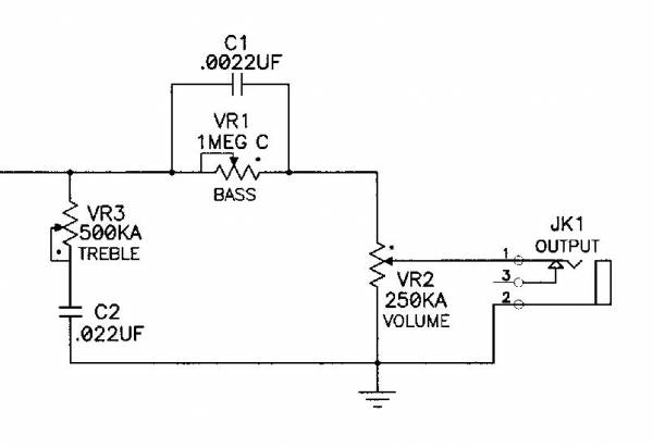
That comes from this thread, if you're interested: John's version of the PTB setup
I'm touched by your concerns... really!
In point of fact, unless you live in an industrial area where they ignore all manner of laws about electrical emissions, then you're not gonna suffer in the least just because you ran a 12" piece of wire inside of your guitar. Not your tone, and most decidely not any hum factor. What will hinder your efforts at reducing hum (in any "normal" environment) has been discussed ad finitum, ad naseum elsewhere on these boards. If you do a search, you'll find that length of wire runs has never been mentioned. Not once.... until now. 
Anyways....
I said, earlier, that you should place the kill switch (no ambituity on that name, right?) across the output jack. You originally did this in your first diagram, but you showed it as being across the Vol pot's wiper and the back of the pot (presumably a ground point). That's what I meant by choosing points inside of the cavity that are electrically the same as the output jack terminals, but may not be those points in physical reality. In this case, once the Vol pot is isolated by the switch to Normal only, then putting the kill switch there will not work at all times, only in Normal mode. Instead, put one wire anywhere you find ground, and the other wire on the right-center terminal of the Solo switch... presuming, once again, that it is located in a convenient spot. And is convenient to get to. Perhaps in your Jagmaster (I had one of those once), the jack is also convenient. It's a matter of what's easiest to solder, what's easiest to understand according to your diagram, and just as importantly, what will be the easiest to troubleshoot, should Mr. Murphy come calling in the middle of the night. 
HTH
sumgai
|
|
|
|
Post by Ro_S on Mar 13, 2018 20:31:44 GMT -5
@sumbai -
Many thanks.
I'll make the changes and post my revised wiring diagram.
Note: I'm afraid I don't understand circuit schematic diagrams such as the one you just posted. I know what the symbols mean but I can't translate them into wiring diagrams; they don't really mean anything to me unfortunately.
|
|
|
|
Post by thetragichero on Mar 13, 2018 20:56:37 GMT -5
solo switch + tone pot wiring are problematic
treble pot lug1should be unused - bass should be connected to treble lug3
treble lug2 shouldn't be connected to 'hot' from the solo switch, just to your rotary tone cap switch. this connection from the solo switch should instead go to volume pot lug2. erase the wire from volume pot lug2 to 'hot' on the jack
now for the killswitch... i am familiar with two basic types of momentary switches - normally closed and normally open. depending on which one you have would determine how it's wired, and it's a nice thing to discover before it's all back together and you're wondering why the durn thing won't make any sound
|
|
|
|
Post by thetragichero on Mar 13, 2018 20:58:10 GMT -5
|
|
|
|
Post by Ro_S on Mar 13, 2018 22:09:59 GMT -5
@sumbai - Okay, below is the new version. How have I done?  |
|
|
|
Post by Ro_S on Mar 13, 2018 22:14:45 GMT -5
now for the killswitch... i am familiar with two basic types of momentary switches - normally closed and normally open. depending on which one you have would determine how it's wired, and it's a nice thing to discover before it's all back together and you're wondering why the durn thing won't make any sound My ones are “push-to-make” (ON)-OFF momentary switch (aka “N.O. contacts” or normally open contacts) |
|
|
|
Post by thetragichero on Mar 13, 2018 22:18:32 GMT -5
remove green wire from volume pot to ' hot' jack. when solo switch isn't engaged, that connection to 'hot' is made via the switch now for the killswitch... i am familiar with two basic types of momentary switches - normally closed and normally open. depending on which one you have would determine how it's wired, and it's a nice thing to discover before it's all back together and you're wondering why the durn thing won't make any sound My ones are “push-to-make” (ON)-OFF momentary switch (aka “N.O. contacts” or normally open contacts) okay cool. 's a mistake I've made before so knowing whatcha have ahead of time saves a lot of grief later |
|
|
|
Post by Ro_S on Mar 13, 2018 22:25:17 GMT -5
|
|
|
|
Post by thetragichero on Mar 13, 2018 23:05:41 GMT -5
the difference in bass pot wiring is that a C1M (reverse audio taper)pot wired like it is on pg had max bass at 10 (just like treble pot with max treble at 10) instead of max bass cut at 10
|
|
|
|
Post by newey on Mar 14, 2018 5:47:41 GMT -5
TragicHero said:
Trage, you want to look at that again? He's got the switch disconnecting at the tone pot, and the volume is wired after that (i.e., the "'50s style wiring").
So, as I see it, he absolutely needs that green wire.
Ro_S:
This version looks OK, but your treble pot wiring is backwards, it's wired lefty. As you show the pots, they are shown from the backside, which is the way you'll be looking at them as you wire them up. We know this because you have designated the lugs as "3-2-1", left to right (and you also specified it was viewed from the back). Lug 3 is thus the clockwise lug (CW), the input needs to go there, not to lug #1.
|
|
|
|
Post by Ro_S on Mar 14, 2018 7:12:31 GMT -5
This version looks OK, but your treble pot wiring is backwards, it's wired lefty. As you show the pots, they are shown from the backside, which is the way you'll be looking at them as you wire them up. We know this because you have designated the lugs as "3-2-1", left to right (and you also specified it was viewed from the back). Lug 3 is thus the clockwise lug (CW), the input needs to go there, not to lug #1. treble pot lug1should be unused - bass should be connected to treble lug3 Does what you both advise above still apply regardless of whether or not the bass cut pot has a reverse taper? I ask cos on some of the PBT wiring diagrams I've using for reference, the wire from the bass cut pot to the treble cut pot is wired to lug #1 of the treble cut pot as opposed to lug #3. (is that cos they're using or not using a reverse taper bass cut pot? or is it cos I'm not wiring the hot from the pickup selector switch to the treble cut pot due to the 'direct through' mod complication I've introduced?) My intention is to NOT use a reverse taper pot for the bass cut pot - cos they're hard to get. Thanks [edited] |
|
|
|
Post by thetragichero on Mar 14, 2018 7:22:34 GMT -5
TragicHero said: Trage, you want to look at that again? He's got the switch disconnecting at the tone pot, and the volume is wired after that (i.e., the "'50s style wiring"). So, as I see it, he absolutely needs that green wwire to my eyes, the purple wire from the blower switch connects that lug to 'hot,' no? otherwise the volume pot is hangin' from hot when in solo mode? |
|


 )
)


