|
|
Post by thetragichero on Jan 21, 2021 0:29:16 GMT -5
so my old man extols the virtues of using mdf for making tooling. up until now I've been laying out each build on its own (or chaotically building point-to-point) which takes a LOT of time so i purchased a sheet of 1/4" mdf along with a bunch of vulcanized fiberboard and started making drill templates for eyelet boards for the "standard" builds (things I've tried and liked and would like to build more of)  still have to fashion a clamping jig with scrap but I've clamped one to the bench and have a board done with it as a proof of concept for an upcoming combo build so yay for time saving! |
|
|
|
Post by unreg on Jan 25, 2021 17:48:58 GMT -5
thetragichero, did you write a summary on the back of what each piece of mdf means? 🙂 I’d recommend doing that bc if your memory fails, that summary will quickly help you to make sense of the mdf. I experienced destruction of my memory and wished that I had written a summary/commented code; yes, piecing it back together is certainly possible, but the comments are surely welcome IMO. Writing the summary seems silly now, but those summaries may be golden sources of happiness in the future. 🙂
|
|
|
|
Post by thetragichero on Jan 25, 2021 17:52:36 GMT -5
each model's name is written on the back. as far as what wires go where it's either recognizing the resistor values and where they go (resistor in the 100ks and a capacitor? that goes to a preamp tube plate somewhere) and referring to the schematics when all else fails
|
|
|
|
Post by thetragichero on Feb 27, 2021 3:05:23 GMT -5
gear exchange around Christmas ended up with me getting a TON of old transistors and other parts. different about a buck for four small turret boards at the local electronics surplus store awhile back and figured I'd throw together a few simple one-off fuzz builds this is the first, which i guess I've gotta box up now. colorsound one knob fuzz with a second knob (shhhh) to adjust the bias. first transistor is a metal can 2n2222a, second is an ecg103a npn germanium  i don't mind this type of layout nearly as much as i do with little components on perf. simple stuff |
|
|
|
Post by thetragichero on Mar 3, 2021 0:00:17 GMT -5
another turret board dirt box waiting to be boxed up. this is based off the electra distortion, but with an npn germanium transistor and no diodes to ground (tried a dual gang pot bypassing the diodes until the volume is turned up but it sounded thin and buzzy like some of the bad dod distortion.... they make some good pedals though). more of a dirty boost than a full on fuzz/distortion, although with the neck pickup it gives some interesting intermodulation distortion with the low strings ringing out and playing the higher strings. no clue if it's a useful tone but it's interesting nonetheless  |
|
|
|
Post by frets on Mar 3, 2021 11:09:11 GMT -5
Trag, What I’m working on? Just finished the pickguard to a Strat I’m building. Predictably a Passive Treble Bass using original 50’s bumblebees (within 10%), Bootstrap Oatmeal Stout Pickups (I’m high on them - overwound).  On another subject, that Electra derived dirtbox circuit you made is interesting. You have a diagram? It’s a smaller circuit than mine. I’d do the asymmetric with it. Got the Russian transistors for it. |
|
|
|
Post by thetragichero on Mar 3, 2021 13:34:04 GMT -5
lemme redraw the layout into something legible and i'll post it up. resistor values were tweaked to get half supply voltage at the collector for the particular transistor in there (90 hfe ASY29)
previous fuzz i didn't even breadboard but it'll have a bias pot so should end up working despite my laziness
|
|
|
|
Post by thetragichero on Mar 3, 2021 14:16:45 GMT -5
 transistor and output cap drawn like that so the layout is easier to see. i used a 1M5 resistor on the input because i had it and I'll never use it. 39pf cap from base to ground helped me stop picking up a radio station. if you've got 33 or 47pf that should be sufficient (had one i pulled from old electronics) should've breadboarded it with a Ge side from emitter to collector to give it some temperature stability (I'm doing that on a rangemaster I'll be building into one of these turret boards) but since i didn't and i liked what i heard for now I'll leave it. sounds about the same with 500k volume pot as it does with 100k but if i can avoid having to find a parallel resistor for the 500k pots I'm all for it. maybe |
|
|
|
Post by frets on Mar 3, 2021 15:51:30 GMT -5
Trag, first off - thank you😽😽
I’ll be building it in the next week and will let you know what I think. I think I might do back to back diodes with it but I’ll try it out as is. I’m sure I’ll like it. It will then be turned into a pcb with 0805 smd’s. The footprint will be minuscule. I really appreciate you doing this for me. I prefer the Electra to just about any other.
What’s the value of the big right center cap on V+?
|
|
|
|
Post by thetragichero on Mar 3, 2021 17:00:39 GMT -5
oh lol forgot to put it in... i used 220uf because i had one that is old stock and wouldn't trust it in an amp build (i find it a waste of both time and money not to put new electro caps in amps from jump), but had no motorboating or issues here so i used it
otherwise i would've use 47uf, which should be plenty fine
keep in mind that the emitter, collector, and collector-base resistors were chosen empirically for this specific Ge transistor. if you're using something else/silicon I'd use either the original (680/47k/2M2) or what seems to appear in the more boutique clones (330/10k/10M). here's where a breadboard would help (how to breadboard smd? no clue)
|
|
|
|
Post by thetragichero on Mar 20, 2021 13:09:02 GMT -5
from two nights ago but I've been lazy getting pictures finished up my three "mojo" turret board dirt box builds   in various orders: electra-based npn germanium without the clipping diodes, sort of a dirty boost with a ton of bass owing to 220nf input and output caps npn germanium rangemaster, mostly stock (8nf input/output caps because i had em in the pretty bumblebee style). these first two work best into a crunchy amp and stack nicely together the two knob pedal is a colorsound one knob fuzz with a bias knob added. metal can 2n2222a (apparently the metal can and to92 have mirror image pinouts.... found this out while trying to test on the scope) and npn germanium transistors. bias knob changes fuzz character for the first quarter of its travel and then adjusts how gated the fuzz is i ran out of this size enclosure but have the bigger size, think I'll build the two one knob pedals into one with a switchable option or two. i much prefer this build style to perf. forces me to be simple |
|
|
|
Post by frets on Mar 20, 2021 15:04:26 GMT -5
Trag,
Those all look sweet!!
What about the Colorsound? I’ve been tempted to build one but was unsure of the crunch to it. Is it more of a fuzz pedal?
|
|
|
|
Post by thetragichero on Mar 20, 2021 15:45:38 GMT -5
this was made with lower gain transistors than the original so probably not a fair comparison but it's not even close to muff territory
i know i tell you this often but: breadboard it. if it's too much you can add a couple hundred ohm resistor between first stage emitter and ground
it is, of course, YAFF (yet another fuzz face) so you can use that as a template for further mods. adjusting the 150k feedback resistor up or down could also provide tweakability
|
|
|
|
Post by frets on Mar 20, 2021 17:11:00 GMT -5
You’re right Trag,
I need to breadboard more. I think I will as I’ve only started doing pedals for a little bit of time. Thanks for letting me know that it’s another fuzz. I’m just beginning to explore what pedals I feel I would like to build. I have a gazzillion
pedals but they’ve basically told me what I don’t like; or, what I wished a particular pedal would do a bit more of. The next pedal I build will be John’s overdrive. I’m still on the pursuit for the perfect overdrive.
|
|
|
|
Post by JohnH on Mar 20, 2021 17:29:58 GMT -5
The next pedal I build will be John’s overdrive. I’m still on the pursuit for the perfect overdrive. Cool, you'll build it better than I could. There's a few watchits/things to know, so let's discuss on its own thread before you start, whenever you are ready. |
|
|
|
Post by frets on Mar 21, 2021 12:51:26 GMT -5
John,
I will let you guys know when I start to build the pedal. It will be great to breadboard it and have input as to how to tweak it to be my perfect Overdrive. I’ve already sent off for the J2N547’s. I’m really looking forward to crafting this pedal. Thanks!! 😺😺😺
|
|
|
|
Post by JohnH on Mar 21, 2021 16:49:09 GMT -5
John, I will let you guys know when I start to build the pedal. It will be great to breadboard it and have input as to how to tweak it to be my perfect Overdrive. I’ve already sent off for the J2N547’s. I’m really looking forward to crafting this pedal. Thanks!! 😺😺😺 That's great, I'm excited to see what you make of it. Based on what you say about breadboarding it first, and also looking back at my thread, there's not much to add. guitarnuts2.proboards.com/thread/4987/bluejuice-overdrive-using-jfetsThe comment there about biasing the jfets stands, and on a breadboard, you might try as drawn, then see if the drain voltage is closer ( 5 to 5.5V is ideal) with the 15k resistors with one step difference. If you have a few of the 2N5457's coming, you can try different ones. The least influential stage is the last buffer jfet. Id highly recommend the more evolved wiring from my Dec26, 2011 post, with the dual ganged gain pot. The circuit doesn't squash the signal with diode clipping, so it can have a much louder output swing to push the amp, while compressing itself like a tube preamp circuit. |
|
|
|
Post by frets on Mar 21, 2021 17:04:48 GMT -5
Thanks John for leading me to the original thread. It is very helpful; and, I was able to listen to your recording of the pedal. That was a nice touch. I like it quite a bit.
|
|
syddd
Meter Reader 1st Class

Posts: 59 
Likes: 9
|
Post by syddd on Mar 24, 2021 6:31:45 GMT -5
I'm working on trying to clone the Fairfield Barbershop, can't seem to find out why my pedal isn't working, maybe I have to flip the transistors.
|
|
|
|
Post by thetragichero on Mar 24, 2021 11:40:18 GMT -5
schematic? what transistors are you using? have you confirmed pinouts before soldering?
|
|
|
|
Post by frets on Apr 14, 2021 11:04:32 GMT -5
Hi Fellas!! I’m coming to the end of my Telecaster build for me. Weeeeee!! 😸😸. An HS Tele. Body I made (TruOiled) Walnut neck I made with brass inserts (should have done aluminum), Duncan JB in Bridge, Vintage Stak neck, Babicz Bridge, Fender American Professional locking tuners. Volume, 12 way Varitone, Push Pull Tone to Induct the caps at 1.5H (or not), 5-Way Superswitch Switch with Coil Split. I usually don’t post my guitars but wanted you to see a typical build.  Its only my second Tele. I like it!! |
|
|
|
Post by unreg on Apr 14, 2021 15:06:33 GMT -5
Its only my second Tele. I like it!! Wow! I love that black mark on the body; makes it look really cool! 😀 It has a 12-way varitone? That’s amazing 😮... I learned how a Varitone sounds in a Marble Machine X video; but that was a varitone xylophone, I think. Oooh, whoops I don’t know what a Varitone sounds like; it was actually a Vibraphone in the MMX. 🙂 |
|
|
|
Post by thetragichero on Apr 17, 2021 10:58:21 GMT -5
never liked my vox v845 wah, even after several attempts to mod it, so since i received a colorsound wah in a trade i gutted this and built the colorsound circuit to replace it   five indicator leds for maximum obnoxiousness. also removed the front and rear rubber bumpers to get a little more travel on the treadle. isn't as expressive as the actual colorsound but I'm guessing that is due to the cam mechanism (as opposed to the standard gear) giving faster travel in the 'sweet spot' almost all of the components are from the bin i throw organ pull components in before i can test for drift (ain't too concerned about exact value or stability in something low voltage and while the noise floor is a little higher with all those carbon comps it doesn't pick up radio stations when at max treble like the original). i tweaked the voltage divider at the output to get an ever-so-slight volume boost when active |
|
|
|
Post by unreg on Apr 17, 2021 12:25:40 GMT -5
Very cool thetragichero! 👍😀 Your and frets’s posts have influenced me to try and repair my Dod fx96 pedal. I remember it was quite difficult to insert the 9V battery... so a long time ago I pulled on the cord to make it longer; it took force, but eventually the cord suddenly got much longer. The pedal no longer turns on after a new 9 volt has been inserted. After opening it up a few days ago I noticed that whoever assembled it must have crammed the positive red battery wire in between the shell and the edge of the circuit board when assembling it. That thin red wire has a sharp bend in it. I tested resistance and continuity and that battery-less 9V plug failed to register a reading on the positive wire. I’m going to snip out the sharp bend and strip each red wire end and try soldering them together. Maybe my pedal will work again! (Though, I’m unsure about editing a red wire... it might have charge in it?) I could also get it to work by using a 9V power supply, but don’t have one and want to fix this problem. |
|
|
|
Post by blademaster2 on Apr 17, 2021 12:35:33 GMT -5
I would not hesitate to snip and re-install the battery wires (just ensure you do not get them reversed). If the snipped ones are too short you can splice new wires there, or even buy another pigtailed battery connector.
Ensure that the new connections do not short to themselves or the chassis, and are not reversed. That all you need to do - and there is no safety concern (especially when the battery is not connected yet).
|
|
|
|
Post by thetragichero on Apr 17, 2021 13:07:52 GMT -5
that fx96 is an interesting analog delay. don't know of any others that intentionally get that grainy
i have an fx90 that i pick up about once per year to attempt to get working. passes signal whether in bypass or on, just doesn't delay. I'm wondering now if maybe it's in the switching circuit. it's about that time of year to take another crack at it
|
|
|
|
Post by frets on Apr 17, 2021 16:03:30 GMT -5
Les Paul Jimmy Page using John’s schematic. Bourns pots, original Bees. Works great! 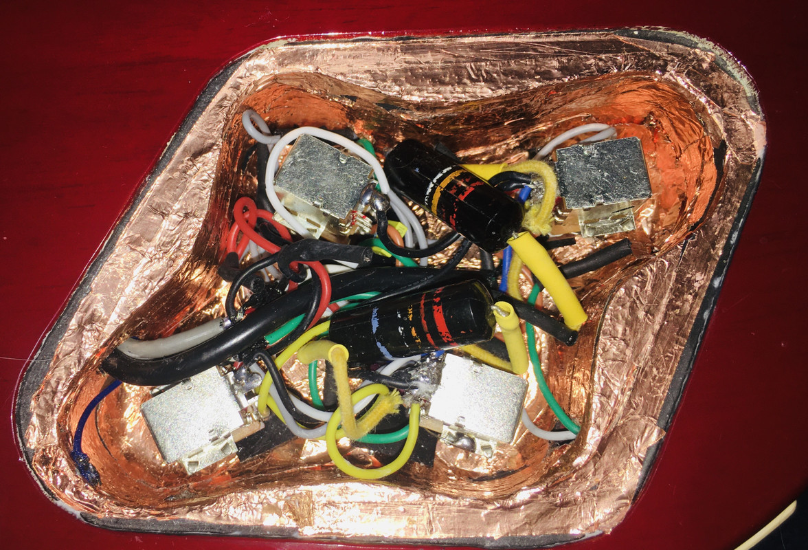 |
|
|
|
Post by newey on Apr 18, 2021 13:15:27 GMT -5
even buy another pigtailed battery connector. That was my first thought, easier just to replace the whole battery connector, and those things can be had cheaply. I bought a whole bag of them (a dozen, maybe?) back whan I was assembling my bigger pedalboard. I reversed the pigtailed connector to connect male-to-female to the battery clip of a couple of pedals that lacked a jack for power input, so that I could then wire them for my one-spot power harness. |
|
|
|
Post by unreg on Apr 18, 2021 20:12:33 GMT -5
Thank you blademaster2, newey, thetragichero! Guess I’ll look for pig-tailed battery connectors; the cord is a bit short now and maybe the positive wire wasn’t soldered greatly. I made a thread in the effects devices forum. |
|
|
|
Post by unreg on Apr 20, 2021 0:51:41 GMT -5
I made a thread in the effects devices forum. DON’T go read that thread bc the soldering worked wonderfully; thank you so much blademaster2 newey thetragichero ashcatlt!  The actual problem was that I tried to test my pedal turning on without plugging a cable into its input TRS jack. 😔 So, that’s why it didn’t work after editing the wiring... I feel foolish. Fx96’s only problem now is that it never turns OFF with the pedal press. Not sure what to do; destroy that thread? It’s quite a lot of learning, but the result is a silly mistake discovered. 😔 |
|


