|
|
Post by thedoc735 on Jul 1, 2020 17:38:27 GMT -5
can anyone verify that this schematic will actually work with 'split' on both pickups, and phase shift on the neck pickup?  |
|
|
|
Post by reTrEaD on Jul 1, 2020 22:10:31 GMT -5
can anyone verify that this schematic will actually work with 'split' on both pickups, and phase shift on the neck pickup? Yes, it will work. btw, this is the source: guitarelectronics.com/2-humbuckers-3-way-lever-switch-1-volume-1-tone-coil-tap-reverse-phase/It isn't necessary to shunt unused coils the way they did so I'd make some changes if I was going to wire my own guitar to get those results. One thing it does well: The Bridge splits to the South coil and the Neck splits to the North coil (which is hum-canceling) when the Neck is in-phase. And the Neck splits to the South coil when the Neck is out-of-phase, which will also hum-cancel with the South coil of the Bridge. Maintaining hum-canceling when possible is high on my list of priorities so I'd say they did fairly well on that part. |
|
|
|
Post by thedoc735 on Jul 1, 2020 22:35:42 GMT -5
deleted to avoid confusion, please go to post #65, thanks!
|
|
|
|
Post by reTrEaD on Jul 1, 2020 23:21:48 GMT -5
Well, in that case, I wish I could get the pickup wire colour coding right, as I've tried two combinations and the circuit doesn't work correctly! I happened stumble across this image:  That suggests Red should be used for hot, White and Green should be tied together as the series link, and Black should be used for ground. But I really can't say for certain it's correct. |
|
|
|
Post by thedoc735 on Jul 2, 2020 1:00:50 GMT -5
deleted to avoid confusion, please go to post #65, thanks!
|
|
|
|
Post by Yogi B on Jul 2, 2020 14:55:30 GMT -5
The green/white link was how it arrived from the factory (o.e.m.), but that doesn't work with the incorporated phase switch. Problem is; I am not getting anything from the neck pickup and it sounds like single coil and phase reverse. split switch acting like kill switch and phase switch not making much difference in either position? No, "in phase" humbucker warm tones! Don't know if you could possibly suggest what's happened here? It would be odd that they would come from the factory wired incorrectly, not out of the realm of possibility, but quite unlikely. Something I noticed when looking up images of the pickups (e.g. the one in the spoiler tag below) they are presented as literal 4-wire pickups, by that I mean that the bare shield wire looks to be pre-soldered and shrinkwrapped to the fourth wire (presumably black in colour beneath the shrinkwrap). For proper operation of the phase switch these wires will need separating, if you have not done so already. Not doing so would somewhat tally with the current problems as you describe them, assuming that there is some alternate connection between the pickup's baseplate and ground, e.g. shielding tape/paint. |
|
|
|
Post by thedoc735 on Jul 3, 2020 6:42:46 GMT -5
deleted to avoid confusion, please go to post #65, thanks!
|
|
|
|
Post by newey on Jul 3, 2020 8:16:08 GMT -5
I suspect the red/green pair are the south screw, and the black/white pair are the north slug. "BUT!" can't determine which is the positive, and which is the negative in each case? With pickups of the same manufacturer, we can assume that both slug coils are the same and that both screw coils are the same. It doesn't matter which one we call "North" or "South", as those designations are arbitrary anyway. A magnet has both North and South poles. If the "south" pole is pointing in one direction, one manufacturer might look at that direction and call the coil "South". Another might look at it the other way and call it "North". In wiring, all we really care about is whether one coil differs from the other. If you had pickups from different manufacturers, you could use a compass to tell one from the other, but since these are a matched set, there really is no need to do so. Likewise with your question of "positive" and "negative", these are arbitrary designations. If we are not coil-splitting, where we would be concerned over whether we are splitting the screw coil or the slug coil (as was discussed above), it doesn't matter which way around we wire a HB, so long as we are consistent between the two pickups. You could wire it as suggested- green and white together, black to "hot" and red to "ground". Or you could wire it "inside out"- with the black and red wired together, white to "hot", green to "ground". The pickups would sound exactly the same either way. Your diagram is correct, so it does seem like a wiring problem, as Guitar ELectronics suggested. |
|
|
|
Post by thedoc735 on Jul 3, 2020 9:36:56 GMT -5
deleted to avoid confusion, please go to post #65, thanks!
|
|
|
|
Post by reTrEaD on Jul 3, 2020 10:36:20 GMT -5
I know the green & red are a pair, and the white & black are also a pair. IF you know this by measuring resistance between pair, okay. If not I suggest going back to square-1 and measuring resistance of the individual pairs with all the connections free from being connected to anything else. You should get a resistance in the ballpark of 5k ohms between any two wires that are a 'pair'. Be absolutely certain about which wires are paired before going any further. I suspect the red/green pair are the south screw, and the black/white pair are the north slug. "BUT!" can't determine which is the positive, and which is the negative in each case? You can determine which pair is for the slugs and which pair is for the screws, as well as the polarity, by performing a " screwdriver pulloff test" If this is a covered HB, put some tape on the face of the HB in the area where the screwdriver will contact. This is to prevent scratching. Set your meter for the lowest scale of DC voltage available. In most cases this it 200mV. IF the Red and Green are a pair, you can connect your meter with some alligator clips to the Red and Green wires. Allow the screwdriver to be pulled toward the screws, then briskly pry it off. Do the same with the screwdriver in the area with the slugs. You might get a small reading when the screwdriver it contacting and being pried off the wrong coil. But the difference in amplitude will make it apparent which coil that pair is connected to. If you get see the (-) sign on your DVM when the screwdriver is pulled off, the Red lead of the meter is connected to the coil wire we'll label as (+). The image below indicates the best way to position the screwdriver (green) and the ways you should avoid (red)  |
|
|
|
Post by thedoc735 on Jul 3, 2020 11:10:50 GMT -5
deleted to avoid confusion, please go to post #65, thanks!
|
|
|
|
Post by reTrEaD on Jul 3, 2020 13:52:29 GMT -5
"If you get see the (-) sign on your DVM when the screwdriver is pulled off, the Red lead of the meter is connected to the coil wire we'll label as (+). , what you read is either wrong or taken out of context. In the italicized text, there is no mention of which direction the screwdriver (or string) is moving. Nearly all pickup manufactures use the following convention: When the string moves toward the pickup, the (+) wire will show a positive voltage with respect to the (-) wire.
When the string moves away from the pickup, the (+) wire will show a negative voltage with respect to the (-) wire. |
|
|
|
Post by thedoc735 on Jul 3, 2020 14:48:14 GMT -5
deleted to avoid confusion, please go to post #65, thanks!
|
|
|
|
Post by thedoc735 on Jul 3, 2020 15:06:31 GMT -5
deleted to avoid confusion, please go to post #65, thanks!
|
|
|
|
Post by thedoc735 on Jul 3, 2020 20:03:22 GMT -5
deleted to avoid confusion, please go to post #65, thanks!
|
|
|
|
Post by newey on Jul 4, 2020 7:15:53 GMT -5
"Problem was; I was not getting anything from the neck pickup and it sounded like single coil and phase reverse. split switch acting like kill switch and phase switch not making much difference in either position?" I am pleased to say (in accordance with the 'newer' above diagram) that I now have: both pickups/single pickups/split on both or either/phase reverse on the neck pickup; "BUT!" still there doesn't sound like there is a traditional warm humbucker tone in any position(?), still sounds a bit phase'y and quack'y with hum? So, what did you change to make this difference? Your revised diagram looks exactly the same as your first one. Or, at least, if there was a difference, I couldn't spot it. It is difficult to do this test with a digital multimeter. It can also be done with a PC with a sound card and a way to input your guitar, as JohnH describes in his thread on the screwdriver test. But I am not following you on why you think this test has anything to do with the problems you are describing. When we split coils, if we split to both north coils, or both south coils, the resulting single-coil combos will not be hum cancelling. If we get one North and one South, it will be hum-cancelling. This is the only difference. So, when you split the coils, do you get hum? Next, split the coils and put the neck OOP. Since this position will not be hum-cancelling, you should hear a bit more noise. If you have less hum when the phase switch is set to OOP, then your coil split switch is selecting two Norths or two Souths. But what you are describing- no "traditional HB sound"- won't depend on the coil split or phase switch anyway. With the phase switch set to "in phase" and with the coil split switch "off", you should get the regular HB sound, if wired correctly. Check to be sure you are getting both coils of each HB when the phase and coil cut switches are "off". If you can't tell by tapping the coils individually, you may need to measure things with your multimeter, by using a cable and measuring the resistances (with all the pots at "10") for the various switch positions. |
|
|
|
Post by Yogi B on Jul 4, 2020 12:04:58 GMT -5
the bare and the black have been separated on both pickups (as per above diagram), the bridge bare & green have now been joined (as per above diagram), the neck pickup 'bare' now remains separate from the coloured wires (as per above diagram). The white and the red wires have now been joined together on both pickups (as per above diagram). Fair enough, now I can be sure to eliminate that as a possibility. Nearly all pickup manufactures use the following convention: When the string moves toward the pickup, the (+) wire will show a positive voltage with respect to the (-) wire.
When the string moves away from the pickup, the (+) wire will show a negative voltage with respect to the (-) wire. I've never even considered that this would be (almost) standardised given that winding direction and magnetic polarity can both be somewhat arbitrarily defined. I am pleased to say (in accordance with the 'newer' above diagram) that I now have: both pickups/single pickups/split on both or either/phase reverse on the neck pickup; "BUT!" still there doesn't sound like there is a traditional warm humbucker tone in any position(?), still sounds a bit phase'y and quack'y with hum? ...how many other combinations could I try? I'm thinking: "3"... swap black/white swap red/green swap both red/green AND black/white Okay now I'm confused. If the coils of each humbucker are currently out-of-phase then swapping either black & white or red & green should put them in phase, however that will put the relative phase of the coils back to what they were originally (as per the stock wiring), albeit with the phase of both coils reversed and coils series 'stacking' reversed. Reversed phase of all the coils will have no discernible affect on tone and 'reverse stacking' of the coils will only affect which coils are selected when splitting. That is, if the slug and screw coils of each humbucker are out of phase with each other now, then they should have been in phase with previous wiring. Whereas, if the previous wiring had the coils of the individual humbuckers out of phase with each other, then the current wiring should have them in phase. I cannot see how both can be true -- and neither does it explain why previously there was no output from the neck pickup or why the split switch killed the output, but now those are fixed. Swapping both red & green and black & white simultaneously ought to have no effect. Also; start = positive; & finish = negative? Neither. If you look at any of the images you've posted that make reference to start & finish you may note that they have one start wire (north) connected to the output (positive) and the other (south) start wire connected to ground (negative). And since both finish wires are in the middle forming the series link, (ignoring the phase switch) splitting the humbucker one way will result in a positive north start wire and negative north finish wire, whereas splitting the other way will result in a positive south finish wire and a negative south start wire. This is intentional. For in phase hum-cancelling you require two coils that are out-of-phase both magnetically and electrically (reverse-wound-reverse-polarity), thus you require one north coil and one south coil, and one clockwise-wound coil and one counter-clockwise-wound coil. In practice however, all coils are usually wound the same way, so in order to get a 'reverse wound' coil its start and finish leads are simply swapped. This causes the start-finish-finish-start pattern (or finish-start-start-finish pattern) of a humbucker with its coils in phase in series. So, what did you change to make this difference? Your revised diagram looks exactly the same as your first one. Or, at least, if there was a difference, I couldn't spot it. Other than subtle colour changes (to some of the red wires) and the purple highlights, snap. thedoc735 doing this might also provide insight as to why we keep talking about pulling the screwdriver off the coil -- but here's an image to illustrate anyhow: The left-hand waveform is the screwdriver being attracted to and hitting the pickup, the right-hand waveform is pulling the screwdriver away. Going from left to right, you can see that the 'attracted to' waveform initially goes positive whereas the 'pulled off' waveform goes negative. You can also clearly see that the 'attracted to' waveform is much more complex or busy, this is probably due to microphonics or bouncing. This complexity is more likely to confuse your multimeter, and thereby more likely to give inconsistent results. It isn't always as extreme as this, but it's almost always true that the 'attracted to' waveform is more complex than the 'pull off' waveform, hence why the latter is preferred. That is assuming, as you go on to say, that they are wired correctly, i.e. those north & south coils are connected in phase. This isn't (or shouldn't) be the case, the way the diagram shows the phase switch to be wired will reverse which coil of the neck selected when OOP. Therefore with both neck & bridge selected and split, both in phase and out of phase ought to be hum-cancelling. |
|
|
|
Post by thedoc735 on Jul 4, 2020 15:22:06 GMT -5
deleted to avoid confusion, please go to post #65, thanks!
|
|
|
|
Post by thedoc735 on Jul 4, 2020 15:56:31 GMT -5
deleted to avoid confusion, please go to post #65, thanks!
|
|
|
|
Post by newey on Jul 5, 2020 8:56:59 GMT -5
I think, doc, that YogiB and I are essentially saying the same things. All of this talk of screwdriver pull-off testing, North or South coils, etc. is only relevant to the question of which coil is being selected when you flip the coil-cut switch.
You indicated that this problem was now solved. I was asking that you verify which coils are in fact active when you split, and whether you hear any hum, but this was just by way of verifying that the problem with the coil-splitting had, in fact, been solved. But assuming that it has been solved, it doesn't have anything to do with your current problem, which you describe as:
So, as a start to trouble-shooting this problem, I asked that you verify which coils are active when you are set to hear the HBs, without phasing or coil splitting. If we verify that both coils of both HBs are active when they should be active, we can then move on in our troubleshooting to consider whether there is a phasing issue- but given that this is a matched set of pickups, there shouldn't be a mismatch if both pickups are wired identically. So, a phase issue is well down the list of possibilities.
The next test, after verifying active coils, would be to plug a cable into your output jack, turn all the knobs to "10", and measure the DC resistance for all switch positions and combinations, and then posting your results. Set your meter to 20K range if it is not auto-ranging. This would tell us whether perhaps one of the pickup coils is dodgy.
|
|
|
|
Post by thedoc735 on Jul 6, 2020 5:19:37 GMT -5
deleted to avoid confusion, please go to post #65, thanks!
|
|
|
|
Post by newey on Jul 6, 2020 6:43:55 GMT -5
doc- We've been speaking of the "screwdriver pull-off test". This is even simpler- the "screwdriver tap test". It can be done with the guitar strung up. Simply plug the guitar into an amp and tap on top of each coil with a screwdriver or other magnetic metallic object. Tap between the strings, bend the string sideways a bit if you have to. You should hear a distinctive "thunk" with a coil that is active. If the paired coil of a HB is not active, you will probably still hear some softer "thunk", just due to transfer of energy from one coil to the other. But it should be much less distinctive. Since you have a coil cut switch, you can play with that to see what an "off" coil should sound like versus one that is "on". Hearing the difference should inform your testing of the full HB position. More precise testing, as I said, can be done with the multimeter. Do the tap test first, and if that doesn't provide any answers, then we'll move on to using the multimeter. The theory of this technique comes from ChrisK, in a thread he originally entitled "Brain scanning through a nostril". He later retitled it "Discerning Strat-type resistances" and later supplemented it with this thread on LP-type (i.e., 2 HB) resistances. This gets a bit "mathy" but don't worry about the calculations, if you get us the readings we can sort out the rest. Basically, you plug a cable into your guitar's output jack and read the resistances by connecting your meter to the tip and sleeve of the cable. But it is much easier if you don't have to hold the meter probes to the cable. If you have an old cable that has a dodgy end and a good plug at the other end (and you're willing to sacrifice it), cut off the dodgy end and strip back the wires from the good plug. You can then use a length of wire with alligator clips to connect to the stripped ends of the sacrificed cable, so as to assure a good connection without holding your meter's probes to the guitar cable. If you do this, test the plug for continuity with your meter first, to be sure the plug's connections are "known good". If you don't have an old cable to sacrifice, you can also buy a 1/4 phono plug with bare wires at the other end from any electronics source. Here is ChrisK's explanation of his method. But again, don't worry too much about the maths. For our purposes, we already know the resistance of the pots (within tolerances), so just get the resistances of each pickup combo with all the pots turned up to "10". guitarnuts2.proboards.com/thread/3194/discerning-lp-type-resistances |
|
|
|
Post by thedoc735 on Jul 7, 2020 15:10:37 GMT -5
deleted to avoid confusion, please go to post #65, thanks!
|
|
|
|
Post by newey on Jul 7, 2020 17:03:36 GMT -5
OK, I assume that the second column is the results of tapping the coils?
The fact that you measure the resistance at 2.05 with both pickups split to SC, and then measure the opposite split-coil setting at 4.24 is odd. Please double-check those measurements. It is also odd that flipping the phase switch seems to eliminate the hum even with both HBs fully operating. I have no way to explain that.
Let's let other weigh in here.
|
|
|
|
Post by thedoc735 on Jul 7, 2020 19:02:30 GMT -5
deleted to avoid confusion, please go to post #65, thanks!
|
|
|
|
Post by thedoc735 on Jul 7, 2020 19:26:24 GMT -5
deleted to avoid confusion, please go to post #65, thanks!
|
|
|
|
Post by thedoc735 on Jul 7, 2020 20:10:25 GMT -5
deleted to avoid confusion, please go to post #65, thanks!
|
|
|
|
Post by thedoc735 on Jul 7, 2020 21:12:55 GMT -5
newey...just a quick thought; as you are somewhat perplexed/surprised by the results of my tap test, perhaps you could take out the results and replace them with what you would expect to see in this chart (what should it look like if everything is functioning as it should be?)? many thanks!
|
|
|
|
Post by thedoc735 on Jul 7, 2020 22:23:00 GMT -5
deleted to avoid confusion, please go to post #65, thanks!
|
|
|
|
Post by newey on Jul 8, 2020 7:09:43 GMT -5
Perhaps I am being unclear, for which I apologize. When I spoke of "tapping" the coils, I meant physically tapping each coil with a screwdriver or metallic object to see if that coil was operating for a given switch setting. I was not referring to the differnce between splitting the coils of a HB versus pickups that feature possible "coil tapping", that is, using only a portion of a coil. My suggestion was that you perform the simpler "coil tap test" first, then proceed to measuring the resistances if the tapping was inconclusive. I was therefore confused when I saw your graphic containing resistance readings in one column and "coil On/coil off" info in the second column. It looked as if you had done both tests simultaneously. So, in the second column, how did you ascertain which coils were on or off for the various switch positions? As for the resistance measurements, your readings show approx. 8KΩ for the neck pickup, and about 4KΩ for each neck coil individually, when split. This is about what we would expect to see for a HB. Understand that meter accuracy varies, and no two pickup coils are ever wound exactly the same, even when done by a machine, so there will always be some variation, plus or minus, in these readings, just as your readings show. But a difference of a few hundredths in these readings won't mean anything. As this is a "matched set" of N and Br pickups, we would expect the bridge pickup to be wound a bit "hotter", and indeed, we see about 8.5 on the bridge full HB. At the end of your chart, however, when both HBs are combined, we see a parallel resistance for both of about 4.15. This, too, is about as expected. However, when we have this: 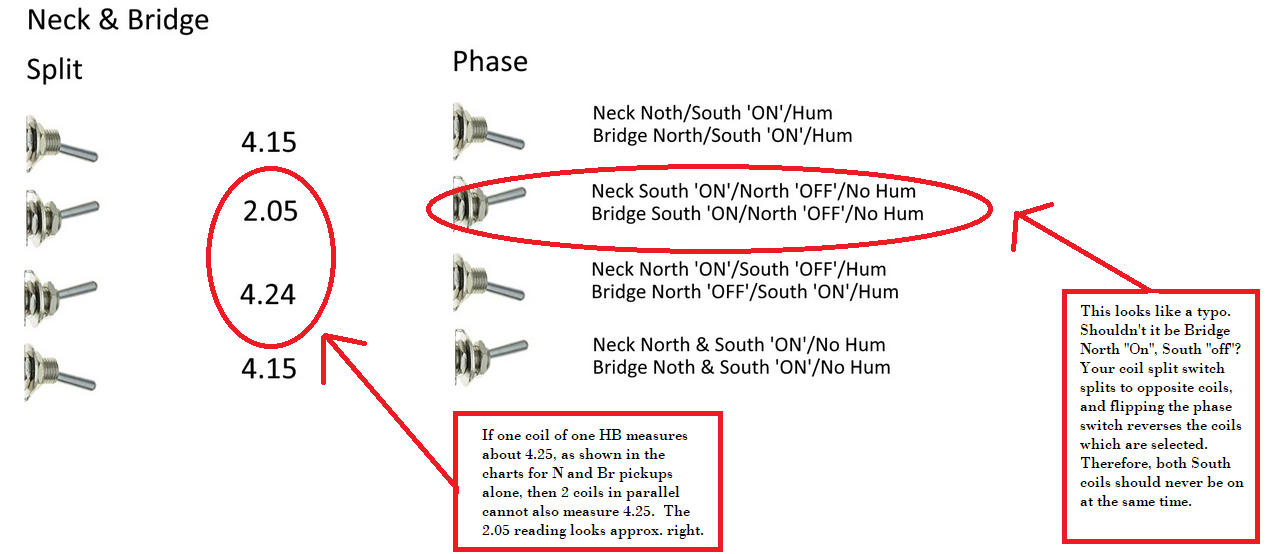 Those are my concerns. If that 4.24 reading is accurate, it suggests only one coil is active in that setting, when 2 coils should be active. This suggests a short at your phase switch (since flipping the phase switch is what makes the difference.) As far as slug vs. screw coils, as per your diagram, with the phase switch "off" (meaning pickups are in phase), the neck pickup splits to the Black/white coil, while the bridge pickup splits to the green/red coil. You are assuming that the North coil is the slug coil and the South is the screw coil based on info from Seymour Duncan, but we don't know for sure because your pickups are not SD. The fact that the wire colors are the same as SD's colors may or may not mean that your magnets are oriented the same as SDs, or that the winding directions are the same. To test this, we had advised the "screwdriver pull-off test" earlier in this thread. But, as I have said several times, your fixation on Start/finish, North versus South coils is misplaced. This information is not relevant to your scheme, and is not any part of the issues you are having. Your scheme selects one North Coil and one South when the pickups are split, and selects the opposite coils when the phase switch is flipped. We don't need to worry or care at all about which is North or South, so long as we get one of each, and get the opposite coils with the phase switch. Likewise, the Start/finish designations are arbitrary, but we needn't worry about htis either, given that both pikups are from the same manufacturer. If you had pickups from different manufacturers, or HB pickups that had very dissimilar coils (like SD's "P-Rails", for example), then we would want to know North/South, Start/Finish, so as to insure the correct phasing (NOT "polarity") and to know which coil was being selected if they differed. But for your purposes here, none of that really matters. |
|


