|
|
Post by frets on Nov 13, 2023 18:21:30 GMT -5
Hi Guys, I posted a diagram probably two years ago and had input from several of you. It is a passive treble bass midrange configuration for a Les Paul. The problem with it is the bass cut. It doesn’t do much at all. It really doesn’t do anything. Im hoping to get some more input on how to remedy this problem. It is the same problem I had before. I’m posting both diagrams. The first is my original. The second is the revision. Im just not happy with the bass cut. I appreciate any ideas.  Revision  |
|
|
|
Post by unreg on Nov 13, 2023 20:03:02 GMT -5
Hi frets, Recently this was posted: Second, in settings where you have all three pickups in parallel, you'll have 4 pots in the circuit which may muddy things up with that setting. I’ve also read ChrisK talking about problem with 4 pots. Do you have 4 pots in circuit, since pot1 is volume, pot2 is treble control, pot3 is bass control, and pot4 is midrange control? If so, then perhaps, having a switch of some sort to exclude a tone pot (?) would “fix” your muddy bass pot?Note: Sry, I don’t know if (?) is possible… just trying an idea. |
|
|
|
Post by mikecg on Nov 14, 2023 10:12:12 GMT -5
Hello frets, I have had a look at your circuit, and here's the results of my simulation:  
As you have not specified what pickups you are using, I have used some generic LP PAF values - not too important as this is primarily an investigation of your bass cut circuit function. The uppermost plot in black, shows the simulated response with all three 'cut' pots at their minimum cut settings, and with the volume pot set for maximum output. I have assumed that the external load consists of 1 Meg in parallel with 470 pF. The green plot shows the effect of your bass cut control at maximum cut - it is working but perhaps, not as effectively as it might? The blue plot shows an improvement that can be had by replacing P3 with a 1 Meg pot, and the red plot shows an even better result that can be had by replacing P3 with a 1 Meg pot, and replacing P1 with a 250k pot. One further thing you can try is to drop the value of your bass cut cap to 1.8 nF - this will produce an upward shift in the bass cut corner frequency - the bass cut effect will shift to a slightly higher 'start' frequency, and will be more noticeable. I hope this helps - |
|
|
|
Post by frets on Nov 14, 2023 15:21:08 GMT -5
Mike, It helps a lot. And your advice is good. Seeing it visually really emphasizes how weak that bass cut is. I did move the bass cut pot to A1M and will try moving the Volume to an A250k. But I’m rethinking my whole approach to it with consideration given to a more literal transposition of the G&L layout. Although it does have a close similarity. But by doing a closer iteration, it may improve the cut. I will just have to experiment with it. The midrange really is just a stand alone pot. I want to improve this as I feel it is a legitimate alternative to the standard Les Paul wiring which I think is a simple and boring. The PTBM configuration would provide enhanced tonal control. I have had some customers interested in the idea. Therefore, I went ahead and did a drop in board for it.  That said, I would be interested in anybody else that may see a problem with my wiring. |
|
|
|
Post by frets on Nov 14, 2023 16:00:59 GMT -5
Mike,
I just swapped out the Volume for a 250k and dropped the 2.2nF to a 1.8nF. I think it is a considerable improvement. I’m now fine with the configuration. The Bass Cut does not have the same level of cut on the G&L configuration, but your recommendations made a discernible improvement. I am happy with it.
Thank you😸
|
|
|
|
Post by mikecg on Nov 14, 2023 16:27:31 GMT -5
Frets,
Good to hear that you have found an acceptable result, and by the way - your drop in LP pcb looks like a neat idea -
|
|
|
|
Post by mikecg on Nov 16, 2023 16:42:13 GMT -5
Mike, I just swapped out the Volume for a 250k and dropped the 2.2nF to a 1.8nF. I think it is a considerable improvement. I’m now fine with the configuration. The Bass Cut does not have the same level of cut on the G&L configuration, but your recommendations made a discernible improvement. I am happy with it. Thank you😸 Hello frets, I have had a closer look at your circuit and have made a few more minor tweaks - if you are interested, I can download a 'tweaked' circuit schematic, and some associated plots. |
|
|
|
Post by frets on Nov 16, 2023 17:36:34 GMT -5
Mike,
I don’t want to make any work for you. But of course I would love to see your schematic. Or, if you don’t want to do all that work, just explaining the changes would work for me. Whatever you decide to do. But I’d feel bad if you spent an inordinate amount of time on it.
I really appreciate anything you can clarify.
|
|
|
|
Post by mikecg on Nov 16, 2023 18:00:16 GMT -5
Ok - Here's the slightly modified schematic, note that I have added a series resistor R9, this improves the mid-cut function, and the R5 damping resistor has been moved to a more effective position. Also, a redundant 1M has been removed:  And here are the plots: This is the bass-cut plot, with P3 stepping from 0, 7.5k, 15k, 30k, 60k, 120k, 240k, 480k, 960k (maximum cut:-15.6 dBV @ 20 Hz) 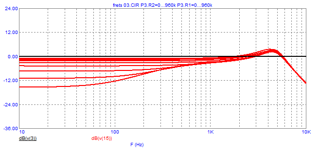 Next up is the mid-cut, with series resonance centred at ~ 650 Hz, and P4 stepping from 0, 7.5k, 15k, 30k, 60k, 120k, 240k, 480k (minimum cut:-1.5 dBV @ 650 Hz) As you can see, turning the pot from 500k to ~ 100k produces a relatively small effect, and most of the 'action' is from 100k to 0. That is why I have suggested using a 250k pot for P4. The downside to using a 250k pot is that it produces a small mid-cut dip when set to 250k (minimum cut) so if a 250k pot is to be used, it would be better if it was a 'no-load' type - otherwise, stick with the 500k standard pot. And see my final plot, below.  And the treble-cut with P2 stepping from 3k, 7.5k, 15k, 30k, 60k, 120k, 240k, 480k (minimum cut: -1.0 dBV @ 300 Hz)  Finally, this plot shows the frequency response with all cuts at minimum and with the P4 no load pot (red curve) and with the P4 500k standard pot (blue curve)  As I said, just a few tweaks - may be worth a try? |
|
|
|
Post by frets on Nov 17, 2023 17:03:22 GMT -5
Wow,
I think that’s a pretty significant improvement. Thank you so much for doing this. It really is helpful.
I think I will have to eliminate the switches though. Guys just don’t like drilling holes in their guitars.
Thank you again. I know it was a lot of work.
|
|
|
|
Post by mikecg on Nov 17, 2023 18:59:38 GMT -5
No problem!
By the way - there are no extra switches or holes required. The switches in the schematic are just simulations of what is already in, or will be in, the guitar. So switch3 and 4 in the schematic do the same electrical job as an ordinary 3 way LP switch, and switch6 is actually just simulating the internal 'no load' function (switch) of the 'no load' 250k mid-cut pot (P4).
So - no extra switches or holes required!
Also note that all the components inside the green box, labelled R10, L5, & C8, are just an attempt to model the Xicor inductor's internal resistance and shunt capacitance. They are 'internal' to the inductor and are not added pcb components. The 'lumped' inductor is just wired between node 10, and ground, as in the previous schematic.
|
|
|
|
Post by frets on Nov 18, 2023 16:39:58 GMT -5
Mike,
That’s good to know.
Just so you know, I’m not great with real schematics; so, I’m going to attempt to translate what you have done into a guitar diagram (I don’t know what else to call it). Then you and the guys can take a look at it and tell me what I have wrong.
I’m really excited about this. I love PTB harnesses and have always wanted the midrange control. And always wanted a harness for a Les Paul.
And the response you are getting is much improved (in my tiny little mind😸). I bet it’s close to what the Strat model produces.
I want to thank you again for doing this. You’re a great addition to the forum😸
|
|
|
|
Post by mikecg on Nov 18, 2023 19:02:15 GMT -5
Frets,
I'm pleased to hear that you are planning to produce an updated wiring diagram - that will be one less chore for me!
Just to recap on the suggested mods:
To improve the bass cut: Swap out the bass cut pot (P3) for 1 Meg, volume pot (P1) for 250 k, and lower bass cut cap to 1.8 nF.
To improve the mid cut: The important mod here is to add the 22 k resistor. With reference to your revised wiring diagram (as shown above), You will need to disconnect the green and cyan wires from the P2 terminal and insert the 22 k resistor, so that one end of the resistor is connected to both the green and cyan wires and the other end of the resistor is connected to the same P2 terminal that the two wires were disconnected from. You can also swap out the mid cut pot (P4) for a 250 k no load type, or if you don't have that type on hand you can probably 'get away' with an ordinary 500 k pot, but the most active adjustment will then be in the last 100 k to 0 range - a tad 'cramped'? That is why I suggest using a 250 k pot. Unfortunately, an ordinary 250 k pot will produce a small, but noticeable mid cut 'droop' even when it is set to 250 k, That is why I have suggested using the no-load version. This type of pot is completely disconnected when the wiper moves to the end of its range, and so there will be no mid cut 'droop' when P4 is at its minimum cut position. And lastly, one end of the 220 k resistor, that you show wired in parallel with the 39 nF mid cut cap, should be moved to a ground connection, so that it is then, in parallel with the Xicor inductor (transformer).
Finally, you show a 1 Meg resistor wired between the wiper and ground of P3, the bass cut pot - I suggest you experiment by removing it - you might win a small boost in the treble response - without it.
|
|
|
|
Post by frets on Nov 19, 2023 15:51:30 GMT -5
Thank you Mike😸😸😸
I am a little confused about the 220k resistor. You are saying to have it in parallel with the transformer running to ground. Do I have the resistor in series with the 39nF cap and then run it through the transformer to ground? Do I wire it between the transformer legs. Or do I run one end from the pot lug directly to ground?
Thank you for your help with this. It sounds easy enough, I just need that resistor clarified.
|
|
|
|
Post by mikecg on Nov 19, 2023 17:37:19 GMT -5
frets, Reference your revised PTB-M wiring diagram: You show the 220k resistor wired between the terminals of the 38 nF cap (i.e. wired in parallel with the cap). You just need to move the end of the resistor that you show connected to the pot terminal to a ground connection, the other end of the resistor stays where it is. When this is done, you will see that the resistor is now wired in parallel with the transformer winding. So, just one end of the 220k resistor to be moved to a ground connection, and the resistor will end up being, as you say - "wired between the transformer legs", or as some say - wired in 'parallel' with the transformer winding.
|
|


