|
|
Post by sumgai on Aug 21, 2006 3:24:59 GMT -5
So after a few months of cursing, I'd come to realize that on some dates, I never touch certain combos, and that three particular combos are strenuous to reach in logical succession. I finally got fed up with it, and re-wired my axe. I'm here to share the results, maybe someone else here will get an "Aha!" moment from it. But for reference purposes, let's review where I'm starting from, with this post/schematic: First Iteration of mods to Strat with an S1 switch. What's changed is that I fixed the hanging hot problem, and re-arranged some of the selections. Since it's silly to swap back and forth between windows/panes/tabs, I'll show the old version of the truth table again, like so: Old Truth Table: S1 Up 1 N 2 N+M 3 M 4 M+B 5 B S1 Down 1 B+Np (out of phase) 2 B+N 3 B+M+N 4 BxN 5 BxNp So I set out to reverse M with B+M+N, in order to put the three "quack" tones all on one side of the S1 switch. Now I can get all three tones without having to flip two switches just to hear what any difference might be. The other thing that bugged me was the constant "double switch diddling" of going from Neck only to Bridge and Neck in parallel - why not just put the B+N combo in Pos 1 when S1 is Down, and make life simple for myself? Why not, indeed. And almost like serendipity, this also led me to fix my "hanging hot" problem without any real effort, something I was gonna do anyway, but it just fell into my lap - honest! <g> The new truth table looks like this: S1 Up 1 N 2 N+M 3 B+M+N 4 M+B 5 B S1 Down 1 B+N 2 B+Np (out of phase) 3 M 4 BxNp 5 BxN And to facilitate that, here's the schematic, in very simple terms:  (There are no parts values shown, that's up to you. And if you wish to rearrange the tone control capacitor, that's OK too.) And now for the piece de resistance..... I've been hung out to dry so often that I'm now gun-shy of submitting anything until I've triple checked it. I've wired up the axe, and it works as advertised. I even made "sub-set" diagrams of each signal path, color coded yet, so that you can follow what's happening for each selection. The colors are pretty obvious, but just for the sake of completeness, the magenta in the two serial combos depicts the "intermediate" signal between the bridge and neck coils - it's neither hot or ground, right?            Let the questions begin! sumgai |
|
|
|
Post by JohnH on Aug 21, 2006 7:06:08 GMT -5
Great diagrams Sumgai. and its built, so it works! (+1) My only question is about the tone control - why is it after the volume? do you prefer it that way?
cheers
John
|
|
|
|
Post by UnklMickey on Aug 21, 2006 10:25:26 GMT -5
...And now for the piece de resistance..... how many ohms in that piece? XD seriously though, this does appear to be a nice piece of work. but i'm gonna wait until i examine it at length, before i sign off on it. i missed a fatal flaw on another thread, and will have to go back there to retract my approval. so, i'm a bit gun-shy, myself. unk |
|
|
|
Post by sumgai on Aug 21, 2006 17:11:39 GMT -5
John,
Thanks for the Exaltation!
It stands to reason that if you affect the tone after the volume control, then the amount of effect should remain the same, no matter how much signal comes through from the volume control, no? We all know that the volume control slightly reduces the treble in a signal (for some portion of the rotation), so does it not make sense to keep to a minimum any interaction between the tone control's reduction of treble, and the volume control's additional reduction?
Besides, most common manufacturer's diagrams show this arrangement, probably for these very reasons, I should think.
But now you've got my curiosity..... why do you ask? ;D
sumgai
|
|
|
|
Post by ChrisK on Aug 21, 2006 20:47:30 GMT -5
Slowly pSpice and see........
|
|
|
|
Post by sumgai on Aug 21, 2006 22:14:00 GMT -5
Chris, Are you saying that practically every guitar maker out there to ever assemble an axe has done it backwards, all these years? I know that in an active setup (most amps), it usually pays to put the volume control after the tone controls. But in such a scenario, the volume control isn't constantly being adjusted, it pretty much stays stationary - not so for a guitar, IME. I just might have to breadboard up a Franenstrat to try this out - I am not going back into my AmDlx again so soon. Fortunately I have the parts with which I can do that, now all I need is the time. (Hah! As if!!) sumgai |
|
|
|
Post by JohnH on Aug 22, 2006 7:56:14 GMT -5
Sumgai - My belief is that the standard configuration is with the tone pot wired on the pickup side of the volume control, rather than after it, as in the standard wiring for Strats, Teles and LPs. In that position, it can interact consitently with the pickups, independednt of where the volume pot is set. With the tone after the volume, I would expect the treble cut to be deeper, when volume is reduced.
John
|
|
|
|
Post by sumgai on Aug 22, 2006 15:34:39 GMT -5
John, You pretty much "forced" me to go back and re-check some of my sources, and sure enough, many, if not most, guitars do install the tone control before the pups. Funny, I never really gave it a second thought.  Should I thank your for the wake-up call? But, for the record, I don't see that the overall tone is so affected by the difference in wiring. The resultant interactions may take place at different points of rotation on the controls, but for all practical purposes, I'm sure that I'm getting the tone out of the guitar that I want, with no more hassle than the ordinary way.  So, other than that, Mrs. Lincoln, how did you enjoy the play? ;D sumgai |
|
|
|
Post by sumgai on Sept 9, 2006 15:08:52 GMT -5
John, OTOH, for some reason I decided to clean up some old junk on the computer this morning (it's raining), so I tripped across some notes and drawings from my Strat AmDlx 2005. You might recall that you asked for a schematic some time ago, you wanted to know what that "special" capacitor did. Well, I drew it up, posted it ( here), and no one blinked. Yet there it is, in all it's glory, the tone controls come after the master volume control. I know I made sham dure that I was getting it right, before I tore it all apart. I'll grant you that this is pretty much the exception, but as I look around, Strats have nearly always been this way. Don't know why, but there we are. BTW, not only am I 'bumping' this (just to keep this thought train on track), but I'm starting a new thread in a few moments, with yet another upgrade for the ol' battle axe. Oh, joy! ;D sumgai |
|
|
|
Post by JohnH on Sept 9, 2006 16:59:28 GMT -5
Sumgai - thats very interesting. I wonder why Fender did that on the AmDix? It could be wired with tone before or after, I dont think it is related to the S1 thing. But as to more typical Strats, do you think that, for example, the GN wiring here is not normal? This shows tone before volume cheers John |
|
|
|
Post by sumgai on Sept 9, 2006 21:58:23 GMT -5
John, I really can't tell what's normal anymore.  Playing just a bit more today, I really need two guitars wired one each way, and play them in an A/B comparison. Already my memory of "tone after volume" has faded. I ascribe this to the similar tonality of each method, that's what struck me the moment I fired up the newest incarnation. "No difference" I said to myself after just two chords. Even after several minutes of futzing around, I still couldn't find any way to tell that one way sounds "better" than the other. I sure wish someone would come up with, and express, a valid reason for putting the tone in front of the volume, other than "that's the way so-and-so always does it". ;D sumgai |
|
|
|
Post by sumgai on Sept 9, 2006 22:16:26 GMT -5
John, I'm still cleaning out crap from Gawd knows when (even if it's no longer raining  , and came across some "before" photos I took prior to modding my current axe. I am no longer convinced that my diagram is absolutely, 100%, without a doubt in the world, correct. I didn't capture the critical area like I'd hoped (and should have), but I've got enough to make me wonder just what the truth is. Short of going out and buying another one of these things, I'll just have to wait for an opportunity to come waltzing through the door.  Take a close look at these, and see if you agree that it's more probable the four poles/sections of the blade switch were tied together, and then fed to the top of the volume pot. (The wiper is clear at the moment, due to the scratchplate's full removal from the guitar body. I simply unsoldered the wire from the terminal. And no, I don't recall if I unsoldered one or two wires, it was almost a year ago.)   This wouldn't stand up as evidence in a court of law, but it does suggest that I may have been (gasp) wrong in locating the tone controls after the volume control. Ah me, what's a poor boy to do.....  sumgai p.s. Now you know what the S1 looks like, and how and where the special cap was mounted. ;D |
|
|
|
Post by JohnH on Sept 10, 2006 1:59:21 GMT -5
Sumgai - The photos need a bit of staring at, but in the meantime here’s some investigation: If the volume or tone or both is at full, then where the tone control is wired makes no difference. The risk however is that, when the tone and volume are both turned down, the tone after volume configuration will get dim and muddy. As Chris suggested further up, this can be demonstrated in PSpice. Take a look at this circuit, which is representing two guitar circuits in parallel, from a single low impedance source in the middle. The one ending up on the right is tone before volume, while the one on the left is volume before tone:  The red and green markers are where the voltage is measured. The tone pots are R5 and R6, shown here turned down to 20k (but say 500k at max), with 0.022uF caps. The volume pots are the pairs R3/R4 and R7/R8, representing a 500k pot, shown here turned down to 20%. C1/R10 and C4/R9 are the cable capacitance and amp input impedance. The pups are medium hot single coils, with 3H inductance and 6k resistance. Now some results, first, tone and volume at full. Both red and green traces are the same  Now keeping the volume at full, turning down the tone to about 5:  Still the traces are the same, since the volume is at full Now turning both tone and volume down to about 5, and a difference is seen:  With both turned down to 2, there is a big difference in the response.  And with volume at 2 and tone 0, a further difference:  According to these results, with tone after volume, when volume is reduced, it causes less clearly defined tone response, with loss of mids, as compared to volume after tone. BTW, my reason for getting into all this is due to a design I’ve been working on with two volumes and a master tone. Very tempting to put the tone after the two volumes in that case, but I was worried about this effect. cheers John |
|
|
|
Post by sumgai on Sept 10, 2006 3:12:13 GMT -5
John,
Nice work! Looks pretty convincing. However.....
The proof is always in the pudding. To my ears, the alleged drop in the mids doesn't show up, or not enough to bother me, anyways. Of course, this could be due to my use of the (stock) tone pot value of 250KΩ, and not 500KΩ. (And the cap is the same as you modeled, a stock 0.022µfd.)
And what's with that "extra" treble signal that isn't being cut, does that mean that the control is not operating properly? Seems to me you've got an interaction going on that is, at this time, unexplained. The tone control is a simple thing, with a nominal 3dB per octave roll off. Yet suddenly the curve has been flattened, noticably so! How'd that happen, I wonder.......
Instead of millivolts, it would be nice if the graph were calibrated in dB.... any chance of making that happen? Please? ;D
sumgai
|
|
|
|
Post by JohnH on Sept 10, 2006 3:26:00 GMT -5
Sumgai - I just went back and added another graph at the end, with tone at zero. I dont know how to plot db on the vertical , but the volts scale is plotted logarithmically, as with db, and x10 in volts is 10db, or 20db in terms of power. Hence the shape of the curve is the same as one plotted in db
The differences are mainly due to how the tone cap is or is not interacting with the pup inductance. With the volume between them, this interaction does not happen unless the volume is high. This is also what explains the peaks which are created. I dont think there anything really mysterious, but it's a bit more complex than just R and C.
John
|
|
|
|
Post by sumgai on Sept 11, 2006 19:01:24 GMT -5
John,
dB versus mV in log.... While these two may present a similar trace, the fact is, there is a dashed line (on the "reticule") that does not easily fit the scale, either in X or Y. Moreover, the X axis is plotted for every power factor (very log-ish), but the Y axis is plotted for twice the power factor (but not log-log). That tends to skew the overall results, I'm sure you'll agree.
Yes, the curve is still gonna be a curve, but I'm still in shock at seeing the curve flatten out so much!
Listen, I'd love to sit and chat about LRC circuitry, but I've suddenly gotten two projects thrust onto my plate, so I've get to get crackin'. ;D More later, as time unfolds...... (and hopefully as life regains some sembalance of normalcy!)
sumgai
|
|
|
|
Post by ChrisK on Sept 11, 2006 19:45:02 GMT -5
Indeed!
The interactions of the tone cap with the pickup LCR circuit creates a hump at resonance.
Shunting your "typical" pickup (which is veeerrrry close to the model that I use for a single coil, although you are missing the inter-winding capacitance across the pickups) with a 1,000 pF cap will cause a peak at about 3 kHz.
Shunting the pickup with a 0.022 uF cap (with the tone turned all the way down) will cause a maximum peak around 700 Hz.
The Fender "Grease Bucket" magical mystical tone dewobbulator circuit essentially eliminates this effect (as well as altering the response).
Note that nothing's free. Any peaking comes at the expense of high frequency output. (Generally equal spectral energy density.)
|
|
|
|
Post by UnklMickey on Sept 11, 2006 21:26:47 GMT -5
...The differences are mainly due to how the tone cap is or is not interacting with the pup inductance.... John, that is true for the hump. the change in slope of the response curve will happen even with a non-reactive source! this is because changing the volume control, will change the resistance in series with the cap. i don't have a pspice program, per se. however, i was able to twist around the TSC to accomplish a tone cut and volume control. 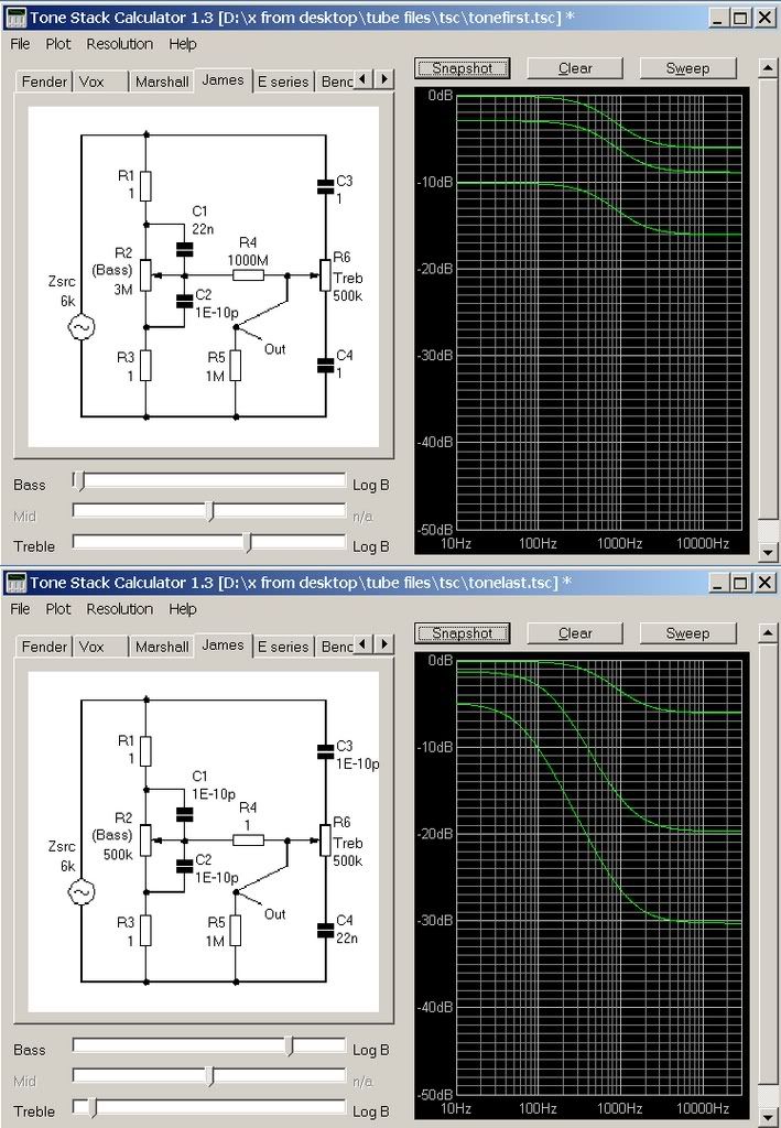 in both examples i adjusted the "tone control" to get a 6dB cut @ 10kHz then i took snapshots with the "volume control" at: 1 -- maximum 2 -- reduced to get -3dB @ 100Hz 2 -- reduced to get -10dB @ 100Hz notice the disparity in the shape of the curves. unk EDIT:i kinda just tossed this out there, without much detail yesterday. following up, the first arrangement uses R6 (treble) as the volume. C3 and C4 are set to 1 Farad (short). R4 is 1 Gohm (open) likewise R1 and R3 are set to 1 ohm (short). C2 is set to 10 -10pF (open) that leaves R2 (bass) and C1 to perform the treble cut duties. to get the -6dB @10k, most of the resistance of R2 is in parallel with C1. since this is nearly 3 Meg, the parallel part mostly negligible. ...................................................................................... the second graph, used R2 (bass) as the volume, and R6 (treble) with C4, as the treble-cut. C3 is open, and we link the circuit with R4 as a short. .................................................................................................. afterward i changed things around. for the "tone first". here's a similar configuration, using R1 and C1 to do the treble-cut. if anyone has a problem with the parallel resistance (10 G ohms), well...........  |
|
|
|
Post by sumgai on Sept 12, 2006 1:20:12 GMT -5
unk, Thanks, that looks much more like how I'd expect a set of traces to appear. Looks like it's time for me to stop jury-rigging lash-ups on the ol' test bench, and get with the program. (pun highly intended!) Chris, you're correct about "hidden" effects of various kinds. I wonder how many more are lurking aboot that we should be modeling in our spice proggies....... sumgai |
|


 Should I thank your for the wake-up call?

 , and came across some "before" photos I took prior to modding my current axe. I am no longer convinced that my diagram is absolutely, 100%, without a doubt in the world, correct.
