|
|
Post by flateric on Mar 2, 2008 18:00:46 GMT -5
I'm putting together a new bass, it's quite an ambitious project for me, a 5-string fanned-fret bass with a 3 band preamp and musicman type single humbucker. Here's a typical 3-band schematic. I want to add an LED to the circuit that will light when the jack is plugged in and act as a battery check.  Trouble is, I have a Neutrik locking jack socket for this, its a stereo unswitched type with 3 lugs - ground, tip and ring. The guitar has a recessed cavity detail on the back (like a Dingwall) to take the exact dimensions of the Neutrik jack, so switching to a standard stereo jack instead is not an option. Can anyone help with the wiring for this please? Can I do it with the NJ3 type of jack I have? If not, then I would rather install a mini toggle switch to turn the battery on/off, rather than not use the neutrik jack in the nice little recess i spent hours chiselling out  Is is simply a case of wiring the LED between the Ring and the Tip of the jack? Thx guys! Oh, here's a shot of the build so far:  |
|
|
|
Post by sumgai on Mar 2, 2008 19:50:33 GMT -5
♭eric, Ya know, I went googling for a suitable instruction page on this topic, and all I found were multiple LED wiring directions. Wassup wi' dat?   So, I guess I'll have to write my own tutorial for you.  In essence, you don't need to worry about the Tip of that jack, the Ring is the only thing of concern to you. You'll want to run a resistor from ground to the Cathode of your LED, and the Anode of that little goodie will go directly to the positive side of the battery. (The Cathode is nearly always the flat side of the LED.) When a plug is inserted, the Ring terminal connects the battery negative to ground, thus turning everything on. For a standard red LED, the value of the resistor can vary from as little as 470Ω up to about 1KΩ. Somewhere in between you'll find a value that gives you the desired brightness. Other colors will likely have a different current requirement, so the resistor values may go up or down from there. Ask for more help, if this is your case. HTH ( Edited to correct a resistor value: starting the range at 390Ω exceeded the maximum current value for most LED's.) |
|
|
|
Post by ashcatlt on Mar 3, 2008 0:09:43 GMT -5
flateric - Doin' it your way might make fuzz, though.
Sumgai - is that in parallel or in series with what's already there?
And, won't the LED likely eat more battery than the circuit itself?
|
|
|
|
Post by sumgai on Mar 3, 2008 2:42:44 GMT -5
ash,
More or less, the described circuitry is across the battery, with the Ring terminal acting as a switch. That places it in parallel with the active module.
And not knowing just how much current the module is rated to draw, I'd have to answer "I dunno". 470Ω across 9 vDC equals 19 point something mA, a hair under the 20mA maximum rating for most LED's. Unfortunately, as soon as the battery starts going downhill, the LED becomes dimmer. There are ways around that, but none so cheap (and easy to understand) as this simple circuit.
sumgai
|
|
|
|
Post by flateric on Mar 3, 2008 4:40:18 GMT -5
So, if I understand correctly, all I have to do is this:  Then select the appropriate resistor value to balance the LEd brightness with the battery drain? |
|
|
|
Post by flateric on Mar 3, 2008 5:59:34 GMT -5
A guy on Talkbass forum said the above would not work, he advised this: 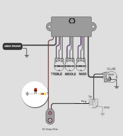 |
|
|
|
Post by sumgai on Mar 3, 2008 13:05:21 GMT -5
♭eric, The second version is correct. The first one simply goes from ground to ...... ground - when the plug is inserted. Not a Good Thing.  BTW, which module are you using in your diagrams (and presumably, in your axe)? ash is right, it'd be nice to know what the current draw is....... Battery drain can be slowed a little bit by using a larger resistor, that's true. However, there's no easy calculation that would tell you, on paper, how bright the LED would be, for a given rate of drain. It's up to your eyes, and your normal playing situations, to determine what's a good brightness level. At that point, I advise that you just let the chips fall where they may, vis-a-vis battery life. Given all else, for just the one LED, I'd estimate that a 9v alkaline battery would last 6 months easily, under most playing circumstances. That's why it'd be nice to know the current requirements of that module, then we could estimate battery life more closely. HTH sumgai |
|
|
|
Post by flateric on Mar 3, 2008 19:02:08 GMT -5
The diagram is off the UK AxesRus guitar parts site, an old favourite of mine, they sell it online as a 2 or 3 band preamp boost/cut - it'll be chinese origin most likely. The one I actually bought is from GFS (guitar fetish pickups) and is very reasonably priced. I predict it will be very close indeed to the diagram above but I have no further info till it arrives with me from the US. AxesRus seem to trade a few GFS stuff in the uk.
I have this urge to run an LED up into the headstock now to light up when the cable is inserted, just for fun but I don't want to disturb the neck as it's been a really great carve for me. The fingerboard is not yet installed but I'd ned some pretty fine wires.
|
|
|
|
Post by newey on Mar 3, 2008 23:28:46 GMT -5
Eric- Well. if you're up for running wires under the fingerboard, I think 2 LEDs flush thru the fingerboard at the 12th fret would be waaaay coooool!  P.S.- We all just get over salivating on your Rick build, and you're building another to-die-for bass? Do you wear a cape with a big "S" on it?  |
|
|
|
Post by flateric on Mar 4, 2008 8:22:22 GMT -5
I do sometimes get caught wearing my pants over my trousers.
|
|
|
|
Post by flateric on Mar 6, 2008 17:08:06 GMT -5
Thx for the input guys, circuit worked fine for the LED, now I need to wire up the pickups.
|
|


