|
|
Post by ChrisK on May 1, 2006 18:11:43 GMT -5
Edited 20060502 New schematic added.This is a setup that used two humbuckers. I've always wanted to do a SD JB/Jazz combo, but wanted the flexibility to realize all coil combinations. I chose an alder Tele body along with a 1 7/8" nut neck for the delivery vehicle. The choice of alder may be too bright, but that's why we invented tone controls. Each pickup has a series/single/parallel switch, and a 4PDT phase toggle to switch all four wires to maintain humbucking configurations in combination w/ the other pickup (of course, when one has both coils engaged and the other has only one, it's at best "half-humbucking"). The basic structure of the switching is as follows: 1. Bridge 2. Special, see below 3. Bridge + Neck 4. Bridge * Neck 5. Neck Special means: Bridge inner/slug coil * (Bridge outer/screw coil + Neck outer/screw coil) * Neck inner/slug coil. [Bic*(Boc+Noc)*Nic]This is realized with reversing the magnet in the neck pickup to have the normal single coil modes be based on both slug or screw coils. There are two phase switches to allow the selection of either pickup to have either its screw or slug coil as the single coil primary, as well as out of phase sounds. The special structure only occurs when both pickups are selected for series. When one is selected for parallel or single coil, it is intended to be in parallel with one coil of the other. The dashed lines indicate some ambiguity on my part. It's a work in progress as I haven't vetted all possible combinations, but it feels "flexibly good". 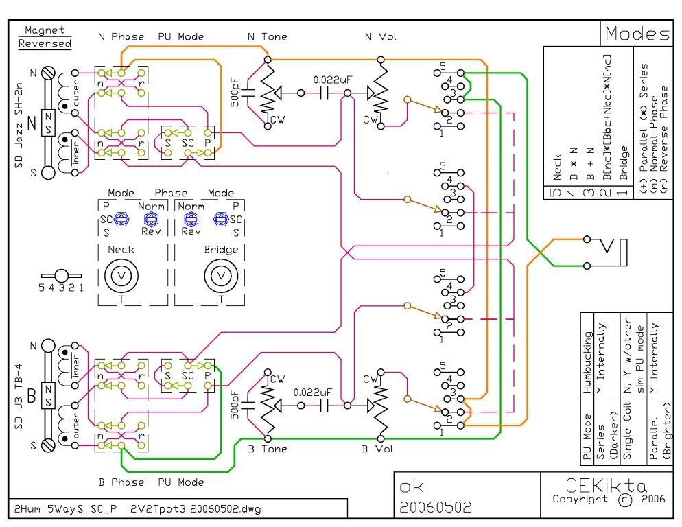 Here are links to the neck (now finished) and body (I bot the tongue oil   ;D). Since this is a wiring design post, I won't clutter it w/ the actual pics. i37.photobucket.com/albums/e84/cekikta/2HB%20Tele/WN35217_8b.jpgi37.photobucket.com/albums/e84/cekikta/2HB%20Tele/WN35217_8a.jpgi37.photobucket.com/albums/e84/cekikta/2HB%20Tele/T1473_12b.jpgi37.photobucket.com/albums/e84/cekikta/2HB%20Tele/T1473_12a.jpg |
|
|
|
Post by CheshireCat on May 2, 2006 2:44:04 GMT -5
What program did you use to create this? |
|
|
|
Post by ChrisK on May 2, 2006 11:39:13 GMT -5
Chesh,
AutoCAD LT, poured as a pdf, resaved as a png in Acrobat, resized to document size in MS Office Picture Manager, and thence rendered as a jpg.
|
|
|
|
Post by vonFrenchie on Jul 18, 2006 11:27:19 GMT -5
When you used the .022 uf capacitor for the tone pots, was that simply out of personal preference? And what is the purpose of the 550 pf capacitors?
|
|
|
|
Post by ChrisK on Jul 18, 2006 21:59:13 GMT -5
0.022uF is generally what I use for humbuckers.
If you run a pSpice emulation, you'll see that the 500pF cap causes a peaking of 5 to 10 dB at around 3kHz. It gives a sort of upper mid "boost" when set to "10".
I do mean boost in a passive circuit. Since the spectral energy density remains constant, the peaking at 3kHz causes a steeper fall-off beyond.
Nothing's free.
|
|


 ;D). Since this is a wiring design post, I won't clutter it w/ the actual pics.

