Post by ChrisK on Aug 8, 2008 19:46:18 GMT -5
NOTE: Edited on 04/08/2012 to display archived images from a new server!
The Passive High-Cut Tone Control
I often see discussions that refer to the passive high-cut tone control used in virtually all passive electric guitars as having characteristics that "pass" frequencies lower than the cutoff frequency and "cut" or attenuate those above said cutoff frequency. I also see where it is posted that the capacitor's impedance (or as often incorrectly called "resistance" or "AC resistance") forms a divider with the tone pot.
Neither of these are accurate. The high-cut RC tone control forms an AC circuit that does form a divider as a function of the complex vector of the RC response (the magnitude of which is equal to (R^2 + xC^2)^0.5 and a phase shift as a function of the cutoff frequency). Using only the capacities reactance (xC = 1/(2PiFC) and the pot only tells the voltage magnitude of the signal at any given frequency, but ignores the tone contribution of the tone circuit (the phase angle) to the tone of the guitar.
Also, the response of this single pole RC circuit is not a wall above which no frequency will pass, but rather a sloped attenuation response that constantly reduces the frequency response as a function of increasing frequency.
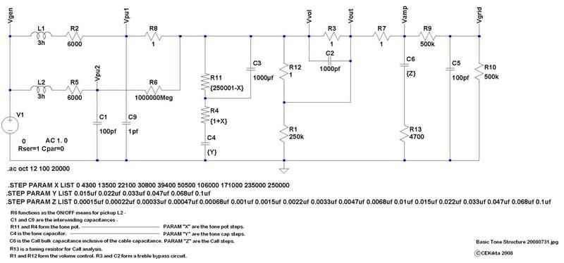
For the examples in this thread, this is the overall simulation circuit;
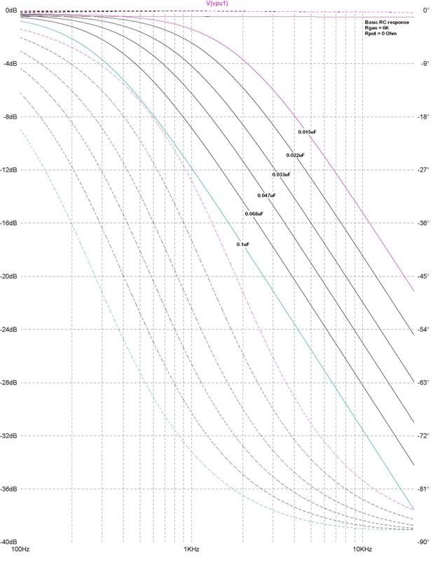
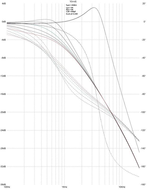
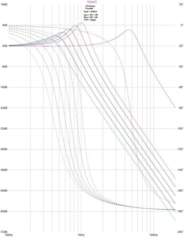
The solid lines relate to the left margin (in dB, which is a logarithmic measure not unlike the Richter scale for earthquakes - for every 20 dB the signal is 10 times larger or smaller in amplitude) and are in Hertz (frequency) along the bottom.
The dotted lines relate to the phase shift response in degrees along the right margin, again as a function of Hertz. One will note that the phase is generally (well actually but it can be difficult to ascertain in detail here) at 90 degrees at the cutoff frequency.
Please note that cutoff frequency DOES NOT MEAN that the signal is "cutoff", but merely indicates by definition the -3 dB (half-power) point in the low pass frequency response curve.
Also note that the left margin units automatically scale as the responses vary in amplitude. Do not scale the graphs or overlay them as the scales are indeed different (sorry).
Additionally note the signal amplitude peaking that occurs and varies with different capacitors and settings on the tone pot.
This is one AC generator with 6K internal resistance driving 6 different values of capacitors to show just the response of said capacitor circuit only. It utilizes none of the intrinsic characteristics of a pickup, but solely indicates the effect of an RC response curve due to a constant voltage excitation over frequency and the interaction between the series driving resistance and the capacitive reactance. Of course, since this is a simple single pole model (6 dB per octave) there is much more to it all, but this gets us started.
For a real-world simulation, the internal inductance of the pickup, its internal inter-winding capacitance, and the total external capacitance including the cable capacitance must be accommodated. Note that while the RC example had a single pole response (6dB per octave), this model, which is an LCR model has a 12dB slope per octave (2 pole).
To show the varying tone response curves at a fixed tone pot setting with the 6 different tone capacitors;
This is one single coil pickup with the 6 capacitors, with 0K series resistance, and only the pickup/cable capacitance. This is "0" on the Strat tone knob dial.
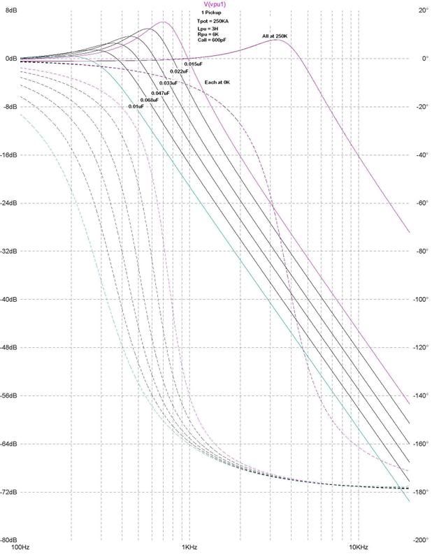
This is one single coil pickup with the 6 capacitors, with 4K3 series resistance, and only the pickup/cable capacitance.This is "1" on the Strat tone knob dial.
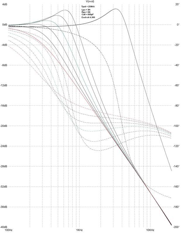
This is one single coil pickup with the 6 capacitors, with 13K5 series resistance, and only the pickup/cable capacitance. This is "2" on the Strat tone knob dial.
This is two single coil pickups in parallel with the 6 capacitors, with 0K series resistance, and only the pickup/cable capacitance. This is "0" on the Strat tone knob dial.
To show the varying tone response curves at a varying tone pot setting with the a fixed tone capacitor. Note the shifted low frequency peaking that occurs when the tone pot is at or near "0". This is the "booming" effect that is intrinsic to every such circuit that can go to zero Ohms. The Fender "Grease Bucket" tone controls on the Highway 1 series eliminate this, however by simply not turning the control below "2", one can generally do this for "free";
This is a single coil pickup with a 250K tone pot and a 0.022 uF tone cap showing "Strat" numbered tone knob responses.

This is a single coil 250K tone pot 0.047 uF tone cap "Strat" tone knob response;
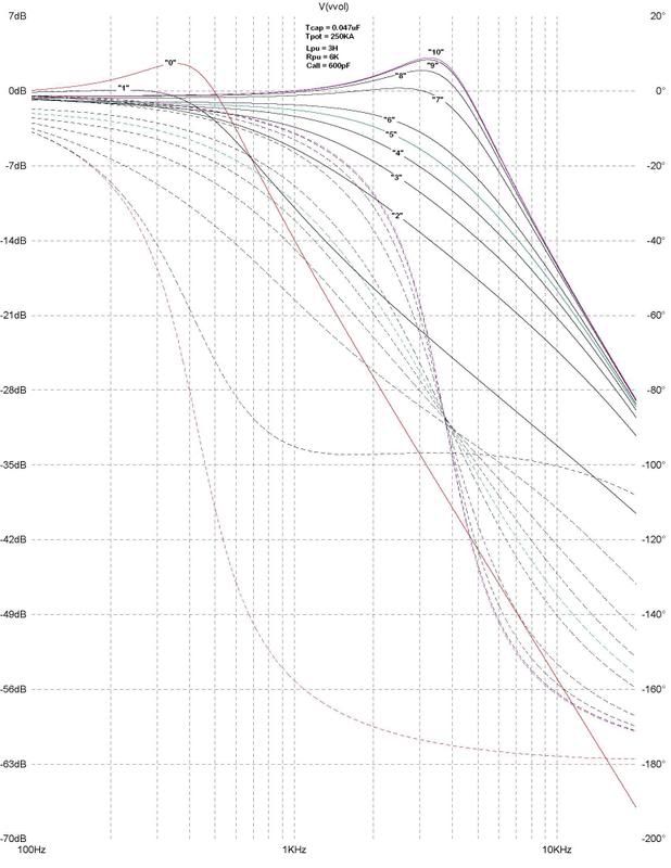
This is a single coil 250K tone pot 0.1 uF tone cap "Strat" tone knob response;

(Sorry, this image was lost before it could be archived.)
Note that while the overall spectral energy of the responses are identical (sans that dissipated in the resistive component characteristics), the spectral/frequency response is not, with voltage peaking (yes, passive voltage gain) evident.
This voltage peaking occurs in a series LC circuit, and, if the circuit "Q" is infinite (ideal reactive components), the voltage approaches this too.
Current peaking occurs in a parallel LC circuit, and, if the circuit "Q" is infinite (ideal reactive components), the current approaches this too.
Fortunately, no component is ideal!
Note that I used this concept in the The Demented TeleBlender wiring for My Proper Telecopy a couple of years ago. S2 modifies the tone control circuit by switching in 0.047 uF, 0.022 uF, or the series combination of capacitance, which is 0.015 uF.
While working on this, I let things get out of hand (why stop at 6 capacitor values) and evaluated the concept of pickup response tuning with simple cheap capacitors and resistors.
Pickup Coil Response Tuning
The Passive High-Cut Tone Control
I often see discussions that refer to the passive high-cut tone control used in virtually all passive electric guitars as having characteristics that "pass" frequencies lower than the cutoff frequency and "cut" or attenuate those above said cutoff frequency. I also see where it is posted that the capacitor's impedance (or as often incorrectly called "resistance" or "AC resistance") forms a divider with the tone pot.
Neither of these are accurate. The high-cut RC tone control forms an AC circuit that does form a divider as a function of the complex vector of the RC response (the magnitude of which is equal to (R^2 + xC^2)^0.5 and a phase shift as a function of the cutoff frequency). Using only the capacities reactance (xC = 1/(2PiFC) and the pot only tells the voltage magnitude of the signal at any given frequency, but ignores the tone contribution of the tone circuit (the phase angle) to the tone of the guitar.
Also, the response of this single pole RC circuit is not a wall above which no frequency will pass, but rather a sloped attenuation response that constantly reduces the frequency response as a function of increasing frequency.
For the examples in this thread, this is the overall simulation circuit;

The solid lines relate to the left margin (in dB, which is a logarithmic measure not unlike the Richter scale for earthquakes - for every 20 dB the signal is 10 times larger or smaller in amplitude) and are in Hertz (frequency) along the bottom.
The dotted lines relate to the phase shift response in degrees along the right margin, again as a function of Hertz. One will note that the phase is generally (well actually but it can be difficult to ascertain in detail here) at 90 degrees at the cutoff frequency.
Please note that cutoff frequency DOES NOT MEAN that the signal is "cutoff", but merely indicates by definition the -3 dB (half-power) point in the low pass frequency response curve.
Also note that the left margin units automatically scale as the responses vary in amplitude. Do not scale the graphs or overlay them as the scales are indeed different (sorry).
Additionally note the signal amplitude peaking that occurs and varies with different capacitors and settings on the tone pot.
This is one AC generator with 6K internal resistance driving 6 different values of capacitors to show just the response of said capacitor circuit only. It utilizes none of the intrinsic characteristics of a pickup, but solely indicates the effect of an RC response curve due to a constant voltage excitation over frequency and the interaction between the series driving resistance and the capacitive reactance. Of course, since this is a simple single pole model (6 dB per octave) there is much more to it all, but this gets us started.

For a real-world simulation, the internal inductance of the pickup, its internal inter-winding capacitance, and the total external capacitance including the cable capacitance must be accommodated. Note that while the RC example had a single pole response (6dB per octave), this model, which is an LCR model has a 12dB slope per octave (2 pole).
To show the varying tone response curves at a fixed tone pot setting with the 6 different tone capacitors;
This is one single coil pickup with the 6 capacitors, with 0K series resistance, and only the pickup/cable capacitance. This is "0" on the Strat tone knob dial.

This is one single coil pickup with the 6 capacitors, with 4K3 series resistance, and only the pickup/cable capacitance.This is "1" on the Strat tone knob dial.

This is one single coil pickup with the 6 capacitors, with 13K5 series resistance, and only the pickup/cable capacitance. This is "2" on the Strat tone knob dial.

This is two single coil pickups in parallel with the 6 capacitors, with 0K series resistance, and only the pickup/cable capacitance. This is "0" on the Strat tone knob dial.

To show the varying tone response curves at a varying tone pot setting with the a fixed tone capacitor. Note the shifted low frequency peaking that occurs when the tone pot is at or near "0". This is the "booming" effect that is intrinsic to every such circuit that can go to zero Ohms. The Fender "Grease Bucket" tone controls on the Highway 1 series eliminate this, however by simply not turning the control below "2", one can generally do this for "free";

This is a single coil pickup with a 250K tone pot and a 0.022 uF tone cap showing "Strat" numbered tone knob responses.

This is a single coil 250K tone pot 0.047 uF tone cap "Strat" tone knob response;

This is a single coil 250K tone pot 0.1 uF tone cap "Strat" tone knob response;

(Sorry, this image was lost before it could be archived.)
Note that while the overall spectral energy of the responses are identical (sans that dissipated in the resistive component characteristics), the spectral/frequency response is not, with voltage peaking (yes, passive voltage gain) evident.
This voltage peaking occurs in a series LC circuit, and, if the circuit "Q" is infinite (ideal reactive components), the voltage approaches this too.
Current peaking occurs in a parallel LC circuit, and, if the circuit "Q" is infinite (ideal reactive components), the current approaches this too.
Fortunately, no component is ideal!
Note that I used this concept in the The Demented TeleBlender wiring for My Proper Telecopy a couple of years ago. S2 modifies the tone control circuit by switching in 0.047 uF, 0.022 uF, or the series combination of capacitance, which is 0.015 uF.
While working on this, I let things get out of hand (why stop at 6 capacitor values) and evaluated the concept of pickup response tuning with simple cheap capacitors and resistors.
Pickup Coil Response Tuning


