Post by JohnH on Jan 31, 2006 23:42:42 GMT -5
Here is a design for converting an LP or SG style guitar, to provide a much greater range of tones. The design features a range of tones from each pickup, combinations between pups in series or parallel, independent volume controls and an active buffer. I have built this into a Cort LP, and it is now my favorite guitar. The core of it came about through a discussion with Runewalker on the Tonemonster thread. I would never have got here without treading that path.
I’ll first describe it as I have built it, then discuss a few possible variations. There are five main ideas that went into this guitar that I would like to share, which can mostly be applied separately and adapted to other designs:
• Converting two-conductor humbucker to four-conductor wiring
• Using a rotary switch to control the tone of each pickup, to give a selection of coil selection options for each
• How to combine two such pickups to maximize hum-canceling, both in-phase and out of phase
• Series and parallel wiring of pickups, with two independent volume controls that work consistently in each mode
• Use of an active buffer to maintain high-end clarity, and as apart of making the independent volume controls fully effective.
Four conductor wiring
Before thinking about coil wiring options for humbuckers, you need to get separate wires from each end of each coil, plus a screen wire. Often on inexpensive guitars (and some expensive ones), only two are provided. This means replacing the pickups, or converting them. If the pickups are open-coil, and given great care, this conversion is possible. To read about this, take a look at Wolf’s explanation of the theory:
www.1728.com/guitar1a.htm
Here is my page showing how it worked for this guitar, with photos:
www.geocities.ws/guitarcircuits/fourconductor/fourconductor.html
Schematic
Here is the schematic:

Rotary Switches to control pickup tone
The normal tone controls were omitted because I don’t use them. Instead, the rotary switches S2 and S3 provide far more powerful control of tone on each pickup. A basic Hb is capable of six coil configurations, being each single coil, plus in or out of phase, in series or parallel. I went for five out of the six, eliminating parallel out-of-phase which has a thin/weak sound. The switching for these therefore needed a 5 position switch for each pup. Three poles create the basic coil configurations.
Most rotaries do not have this many lugs, but 4P5T switches are available from Mouser, which were discovered by Runewalker. That left a spare pole, and on the schematic you can see that it is used on the neck pup only, and it avoids a partially disconnected ‘hanging’ coil (could act to pick up interference), in system-series mode, when the neck has just one of the coils selected.
Hum Canceling
The series and parallel in-phase settings of each pup are hum canceling, while the single coil and coils out-of-phase settings are not. However, by arranging the coils on the neck and bridge pups with opposite positions for North and South, combinations between the two can be made mostly hum canceling even with single coils etc. The idea is that when the bridge pup hums, it always hums with , lets say, ‘positive’ hum, and the neck always produces the opposite ‘negative’ hum. Hence any combination of single coils or out-of-phase settings between pickups cancels hum, at least nearly. To do this, the upper coils in the schematic (I’ve called them ‘Coil 1’) are reversed when selected alone. This also gives you hum-canceling out-of-phase combos between pups. This is a good sound, not as thin as a pickup out-of-phase with itself, more middle sounding.
A result that is not obvious is that one pup with two coils out-of-phase with itself, combined in parallel with another single coil, is also hum canceling.
Here’s my page on coil arrangements for hum-canceling:
www.geocities.ws/guitarcircuits/cancelhum/cancelhum.html
Series / Parallel Switching
Switch S4 puts the pickups into series or parallel (S/P) mode. Usually this is done with a two pole toggle or push/pull switch. When there is also a normal three position selector switch, (S3 on this design), it causes issues with how the 3-position and S/P switch interact. On ‘Jimmy Page’ type designs, the S/P only works properly in series if the 3-way is also in a certain position. I added another pole to S4, and it now completely bypasses S3 when in series mode. So a setting of one or both pups in parallel can be moved to full series with just S4, without needing to move S3.
Independent volume controls
Making these work in series and parallel modes was a brain scratcher. Traditional wiring of two volume controls on an LP works fine when both are at or near max, but if one volume is reduced towards zero, it also fades down the other pup. This is often alleviated by reverse wiring the volumes, with the moving ‘wiper’ connections towards the pups, and the outer connections to the output. I was not happy with that in this case however. At low volume, it causes the pickups to be shunted by a low resistance, and puts a large resistance in series. Both of these could spoil the tone.
For this design, I used the traditional volume pot arrangement, but with a separating resistor (56k) on each pot output. The resistors prevent the interaction which causes one volume to fade both pups. This works in conjunction with a buffer circuit, without which it would also cause tone loss, caused by interaction with the cable to the amp.
There is also a cap and 100k resistor on each volume control. These are as often used for ‘treble bleed’. They also smooth the response of the volume control. In theory, a treble bleed cap should not be needed with a buffer circuit, but I found it sounded better to have them. Also, the cap is a relatively large 3.3nF, again chosen by ear. So with other pups, different values may be better.
Buffer Circuit
This is uses a single JFET transistor to provide a consistent low impedance output. This allows the guitar to drive any sensible combination of amps and effects, and also to be unaffected by loss of tone and interference due to cables. On the input side, it provides a consistent high impedance input, to preserve the full tonal range of the pickups. The result is a more consistent and punchier sound. It is also the key to allowing the independent volume controls, with those separating resistors, to function without affecting the tone.
The circuit is very small and extremely low current – only 50 micro-amps. So with normal use, a battery should outlast its shelf life, or it could run continuously for well over a year. It functions as a simple ‘source follower’, in which the voltage at the low impedance output follows that of its high impedance input. It does not provide gain, but there are other equally simple ways of configuring a JFET, to also provide some gain if that is wanted.
The layout and installation of the buffer is shown below - see 'Construction'
One more capacitor
This was the last addition to the design (so far), and was an interesting result of listening to the sounds.
Having got the guitar working, the first impression was a great increase in brightness and clarity, along with many variations in tone. Further listening showed that the buffer and volume control arrangement was so effective in keeping elements independent that some of the electrical interactions between pups with each other, and with the cable, which in fact cause some mellowing of the tonal character were being lost. Hence the sounds were being differentiated by their coil positions and phasing, but not by their different electrical characteristics.
Series settings normally sound mellower than parallel, due to their greater inductance and resistance. But in this case, although there was a volume difference, the tones were almost the same if the same coils were active in S and P.
So there is an extra 1.5nF capacitor, which engages only in the system series settings. This allows the parallel and single pup settings to pursue maximum clarity and brightness, while the system-series ones have the fuller warmer sound that we expect from an LP. Warmer versions of the single pups are available with system series engaged, and one pup turned down.
Construction
This is the overall wiring diagram as built:
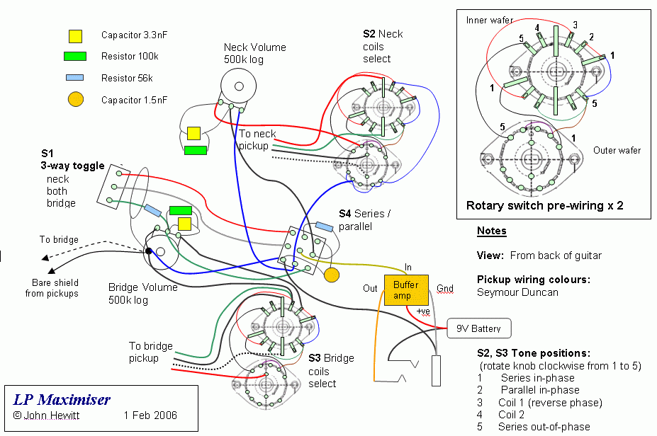
I have adjusted the wire colours to Seymour Duncan, although my own pup conversion used different colours..
Those large rotaries just fitted in the cavity, and have a slightly longer than normal shaft and hence could be fitted without further routing. The guitar has a 40mm thick body, a bit less than a real LP, with 6mm thickness at the controls. The basic wiring of each rotary is identical, and that work can be done away from the guitar.
The buffer is on its own small circuit board. Here it is with its installation (wrapped in electrical tape). It is wired near the jack socket, which is a stereo socket such that the power is engaged when a mono jack plug is inserted.
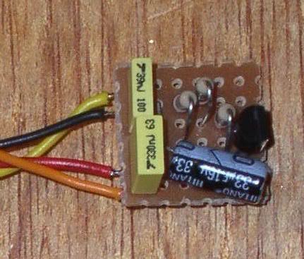
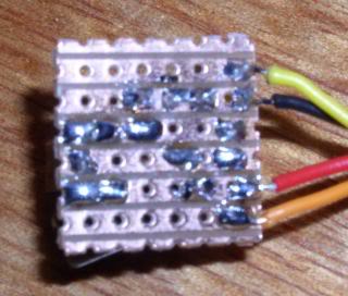

The following shows the layout used for the buffer board, as constructed on a 0.7" x 0.7" piece of Veroboard (Stripboard). The copper strips are on the back, see photo above:
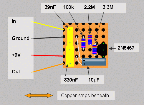
Here is a completed wiring photo. It looks complex, but building it was not too bad. Most of the complication was around the rotaries which were done first.

Here is the front view. Chunkier knobs were added to the rotaries. You can also see the S/P toggle switch, which was the only drilling needed.


Results
Lots to play with here. In addition to the standard humbucker settings, single coils in series, in or out-of-phase are a great addition. Two Hbs in series is LOUD – and a great jazz tone. The mixing of the pups is very responsive with the buffer and volume controls, without the muddying which is sometimes noticed. Hence combos such as full bridge Hb, with about 20% of neck have a character of their own. There is plenty of ‘zing’ available with the various options.
Variations
If I did this again – I believe that not much would be lost with four options per pup instead of five. This would involve losing one SC option at the neck, and the out-of-phase option at the bridge. This would allow a more standard, and much smaller 3P4T rotary to be used for S2 and S3, and still without any ‘coil hanging’ issues. There would still be the full range of sounds, just a few less versions. I will post a schematic of this if anyone wants one.
It is easy to change the order of the pup selections. My intention was to move in order of overall brightness. With the full 5-position switches I would swap the positions of settings 3 and 4, so that with combos between pups, all the in-phase combos happen first.
I have no regrets with omitting the tone controls, there is plenty of variation here. But if wanted, they could be added, either a single master, or two separate ones. Seeing how the circuit reacted to that extra small cap, I think a ‘varitone’ style, with several switched capacitors, would be very interesting.
The buffer could have a ‘boost’ function quite easily.
Conclusion
Thanks for reading this. This design contains everything I know (so far) about guitar wiring. Please post any comments below and I’ll update this post as appropriate.
And please add more designs to this section!
I’ll first describe it as I have built it, then discuss a few possible variations. There are five main ideas that went into this guitar that I would like to share, which can mostly be applied separately and adapted to other designs:
• Converting two-conductor humbucker to four-conductor wiring
• Using a rotary switch to control the tone of each pickup, to give a selection of coil selection options for each
• How to combine two such pickups to maximize hum-canceling, both in-phase and out of phase
• Series and parallel wiring of pickups, with two independent volume controls that work consistently in each mode
• Use of an active buffer to maintain high-end clarity, and as apart of making the independent volume controls fully effective.
Four conductor wiring
Before thinking about coil wiring options for humbuckers, you need to get separate wires from each end of each coil, plus a screen wire. Often on inexpensive guitars (and some expensive ones), only two are provided. This means replacing the pickups, or converting them. If the pickups are open-coil, and given great care, this conversion is possible. To read about this, take a look at Wolf’s explanation of the theory:
www.1728.com/guitar1a.htm
Here is my page showing how it worked for this guitar, with photos:
www.geocities.ws/guitarcircuits/fourconductor/fourconductor.html
Schematic
Here is the schematic:

Rotary Switches to control pickup tone
The normal tone controls were omitted because I don’t use them. Instead, the rotary switches S2 and S3 provide far more powerful control of tone on each pickup. A basic Hb is capable of six coil configurations, being each single coil, plus in or out of phase, in series or parallel. I went for five out of the six, eliminating parallel out-of-phase which has a thin/weak sound. The switching for these therefore needed a 5 position switch for each pup. Three poles create the basic coil configurations.
Most rotaries do not have this many lugs, but 4P5T switches are available from Mouser, which were discovered by Runewalker. That left a spare pole, and on the schematic you can see that it is used on the neck pup only, and it avoids a partially disconnected ‘hanging’ coil (could act to pick up interference), in system-series mode, when the neck has just one of the coils selected.
Hum Canceling
The series and parallel in-phase settings of each pup are hum canceling, while the single coil and coils out-of-phase settings are not. However, by arranging the coils on the neck and bridge pups with opposite positions for North and South, combinations between the two can be made mostly hum canceling even with single coils etc. The idea is that when the bridge pup hums, it always hums with , lets say, ‘positive’ hum, and the neck always produces the opposite ‘negative’ hum. Hence any combination of single coils or out-of-phase settings between pickups cancels hum, at least nearly. To do this, the upper coils in the schematic (I’ve called them ‘Coil 1’) are reversed when selected alone. This also gives you hum-canceling out-of-phase combos between pups. This is a good sound, not as thin as a pickup out-of-phase with itself, more middle sounding.
A result that is not obvious is that one pup with two coils out-of-phase with itself, combined in parallel with another single coil, is also hum canceling.
Here’s my page on coil arrangements for hum-canceling:
www.geocities.ws/guitarcircuits/cancelhum/cancelhum.html
Series / Parallel Switching
Switch S4 puts the pickups into series or parallel (S/P) mode. Usually this is done with a two pole toggle or push/pull switch. When there is also a normal three position selector switch, (S3 on this design), it causes issues with how the 3-position and S/P switch interact. On ‘Jimmy Page’ type designs, the S/P only works properly in series if the 3-way is also in a certain position. I added another pole to S4, and it now completely bypasses S3 when in series mode. So a setting of one or both pups in parallel can be moved to full series with just S4, without needing to move S3.
Independent volume controls
Making these work in series and parallel modes was a brain scratcher. Traditional wiring of two volume controls on an LP works fine when both are at or near max, but if one volume is reduced towards zero, it also fades down the other pup. This is often alleviated by reverse wiring the volumes, with the moving ‘wiper’ connections towards the pups, and the outer connections to the output. I was not happy with that in this case however. At low volume, it causes the pickups to be shunted by a low resistance, and puts a large resistance in series. Both of these could spoil the tone.
For this design, I used the traditional volume pot arrangement, but with a separating resistor (56k) on each pot output. The resistors prevent the interaction which causes one volume to fade both pups. This works in conjunction with a buffer circuit, without which it would also cause tone loss, caused by interaction with the cable to the amp.
There is also a cap and 100k resistor on each volume control. These are as often used for ‘treble bleed’. They also smooth the response of the volume control. In theory, a treble bleed cap should not be needed with a buffer circuit, but I found it sounded better to have them. Also, the cap is a relatively large 3.3nF, again chosen by ear. So with other pups, different values may be better.
Buffer Circuit
This is uses a single JFET transistor to provide a consistent low impedance output. This allows the guitar to drive any sensible combination of amps and effects, and also to be unaffected by loss of tone and interference due to cables. On the input side, it provides a consistent high impedance input, to preserve the full tonal range of the pickups. The result is a more consistent and punchier sound. It is also the key to allowing the independent volume controls, with those separating resistors, to function without affecting the tone.
The circuit is very small and extremely low current – only 50 micro-amps. So with normal use, a battery should outlast its shelf life, or it could run continuously for well over a year. It functions as a simple ‘source follower’, in which the voltage at the low impedance output follows that of its high impedance input. It does not provide gain, but there are other equally simple ways of configuring a JFET, to also provide some gain if that is wanted.
The layout and installation of the buffer is shown below - see 'Construction'
One more capacitor
This was the last addition to the design (so far), and was an interesting result of listening to the sounds.
Having got the guitar working, the first impression was a great increase in brightness and clarity, along with many variations in tone. Further listening showed that the buffer and volume control arrangement was so effective in keeping elements independent that some of the electrical interactions between pups with each other, and with the cable, which in fact cause some mellowing of the tonal character were being lost. Hence the sounds were being differentiated by their coil positions and phasing, but not by their different electrical characteristics.
Series settings normally sound mellower than parallel, due to their greater inductance and resistance. But in this case, although there was a volume difference, the tones were almost the same if the same coils were active in S and P.
So there is an extra 1.5nF capacitor, which engages only in the system series settings. This allows the parallel and single pup settings to pursue maximum clarity and brightness, while the system-series ones have the fuller warmer sound that we expect from an LP. Warmer versions of the single pups are available with system series engaged, and one pup turned down.
Construction
This is the overall wiring diagram as built:

I have adjusted the wire colours to Seymour Duncan, although my own pup conversion used different colours..
Those large rotaries just fitted in the cavity, and have a slightly longer than normal shaft and hence could be fitted without further routing. The guitar has a 40mm thick body, a bit less than a real LP, with 6mm thickness at the controls. The basic wiring of each rotary is identical, and that work can be done away from the guitar.
The buffer is on its own small circuit board. Here it is with its installation (wrapped in electrical tape). It is wired near the jack socket, which is a stereo socket such that the power is engaged when a mono jack plug is inserted.


The following shows the layout used for the buffer board, as constructed on a 0.7" x 0.7" piece of Veroboard (Stripboard). The copper strips are on the back, see photo above:

Here is a completed wiring photo. It looks complex, but building it was not too bad. Most of the complication was around the rotaries which were done first.

Here is the front view. Chunkier knobs were added to the rotaries. You can also see the S/P toggle switch, which was the only drilling needed.


Results
Lots to play with here. In addition to the standard humbucker settings, single coils in series, in or out-of-phase are a great addition. Two Hbs in series is LOUD – and a great jazz tone. The mixing of the pups is very responsive with the buffer and volume controls, without the muddying which is sometimes noticed. Hence combos such as full bridge Hb, with about 20% of neck have a character of their own. There is plenty of ‘zing’ available with the various options.
Variations
If I did this again – I believe that not much would be lost with four options per pup instead of five. This would involve losing one SC option at the neck, and the out-of-phase option at the bridge. This would allow a more standard, and much smaller 3P4T rotary to be used for S2 and S3, and still without any ‘coil hanging’ issues. There would still be the full range of sounds, just a few less versions. I will post a schematic of this if anyone wants one.
It is easy to change the order of the pup selections. My intention was to move in order of overall brightness. With the full 5-position switches I would swap the positions of settings 3 and 4, so that with combos between pups, all the in-phase combos happen first.
I have no regrets with omitting the tone controls, there is plenty of variation here. But if wanted, they could be added, either a single master, or two separate ones. Seeing how the circuit reacted to that extra small cap, I think a ‘varitone’ style, with several switched capacitors, would be very interesting.
The buffer could have a ‘boost’ function quite easily.
Conclusion
Thanks for reading this. This design contains everything I know (so far) about guitar wiring. Please post any comments below and I’ll update this post as appropriate.
And please add more designs to this section!


