|
|
Post by flateric on Feb 7, 2010 12:43:29 GMT -5
The last modded tubescreamer pedal was a great success. I wanted to add a rotary switch to change between 6 different types of diode clipping to change the overdrive characteristics. I came up with this crude perfboard sketch, now I reckon there should be a much more economical way of doing this!  I have a rotary 6 way 2pole switch to connect in. Any suggestions? |
|
|
|
Post by ashcatlt on Feb 7, 2010 13:58:50 GMT -5
Links to the schematic might help...
These diodes are in the feedback loop for the opamp, no? The switching should be pretty straightforward, I think. Input to one common, output to the other. The wires from your diode board go to to corresponding lugs on either side of the switch, and you're done.
One concern I have, though. If you've got break-before-make (non-shorting) type switch, I think it will leave the feedback path open for a split second while switching. Seems like this would cause the opamp to go to maximum gain during that brief period. I think that's likely to cause a nasty loud popping noise.
I have a similar thing I was going to do on the Rat clone whose parts have been sitting around here for a few years. I was going to use two 5-way rotaries to provide either/or/series/parallel combinations of si and LEDs on either side. One day I may even finish wiring it...
|
|
|
|
Post by flateric on Feb 7, 2010 15:37:22 GMT -5
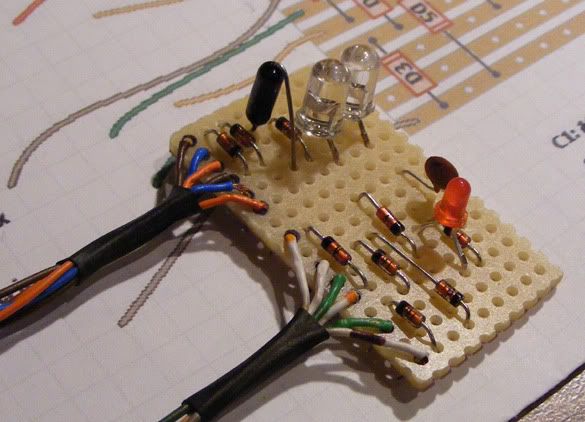 Quick construction on perfboard. I'm wiring in via the diode clipping pair on the TS808 circuit posted up at DIYstompbox.com |
|
|
|
Post by sumgai on Feb 8, 2010 0:05:41 GMT -5
ash,
Actually, all that ♭eric needs to do is leave all the diodes in the circuit all the time (three in series, in each direction), and simply short the desired ones in order to derive more, or less, action. Think in terms of how wolf makes his "series dominant" combinations, as opposed to how the rest of us make "parallel dominant" combos.
This presumes, of course, that the diode strings are in series with the feedback resistor, the usual arrangement.
One might also compensate for level differences by using the same rotary switch to select various values of that feedback resistor to suit one's needs.
HTH
sumgai
|
|
|
|
Post by flateric on Feb 8, 2010 7:02:52 GMT -5
Ahh, a couple of interesting ideas there sir, thx for the input;) Off to ponder...
|
|
|
|
Post by flateric on Feb 8, 2010 8:23:26 GMT -5
This should be a much simpler arrangement: 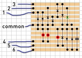 |
|
|
|
Post by flateric on Feb 10, 2010 17:14:10 GMT -5
Here's the final item using the clipping module. 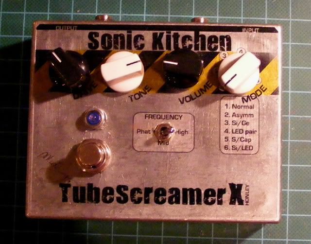 Sonic Kitchen is a Tubescreamer (SRV Special, ex maxxon) circuit with the clipping module added to replace the original two side-by-side diodes, and with an extra input cap on a mini toggle switch which combines a 0.47uF and a 0.047uF (the original) cap. The bigger cap gives a big extension to the bass range making for some dark grungy overdrive also suitable as a Bass guitar distortion pedal. The clipping switch works nicely, theres some subtle differences to the distortion characteristics trying out the different modes. A couple of sweet smooth creamy overdrives on the asymmetric, the Ge/Si mix and the smoothing cap setting, as well as some much higher gain, raw distortion tones using the LED settings. Basically 6 overdrives in one, with a huge tonal range extension built in. The ultimate tubescreamer! |
|
|
|
Post by ashcatlt on Feb 10, 2010 21:53:30 GMT -5
So...whadja end up doing for that mode switch?
|
|
|
|
Post by flateric on Feb 11, 2010 2:36:40 GMT -5
i used the original little vero board i put together as per the photo a few posts up, you get:
1) normal si diode pair
2) asymmetric si dioides
3) Si + Ge pair
4) red LED pair
5) Si diode pair with 100pF smoothing capacitor
6) Si diode + LED
|
|
|
|
Post by ashcatlt on Feb 11, 2010 13:43:17 GMT -5
I got that part. The question was how did you wire it? Is it as shown in reply #5 with the labels denoting the switch lugs? That's the way I'd have done it, but sumgai said something about shorting the unused diodes. I wondered if you'd figured out how to do that.
Does it pop when you switch the diodes?
And also, we want samples!
|
|
|
|
Post by flateric on Feb 11, 2010 16:39:55 GMT -5
Since I'd already made the vero posted in #1, and as per photo in #3 i decided to wire all 12 wires up to the rotary switch. A bi unnecessary but I did it anyway. Mark2 will be as per the simpler layout in post 6. The + and - from the rotary go straight to the tubescreamer holes where the original diode pair would have been. It does give a little pop when changing diode modes, but I would not expect this to be done mid-song. 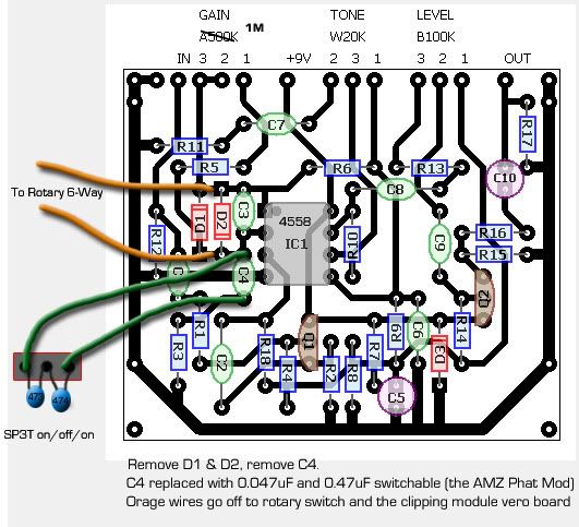 |
|
|
|
Post by flateric on Feb 11, 2010 17:10:39 GMT -5
The innards - not the tidiest worker am i? Heh. 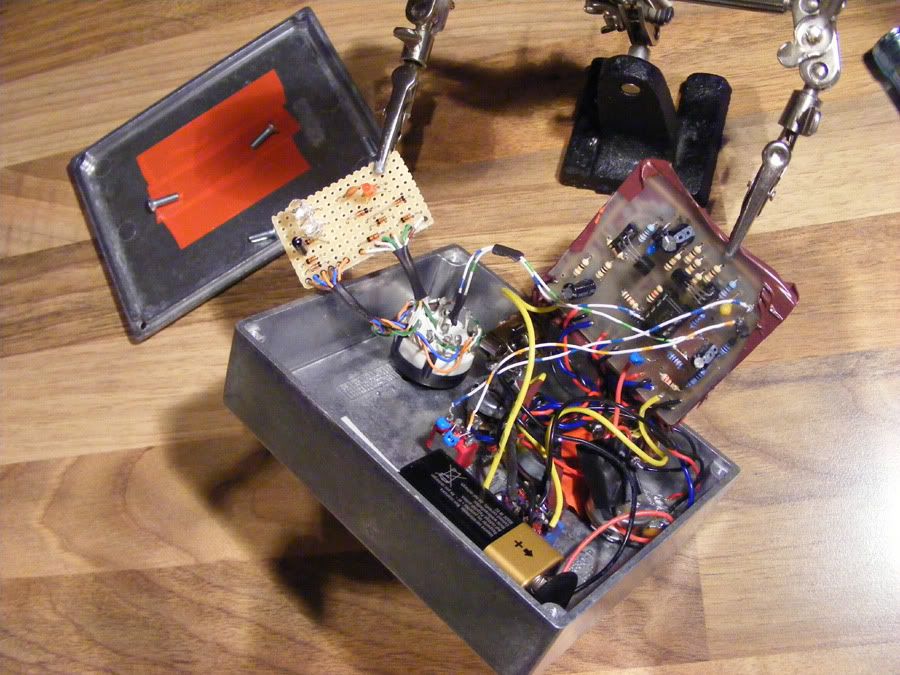 |
|