peterrabbit
Meter Reader 1st Class
 My mileage DOES vary
Posts: 67
Likes: 0
|
Post by peterrabbit on Feb 21, 2011 18:27:17 GMT -5
Hi Kids! Tele body and neck, 2 EMG-HZ passive pups, 2 push/pull 500k pots, True Fender Blender, and this: 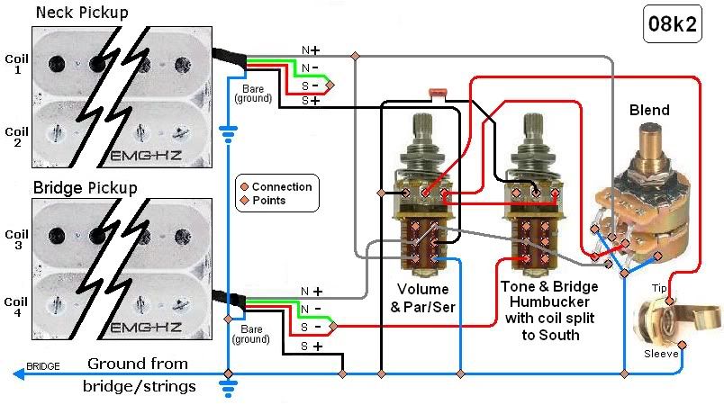 I'm hoping that I can use the blend with both the parallel AND series [between-pups] settings and also with the bridge pup coil-split to south. Anybody see problems with this wiring? Tnx in advance- Peter ------------ Famous Last Words: "Good doggie!" |
|
|
|
Post by Yew on Feb 21, 2011 19:38:23 GMT -5
From what I can tell it looks fine, however do you have your +ve and -ve mixed for the coils 2 and four? I beleive it shouldnt make too much differance, but its a way to make it easier to read. NB; wait for sumagi or newey to say its fine, im not all that great at circuit analysis  EDIT: Ive just realised you have a massive blend pot in the circuit, I have no idea about that, but what I've said above seems to apply for the rest of the circuit |
|
|
|
Post by sumgai on Feb 21, 2011 21:55:05 GMT -5
'rabbit, That diagram sure is pretty - too bad it's got an issue.  Take a look at the left side of the par/ser switch... when it's down, presumably that's the parallel position, right? Well, this ties both N+ leads together, which then means that they're both going to the center tap on each half of the Blend pot - at the same time. Which in turn means that as you rotate said pot, the wiper is heading for ground on one half or the other, and that's gonna take both of the pickup's hot leads out of the picture. IOW, you'll get lesser and lesser output, as you rotate away from center. I'd bet that's not on your agenda, is it?  The series connection is, humm..... interesting.  But I have confidence in you.  Start by fixing the parallel side of things, and I think that the series side will pretty much fall into place. ..... BTW, you've left one half of that P-P empty. The Beta Particle Bombarder may have something to say about that. 'Nuff said. ;D HTH sumgai |
|
|
|
Post by newey on Feb 21, 2011 22:18:55 GMT -5
In addition to the issues spotted by sg, I think the series/parallel blending is not going to operate well in series mode. It will work OK in parallel, not sure what you'll get in series mode. When designing my 4Caster, I was keen to blend the two sets of two pickups together in either series or parallel. ChrisK suggested I would need to add a DPDT switch and do it like this to get it to work properly in series mode: ChrisK's series/parallel blending with a DPDT switchThis added too much complexity- another DPDT switch- so I elected to just combine the two sets of pickups together in parallel with a blender. This solves the problem, but at the cost of losing the "all 4 coils in series" sound- which may be only marginally useful anyway. The "Beta Particle Bombarder" * says that one half of a DPDT won't solve the problem- you need a whole DPDT. *This is a throw-back to a comment I made so long ago, I don't even remember the context or what I said. But sg apparently has a memory longer than my wife's . . . |
|
|
|
Post by ChristoMephisto on Feb 24, 2011 9:13:05 GMT -5
|
|
|
|
Post by JohnH on Feb 24, 2011 14:30:25 GMT -5
Thats a great read, from the early days way back there before GN2. There's some nice diagrams, and a rather quirky way of wiring a blend pot!
J
|
|
|
|
Post by ashcatlt on Feb 24, 2011 16:36:35 GMT -5
I've got problems with that link, there.
Mostly his characterization of a volume control as a variable resistor. It ain't. It's a proper potentiometer, or voltage divider. That's why we use all three lugs. Contrary to what the poster says, there's no Les Paul I've ever seen wired with a variable resistor in series with the pickups. Don't happen, nope.
A variable resistor in parallel with the pickup is a tone control which goes to silence at 0. A variable resistor in series with the pickup is a tone control which does not go to silence at 0.
It's great that your boy likes the way his blend pot works, but if it's actually wired the way he describes (didn't really inspect the diagram) then it ain't actually blending the way we normally think of it.
|
|
peterrabbit
Meter Reader 1st Class
My mileage DOES vary
Posts: 67
Likes: 0
|
Post by peterrabbit on Feb 24, 2011 19:30:39 GMT -5
Okey dokey, how about this, then? Any better? 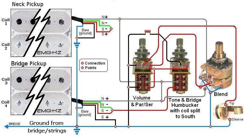 Will this get me blending in both Series AND Parallel? One of these days I'll really understand these concepts - I just know it! Peter --------------- Famous Last Words: "She's just hibernating - give me a stick, I'll show you." |
|
|
|
Post by JohnH on Feb 24, 2011 19:31:12 GMT -5
I enjoyed the bit where he proposes a series/parallel switch using just a single spst. All good, but when you flick it, the volume pots change position and also work backwards! I love intuitive ergonomics.
J
|
|
|
|
Post by ashcatlt on Feb 24, 2011 20:21:10 GMT -5
Hint #1 - You can't get a series connection between two components if both of them have one end connected to circuit ground (or the same place in general). Look at your black wires.
Hint #2 - once you've fixed that, you'll have (in series mode) the bottom of one pickup connected to the top of the other. If anything (blend pot) connects the top of that pickup to circuit ground (where the bottom of the other pickup lives), then you've shorted the whole series structure.
Hint #3 - think of the blend pot as independent V controls (like on an LP) wired opposite one another, across their respective pickups (per Hint #2), and before the S/P switch.
Hint #4 - Now you'll find that, when (in series mode) you roll all the way to one pickup or another you've got a significant amount of resistance in series with that remaining pickup, which will suck tone. You can live with this and only use the blend pot (in series mode) near the center of its travel for subtle changes to the series tone. Use parallel mode if you want just one pickup. Or you can use a 4PDT S/P switch to short the output wire from each side of the blend pot to its respective wiper. It's impossible to do with a push/pull.
HTH
|
|
|
|
Post by ChristoMephisto on Feb 25, 2011 9:15:13 GMT -5
Or toss the Blend pot and make it two volume, one tone
No pup selector switch? Looks like your pups are always 'on' and you have to fully rotate the pot to get just one pup.
|
|
|
|
Post by JohnH on Feb 25, 2011 15:48:17 GMT -5
My thinking is that the blending of pickups is tricky. I haven't tried these 500k true-blend pots, but I have done quite a few tests with pairs of volume controls of different values, and other types of blending. I think the ChrisK diagram, as linked by newey above is the best way to use them, but there are still some issues to consider: In parallel mode, the blending system is like two reverse-wired volume controls, so that one pup can be turned right off without cutting both. On Lps, with 500k pots, if one pup is at 100%, only a small reduction of the other pickup will make it fade audibly out of the mix. In the context of the blend pot, that would mean that you get both on fully at the mid position, but only a very small turn from the centre detent and it will go mostly to just one pup. In series mode, one pup is bypassed by a pot section of reducing resistance, while the other has 500k across it. Ive done series-blender controls with a similar arrangement, and the main blending action only occurs once the reducing resistance gets below about 100k. That would mean in this case, in series mode, most of the action is right near the ends of the travel. Both of the above factors would tend to a conclusion that the pot values should be lower, but to do so adds more load to the pickup, hence losing treble. Just my opinion: But I usually don't find that part-blended mixtures in parallel are particularly interesting, and don't find that they add anything further than the full 100%:100% combos, and the single pup sounds. But I find series blending much more useful. Series blending can work very well using a single 250k linear pot, open it up and remove a section of the track at mid turn. The overall pot resistance is then infinite, and you can turn it to smoothly diminish one pup or the other. The pot resistance from centre to end is just 125k, so the blending action is much better spread out than with 500k. (see Strat Dual-sound ) But, having said all that, these blend pots do seem to be well liked on basses, so I guess my main suggestion is to rig something up to test and experiment before locking into using them. In my case, I would probably go either with two volume controls, or just the series blender and master volume. I did however, make one series/parallel blender that did work quite well, on the ToneMonster2. This was a toggle-switched Strat design, using a blender made from a standard dual-gang linear 100k pot, with a centre detent. The series half used the track-cutting idea above, and the parallel part had output from the wiper and pups connected to each outer lug, so it mixed from one to the other. To smooth the parallel blending and keep the treble snappy, the 'parallel' pot section was bypassed with resistors and caps. The trouble is, I bought three of these pots, but have never seen anymore since! cheers John |
|
peterrabbit
Meter Reader 1st Class
My mileage DOES vary
Posts: 67
Likes: 0
|
Post by peterrabbit on Feb 26, 2011 19:11:25 GMT -5
Is this getting me any closer? 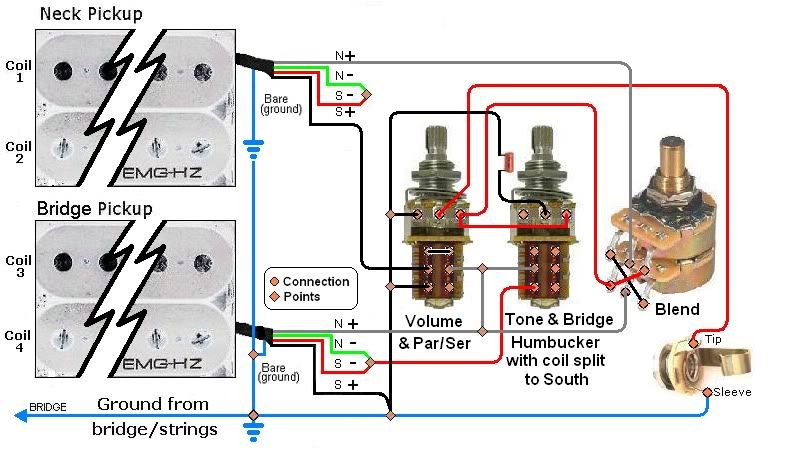 Ya know, when I listened to JohnH's Strat in The ToneMonster2 thread: guitarnuts2.proboards.com/index.cgi?board=schem&action=display&thread=3121, I didn't really like the series sounds, quite muddy IMHO. Maybe I'll just forego that Ser/Par part - it would certainly make the wiring easier! Dunno - just noodling. I was thinking of wiring it like a Les Paul (in one of its billions of permutations,) but in a tele body I want to keep the number of visible controls to a minimum. ASH - "Or you can use a 4PDT S/P switch to short the output wire from each side of the blend pot to its respective wiper." - I happen to have a few 4P2Ts, how would that wiring look? I hope everybody's having fun! Peter ---------------------------- Favorite Country Song Titles: I came back to my fourth wife for the third time to give her a second chance to make a first class fool outta me. |
|
|
|
Post by ashcatlt on Feb 28, 2011 0:25:55 GMT -5
Four coils in series through a clean amp can come across pretty dark. Especially if their "overwound" or "hot" HBs to begin with. You might call it muddy. I've found uses for it, though. Mostly in layering under other guitars to add some weight to the bottom end, or conversely in very sparse arrangements where it's not competing with much in the top end and the detail doesn't get masked. Where it really is cool, though, is when you use the extra output to push the front end of an amp into overdrive. Here the missing higher harmonics won't themselves generate multiples in the distortion, and that frequency range is filled in with multiples of the lower frequencies which do come through. It's less fizz and harsh and more crunch and growl and makes me very happy! Anyway, here's what I had in mind. Note that I've never personally tried this blending thing, and would definitely defer to JohnH when it comes to actual practical applications. I think it works theoretically though.  Of course, I get confused with pot lugs and the CW/CCW thing. You might need to mirror the connections on the blend pot, and if it's a true blend (not pan) pot, you'll need to carefully choose which element is which. |
|
peterrabbit
Meter Reader 1st Class
My mileage DOES vary
Posts: 67
Likes: 0
|
Post by peterrabbit on Mar 4, 2011 13:27:37 GMT -5
Hi folks. Well, after further researching, rewiring and re-thinking this thing, I MAY have sumpin that worx!. What do you think? 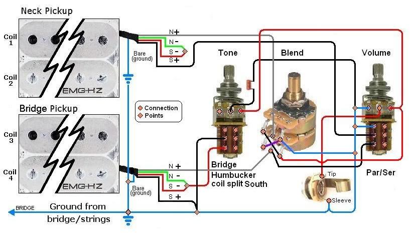 Ash, you've been an inspiration (as usual) and I thank you, in particular, very much. Of course, great thanks also go to everybody else - Yew, Sumgai, newey, ChristoMephisto and JohnH - as well. You guys are great, and a lot of fun. Ash: "Or you can use a 4PDT S/P switch to short the output wire from each side of the blend pot to its respective wiper."I wanted to see about this wiring before attempting to insert the 4PDT circuitry. Peter ------------------- Favorite Country Song Titles - "Hand me the hammer Mama, there's a fly on Papa's head." |
|
|
|
Post by JohnH on Mar 4, 2011 15:47:45 GMT -5
Hi folks. Well, after further researching, rewiring and re-thinking this thing, I MAY have sumpin that worx!. What do you think? I fear not. Parallel mode would be OK (which is the pulled-out setting), assuming this is a true blend pot in which resistances from the center lugs at mid setting, to the outer lugs are 0k 500k, and 500k 0k respectively. That being the case, both hots are connected to the output at the parallel mid setting, which is what you want, and if you turn the blender, resistance is added to one or other pup to diminish it contribution, also good. But, assuming that is all happening in parallel mode, then in series mode, I think the neck pickup is bypassed at mid setting, not good. ChrisK's diagram posted earlier by newey is the way to go for this set up. John |
|
peterrabbit
Meter Reader 1st Class
My mileage DOES vary
Posts: 67
Likes: 0
|
Post by peterrabbit on Mar 4, 2011 20:29:04 GMT -5
Hi John. I'm afraid that I still don't speak schematic - if you know of a good site for teaching the relationship of schematics to diagrams... - anyway, would a standard Par/Ser wiring work here? Also, have a look at this: 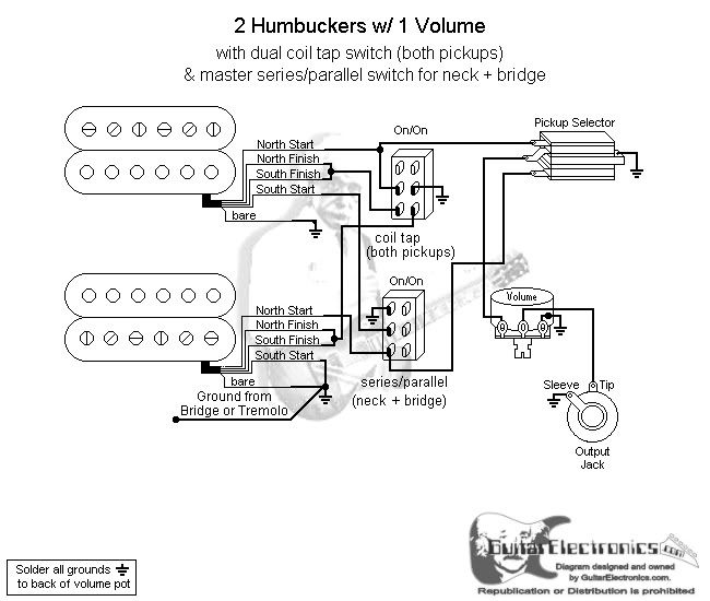 If this works, why doesn't mine? The only diffs are the blend pot instead of the toggle 3-way, and the removal of the neck pup coil split. Could it be the coil split? Oh, yeah, and the tone control, but I can't see that as the prob. STILL workin on it. Peter -------------- Famous Last Words: "It's O.K., nobody ever comes down here." |
|
|
|
Post by JohnH on Mar 4, 2011 22:38:37 GMT -5
If this works, why doesn't mine? The only diffs are the blend pot instead of the toggle 3-way, and the removal of the neck pup coil split. Could it be the coil split? Oh, yeah, and the tone control, but I can't see that as the prob. A fair question indeed. The GE schematic that you posted there has a series/parallel switch that works in a similar way to the original Gibson Jimmy Page scheme, in which to get series mode, you have to push the main toggle to one side in addition to pulling the knob, otherwise one pickup is bypassed. Thats exactly what is happening on your diagram, but it would not be good there because the intention is that you can have series mode with the blender set whearever you want instead of only in one place. Ill think about how to relate wiring diagrams to schematics, it might be a useful thing to have for reference. John |
|
|
|
Post by newey on Mar 4, 2011 23:10:56 GMT -5
PR- ChrisK's drawings were quite different from most schematics you'll see. I think it was sg who said it was like he was shooting for first prize in Industrial Art, or something like that. You can figure this out, and translate it to a wiring diagram you can use, with a few tips. First, "upwards" and "downwards" are used instead of "hot" and "ground", since this is only one module in a larger scheme. "Upwards" goes to the hot out, maybe to the Vol pot, maybe to the jack hot, depending on the scheme in question. Second, the dark blue lines represent the signal flow for parallel (right-hand diagram) and series (Left-hand). The lighter-colored wires are the ones not active in each switch position. Third, connections between wires and/or components are shown as white dots; wires which cross but have no white dot are not connected. And this shows you the rest of what you need to know about the diagram: 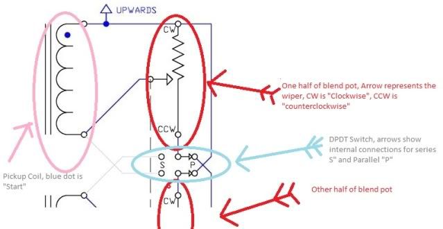 What JohnH and Ash have been saying, I think to put it simply, is that it is not enough to simply mate a series/parallel switch to a blend pot- the wiring to the pot itself differs depending on whether we're blending in series or parallel. The switch needs to switch the wiring to the terminals of the blend pot, not just the wiring from the pickups. |
|
peterrabbit
Meter Reader 1st Class
My mileage DOES vary
Posts: 67
Likes: 0
|
Post by peterrabbit on Mar 5, 2011 16:05:29 GMT -5
Does THIS equal THAT? 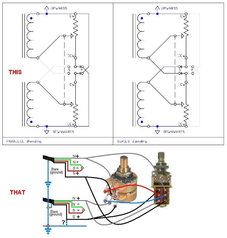 As in, am I reading this correctly? And where are the hot and ground connections? Should the bridge's S+ be grounded? Peter |
|
|
|
Post by newey on Mar 5, 2011 16:52:57 GMT -5
Yes. That's the "downwards" connection.
"ground" is "downwards". "upwards" is "hot". Understand that the reason ChrisK tried to avoid using the terms "hot" and "ground" is that they are incorrect terms as applied to an AC guitar circuit, and can become confusing under certain circumstances.
In your case, upwards would go to the Volume pot, which would be wired as any other volume pot would be, and a tone pot if desired. Or, it could go to other switching, perhaps a middle pickup switch.
Modular is. ;D ;D
Otherwise, it looks good! But let's await a double-check to verify it. Anyone else willing to sign off?
|
|
|
|
Post by JohnH on Mar 5, 2011 16:59:43 GMT -5
Very close, one more iteration needed:
On Chris' diagram, the wires that go from pot outer lugs to switch centre lugs, one comes from the clockwise end (CW) and the other counter clockwise(CCW). Currently, your one has both from the CCW end, so, outer connections on one of the pot halves need to swap. But I don’t know which one, and its important! Its do to with which half of the turn of each pot has the 0k resistance, and which has the 500k. I don’t know if there is a standard, but i suggest a test.
Lets say you view the pot exactly as your photo diagram, and with pot set to midway, you measure resistance from upper mid lug to upper left lug, and find a low resistance. As I see it (someone please also check), then you must swap the connections to the outer lugs of the lower pot. If that test shows a high resistance, then instead, swap the outer connections to the upper pot.
Now, lets say that test showed low resistance. Turning the pot counter-clockwise will keep the upper pup at 100% and the lower pup will be reduced. A counter-clockwise turn on your guitar would logically favour the bridge pickup, therefore the upper would want to be the bridge pup and the lower would be neck. If the test showed a high resistance, vice-versa, the upper pup should be neck.
Output is from the upper pup, grey wire as currently drawn.
I agree with your dotted ? grounding wire.
When you indicate + and -, Im assuming these are start and finish
Not sure what colour code you have, but if it was Seymour Duncan, the wire colours would be, top to bottom, bláck, white, red, green, so whites and reds get joined.
Keep going - this diagram will become a long term reference!
John
|
|
|
|
Post by newey on Mar 5, 2011 17:19:11 GMT -5
OK, John and I stepped on each other's posts, but he and I are saying the same thing.
I looked long and hard at the blend pot, trying to remember how the CW and CCW were; I was thinking they were diagonally opposite, top to bottom, but after reading John's post I think he's right, you need to switch those 2 wires.
Also, bear in mind that, when drawing a diagram, it is sometimes clearer to show one wire splitting into two, like a "Y" as you have done. But, in wiring it in the real world, a jumper between the 2 components is all that's needed.
|
|
peterrabbit
Meter Reader 1st Class
My mileage DOES vary
Posts: 67
Likes: 0
|
Post by peterrabbit on Mar 5, 2011 21:22:10 GMT -5
John: Look at the pups and you'll see that they're EMG-HZs, they are passive, and the wire colors are correct, "+" and "-" are Start and Finish, respectively. O.K. all, try this one: 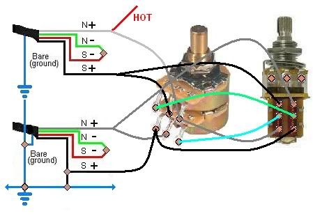 If it's good, I'l try to introduce the rest of the circuitry. I should mention that the reason I want to split the bridge pup (and use a blend) is that the DC resistance is 16.67k, compared to 7.48k for the neck pup. Peter |
|
|
|
Post by JohnH on Mar 6, 2011 6:04:08 GMT -5
yes I think so - seems ok, provided the swap of the pot wires was informed by the resistance test (or other data)
John
|
|
peterrabbit
Meter Reader 1st Class
My mileage DOES vary
Posts: 67
Likes: 0
|
Post by peterrabbit on Mar 6, 2011 17:16:47 GMT -5
O.K., I think this should do it, unless anybody sees further mis-wirings 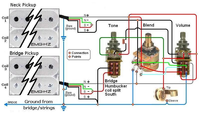 If it is, what's the next step for including it (or parts) in the Truly Nutzoid or Design Modules sections? (if it's worthy of course) Thanks again everyone - this has been a real learning experience for me! (I just hope I can remember it all) Once built, I'll try to post sights and sounds. (that will be my first attempt at such an endeavour) We'll see how that goes. One more thing - can I assume the pot casings want to connect to ground? Peter |
|
|
|
Post by JohnH on Mar 6, 2011 21:38:30 GMT -5
yes, all pot casings to ground. PP pots have a handy tab at the back of th switc that yo can use. Careful withthe blend pot, sometimes i just solder a grounded wire to a washer and put that over the shaft to ground it, to save heating up the pot. Bridge gets grounded too of course.
As to posting your design. Your diagrams are very nicely done, and I think it should go in the general schematics section. But I suggest holding off before posting until you have it built and tested, so that you can make sure you are happy with the blending action, and any other tweaks and bugs are sorted.
cheers
john
|
|
|
|
Post by sumgai on Mar 6, 2011 23:55:46 GMT -5
PR, I think there's gonna be an issue with the Tone control, as currently shown. As I see it, you've connecting both ends of it across the high-side and wiper of the Volume control. In essence, you've just made a 'tunable' Treble-Bleed circuit. I'm guessing that's not what you intended. Also, unless I'm missing something, the left-most terminal on your Volume control does not appear to be grounded (as far as I can tell), which will render that control nearly useless. I must be getting lazy, I'm stopping at two perceivable errors....  HTH sumgai |
|
peterrabbit
Meter Reader 1st Class
My mileage DOES vary
Posts: 67
Likes: 0
|
Post by peterrabbit on Mar 7, 2011 3:20:13 GMT -5
Sumgai:
I'm not sure what you mean by "high side" of the Volume control. If you mean the dark green wire, that was supposed to be part of the "FEZZ PARKA" mod. Don't gotta be there.
As for the grounding issue - right you are - will ground that, and all pot casings.
And, yes, it does help a great deal, thank you.
Anybody else wish to chime in?
Peter
|
|
|
|
Post by sumgai on Mar 7, 2011 4:39:42 GMT -5
PR, 'High side' of the pot means the ungrounded end of the resistance element, and also not the wiper. It's the end where you connected the outgoing 'hot' wire from the neck pickup. Looking at your diagram again, this terminal (the right-most on the Volume pot) connects to the right-most terminal on the tone pot, as well as the pickup. This connection between the Tone and Volume pots is normal. However, the green wire from the other end of the Tone pot, that's not normal - it shouldn't be there at all. Meaning, this terminal shouldn't be connected to anything (unless you're gonna pull the old "spin-a-select" trick). The capacitor should not be going to the wiper of the Volume pot, it should be going to ground. That will make this a master Tone control circuit, which I think is what you had in mind, eh?  HTH sumgai |
|


 But I have confidence in you.


