|
|
Post by fenderbender on Jan 20, 2012 19:11:50 GMT -5
Been thinking about doing something Tele and decided to have a go at translating the schematic (final revision) to a wiring diagram. Found out I pretty much suck at interpreting schematics and should ask for help before I got any further. I'm not sure how a the super switch should be drawn from the schematic. Started by making all the pots and switches as they would be mounted on the control plate (pots rotated for easier understanding) and made a few lines. Then it hit me that I might not have a good enough grasp of the 5 way workings. Just to ease explanation I made an image with a couple of lines and the one I'm curious about is the red line shown on the switch (as I see it) and outlined in the schematic (blue line connected at lug 4 and 2). Is this right or am I way off? Image here: i.imgur.com/Jk2VM.pngAnother thing I'm not sure of is the pots. Are they drawn right (eg: volume and tone are in the right order)? Also the pot lugs and their connections are confusing to me. Guess I don't want it drawn for me but some guidance on how to do it. In other words - maybe one shown and I can try and work out the rest. Any help greatly appreciated. |
|
|
|
Post by reTrEaD on Jan 20, 2012 21:37:19 GMT -5
Another thing I'm not sure of is the pots. Are they drawn right (eg: volume and tone are in the right order)? Yes. Inner knob controls the section farthest from the mounting plate Also the pot lugs and their connections are confusing to me. CW (clockwise) is the lug to the left in your drawing. CCW (counter-clockwise) is the lug to the right in your drawing. I'm not sure how a the super switch should be drawn from the schematic. You have the connections wrong in the drawing you began. When you move the lever to the right (toward the bridge), the pole (common) connects to the throw on the far left (1). C 1 2 3 4 5 1 2 3 4 5 C C 1 2 3 4 5 1 2 3 4 5 C |
|
|
|
Post by fenderbender on Jan 20, 2012 21:49:37 GMT -5
Thanks, reTrEaD. That gives me a start now. Sure I'll have more begging and grovelling later on.
|
|
|
|
Post by reTrEaD on Jan 20, 2012 21:55:22 GMT -5
k, koo  |
|
|
|
Post by fenderbender on Jan 20, 2012 22:35:09 GMT -5
Just when you thought it was safe to... Anyway, I want to make sure I understand your C12345 etc above. Here's another image I color coded (it's like crayons for an old guy so bear with me). Is this going in the right direction or do I need to swap it around? Image: i.imgur.com/Om8Jj.pngI almost think they all need to be swapped - blue for orange and red for green. ?? And last thing (you know that's a lie) is the blender on the schematic. Does the lower drawn portion of that correspond to the bridge part on the pot? |
|
|
|
Post by newey on Jan 20, 2012 22:56:34 GMT -5
Yes.
Now, the rest of the post had me scratching my head:
Not sure I know what you mean. The 4 poles of the real switch are all identical- and interchangeable. You can wire any of the poles, as shown on the schematic, to any pole on the real switch, whatever layout is easier is fine.
Usually, it's best to try to keep the jumpers to one side of the switch, so that you don't have them crossing underneath the switch, but that's just a matter of neatness in wiring. And sometimes jumpering across is necessary.
|
|
|
|
Post by fenderbender on Jan 20, 2012 23:17:56 GMT -5
So...lug 5 is lug 5 regardless of where it is on the physical switch? Hmm, makes me wonder how tidy this thing can get. Within reason. Thanks, newey.
|
|
|
|
Post by fenderbender on Jan 21, 2012 12:16:58 GMT -5
Could someone proof what I have so far please? i.imgur.com/4v9mb.pngI question my interpretation of the mini toggles in particular. |
|
|
|
Post by asmith on Jan 21, 2012 12:57:06 GMT -5
Fb, Lug 5 is not "Lug 5 regardless of where it is on the physical switch." The poles must be intact. If a certain lug corresponds to a certain common pole, it has to stay like that. Looking forward to draft #2. |
|
|
|
Post by fenderbender on Jan 21, 2012 13:17:25 GMT -5
Well crud. Here I thought I was doing so well.  OK, then. Round 2. Also...I think Chris was an evil genius for posting this. |
|
|
|
Post by sumgai on Jan 21, 2012 13:48:07 GMT -5
.....I think Chris was an evil genius for posting this. Oh come on, give the man credit where it's due - he was an evil genius without having to post a bleepin' thing at all! ;D OIOW, he's looking down at you right now and saying "Yeppers, snagged another one, hehehehe!"  ;D |
|
|
|
Post by fenderbender on Jan 21, 2012 15:32:22 GMT -5
Oh come on, give the man credit where it's due - he was an evil genius without having to post a bleepin' thing at all! ;D OIOW, he's looking down at you right now and saying "Yeppers, snagged another one, hehehehe!" ;D I won't argue that at all. Welp, here's what I have done so far: i.imgur.com/vCSwb.png I labelled the poles and transposed all connections to the wiring diagram. I think. Pretty sure they are all accounted for anyway. The caps are not marked for their values yet as I want to just concentrate on the connections for now. I'm cautiously optimistic about the Series / Parallel and pickup Mode switches. Though I'm still not sure they are 100% correct in how I connected them. Can they be wired as shown? Next thing on the agenda is the pickup wiring but I have to ask about the SD colors and the start - finish and their connections to the 5-way and the toggles. Looking at the schematic, how would the those wires translate to the SD color codes? EG: would the neck north upper most wire be SD black? This Seymour Duncan set is what I'm thinking would be my choice. Not going to bother modifying a Fender noiseless bridge to keep exact to the original as Chris penned it. Figured they should be matched and the sound samples there nice. As always, thanks for any replies. |
|
|
|
Post by fenderbender on Jan 21, 2012 17:17:38 GMT -5
Forging ahead, wrong or otherwise, yielded this: i.imgur.com/Urzhk.pngThis is starting to get complicated.  |
|
|
|
Post by newey on Jan 21, 2012 18:03:32 GMT -5
fb- Sorry, but your latest efforts are for naught. The problem is that you are not reading ChrisK's schematic correctly. This is understandable because Chris's diagrams don't look like anyone else's. Sumgai once said his diagrams looked like he was competing for some Industrial Art award. It's sort of a schematic, sort of a diagram, and unlike either one. Let's look at how Chris depicted one pole of the 5-way switch. I've removed the wires to show just the switch lugs. Review this, and I think you'll see where your diagram has gone awry . . .  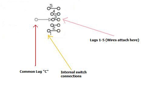 |
|
|
|
Post by fenderbender on Jan 21, 2012 18:22:27 GMT -5
Ugh... I'm trying to wrap my head around that and if I get what you're saying then the orange wire on my last image with the joint is incorrect (as one example). To be honest, I'm not sure how to revise that without being shown. That probably also means the pickup leads (black) in my image are also connected improperly. How am I doing so far? Luckily this is being done in Illustrator so changes are fairly painless. |
|
|
|
Post by newey on Jan 21, 2012 19:03:36 GMT -5
Yes, the pickups connect to the common "C" lugs, not to lug #3. Chris' diagram just shows the switch as if set to position 3 by default. In position #1, the "C" arrow would be pointing at #1, in position #2 the arrow goes to lug #2, etc.
In your diagram, none of the common lugs were connected to anything; in ChrisK's diagram, they are all connected to something . . .
Chris didn't designate the common lugs with a "C", as it's implied as a common lug by virtue of the arrow, to connect it to lugs 1-5 in succession.
|
|
|
|
Post by fenderbender on Jan 21, 2012 20:40:57 GMT -5
Time for a break but here's what I have now. Figured it would be easier to check these out in stages so I hid some of the lines in the first two images. Caps and jumpers.Pots and switches.Everything together.The pickup wiring is still making me doubt my placements but I'm OK with that as it can be changed. EDIT: Wiring is a royal pain in the you know what for me. However, I can do stuff like this in my head, draw it out, make it happen in wood: Stuff I'm better at. |
|
|
|
Post by newey on Jan 21, 2012 22:31:02 GMT -5
You seem to have swapped some of the poles around. The Vol pot CW lug goes to P1 Common, not to P3 Common.
Neck pickup black goes to P2 common, not to P4 common as you have shown it.
Bridge switch common goes to P4 common.
Neck switch common goes to P3 common, not to P3 lug 3 as you have it (the blue wire from P3 lug 3 has to move over to P3 common, and the orange wire from P3 common to the Vol pot has to move to P1 common.)
There may be more, I stopped after those 4.
|
|
|
|
Post by fenderbender on Jan 21, 2012 23:17:01 GMT -5
Talk about a dim light bulb here, eh? It didn't click that the commons were associated with the poles. Anyway, here's maybe an easier method of looking at this monstrosity. Made a layered PDF file so the different 'sections' can be viewed singularly or all at once. Just open in reader and click on the layer icon to select which ones you wish to view. Oh, and I did move the connections you mentioned, newey. PDF here. |
|
|
|
Post by newey on Jan 22, 2012 0:44:37 GMT -5
fb-
So far as I can see, it looks good. But this is a complex scheme, so let's wait for someone to back me up on this before you start wiring. I'll want to do a thorough look-through tomorrow as well.
However, I may see an issue. ChrisK's diagram is for one SD pickup combined with a Fender pickup, and these are wound opposite of each other. You're using matched SD pickups.
See how Chris placed a black dot by one end of each coil? That designates the end of the coil that we will arbitrarily call "hot" (or you can call it "Start", or you can call it "the one with a black dot"). It's important only so as to designate one end of the coil winding from the other.
Notice that his black dots are mirror-imaged between the two pickups. As are his designations of "top coil" and "bottom coil". I'm thinking that yours should not be- meaning that the green wire from the bridge pickup probably needs to swap places with the black, and the white swaps with the red.
This is only so as to have the phasing correct.
But, again, let's let another pair of eyeballs have a look at this, I could be wrong on that.
|
|
|
|
Post by fenderbender on Jan 22, 2012 0:52:09 GMT -5
Believe it or not I actually had it drawn that way at one point and then hedged my bet lol. I agree that it should be vetted before commencing any work. Thanks again, newey, for taking the time to check it out. |
|
|
|
Post by fenderbender on Jan 22, 2012 11:29:24 GMT -5
newey-
Changed the wire colors so if anyone grabs the PDF they can read it easier. Same link should work.
|
|
|
|
Post by fenderbender on Jan 24, 2012 12:01:20 GMT -5
One last question with this...should the back of the pots be earthed/grounded? My clueless nature says yes but just wanted be sure.
|
|
|
|
Post by newey on Jan 24, 2012 12:30:48 GMT -5
It may not make any difference to ground the pot shells, but it may reduce noise. It's probably a good practice to do so.
|
|
|
|
Post by fenderbender on Jan 24, 2012 12:49:49 GMT -5
Thanks, newey. PDF above has been updated. Eh, did anyone else look and confirm newey's findings that it was drawn correctly?
|
|
|
|
Post by newey on Jan 24, 2012 18:38:23 GMT -5
Diagram checkers to aisle 4 , please! ;D
I'll look at it again, fb, although work calls this evening. But another pair of eyeballs would be helpful!
|
|
|
|
Post by fenderbender on Jan 25, 2012 13:38:30 GMT -5
Got to thinking about this in a different light and noticed that it might be a neat thing to toss into a JR style (or whatever) flat top guitar with four pots. So that lead to breaking up the controls and moving to four positions. Then it occurred to me that the series / parallel switch could be a push-pull pot. However, I'm not certain I have the orientation of the p-p correct. So here's an image with a lot of the other bits hidden. i.imgur.com/qGNlB.pngI'm thinking up for series so did I hit it right or does there need to be a flip flop of the wiring up there? |
|
|
|
Post by fenderbender on Jun 8, 2013 18:02:36 GMT -5
Hey newey - I was digging around through some files and ran into this monstrosity again and decided to make the changes you mentioned and clean up some of the routing. Should be a little easier to follow (yeah right, given this circuit's complexity) along the drawn paths now. I had also found another error with the volumes (CW lug) wire to the common lug. That should be OK now. The PDF is done in layers yet so you can show or hide them to make it a little less challenging to ferret out where what goes where. One other thing missing is the volume mod. Chris never put numbers there but I am assuming it was for whatever flavor of treble bleed one preferred. I may add that in later, but for now there's enough crap in the way as it is. dl.dropboxusercontent.com/u/5212875/chriskteleblender.pdf |
|


 ;D
;D
