|
|
Post by darkavenger on Feb 10, 2012 20:41:04 GMT -5
Hey there!
I just ordered a few piezos along with my last mouser order and I've been having fun moving them around and see what types of sounds you can get from them. For testing, I've just wired a jack to two piezos(still playing with series vs parallel) and I've been running them through my zoom effects pedal for a buffer. I've been giving some thought to the final wiring, I'm thinking I want to keep things simple and try for a one knob solution. I have seen a few EQ schematics and I think I understand what is going on, so I don't think it would be to hard to make a simple EQ with two or three channels and mix them with a blend pot to get a wide range of shaping in one control. I was wondering if anyone had any input or suggestions?
|
|
|
|
Post by JohnH on Feb 10, 2012 21:30:49 GMT -5
Hello darkaverger Here's my version: Adding a Piezoin amongst all that, I have a tone shaping stack, with three presets, which I think could also be quite good as variable controls cheers John |
|
|
|
Post by darkavenger on Feb 11, 2012 20:48:39 GMT -5
What is your take on this circuit? I've been back and forth on trying it, but I have an extra op amp so I might go for it. I'm not sure if some of those values need to be tweaked or not if I want to blend the output with magnetic pups. scopeboy.com/elec/chargeamp.gifAlso, I've been playing with two piezos in series vs parallel. From what I can tell, series (can) give a volume boost and bring down the highs a bit while parallel seems to give a 'clear' sound but at a higher end of the spectrum. Both piezos remained in the same positions while testing, mostly just on the front of my jag. I used a non-conduct plastic barrier to put pressure on the piezos and I haven't applied shielding. I believe the cable I used is a 6' Planet Wave with gold on the tips plugging into a Zoom effects processor. |
|
|
|
Post by 4real on Feb 12, 2012 2:09:52 GMT -5
Great to see you here DA, there is a mine of info on this subject as I've said  and quite a few piezo applications...JohnH here has offered a wide range of help to many, all of which are great resources... |
|
|
|
Post by JohnH on Feb 16, 2012 3:35:31 GMT -5
Thats an interestng circuit, worth a try if you have an FET input opamp as as stated there. It may need values tweaked however, so be ready to experiment.
What your Zoom processor and how do you set/connect it? I have a G2Nu
J
|
|
|
|
Post by reTrEaD on Feb 16, 2012 9:43:55 GMT -5
Thats an interestng circuit, worth a try if you have an FET input opamp as as stated there. It may need values tweaked however, so be ready to experiment. Amen to the tweaking. This seems a less than predictable circuit.  Since the non-inverting input is biased to +4.5v, the opamp will only be "happy" when the inverting input is at the same voltage. This puts 4.5v dc across the piezo element. Is this a bad thing? I don't know. The gain formula for an inverting amplifier is -Rf/Rin. From a DC standpoint, we know Rf (10M) but what is Rin (internal resistance of the piezo)? From an AC standpoint, the gain will be largely determined by the ratio of Cf to the Cinternal of the piezo. The first thing I'd be concerned with is the voltage at the output pin of the opamp (not the "output" labeled in the diagram). If Rf is too high, the DC at the output pin will be appreciably higher than +4.5v. This would limit how far positive the signal output can go. It might be necessary to reduce the value of Rf. Or skew things by changing the values of R2 and R3 to lower the +4.5v reference at the non-inverting input. At 1000 Hz, the capacitive reactance of 10nF (Cf) is about 16k. This makes the 10M of Rf inconsequential in the AC gain. Even at 100Hz, it's about 160k. Still much lower than Rf. Edit: corrected gain formula for polarity |
|
|
|
Post by darkavenger on Feb 16, 2012 10:29:34 GMT -5
Thank you so much for the input! Something didn't quite seem right here, but I talked to someone who has built the circuit and it does work as shown. He did add in that C1 must be a switching/pulsing type and value be varied from 5-15nf.
Some more information about my piezos:
I have two 30mm 18nf disc elements to be wired in series. I believe this will result in 9nf with quite a bit of voltage relative to other piezos. I'm pretty sure this is about where I want to be to get a good response to all frequencies, though I'm not sure of the specifics.
I have already planned on getting a cheap breadboard to test this out on, even if it does work as shown, I've been concerned about R2 and R3. R1 and C1 looked a little suspicious, so it's great to have people who really know whats going on to offer their assistance.
|
|
|
|
Post by reTrEaD on Feb 16, 2012 14:12:05 GMT -5
I have two 30mm 18nf disc elements to be wired in series. I believe this will result in 9nf with quite a bit of voltage relative to other piezos. I'm pretty sure this is about where I want to be to get a good response to all frequencies, though I'm not sure of the specifics. If the 18nF spec is correct, two in series would look like 9nF. So a 10nF cap in the feedback loop would give you just a pinch more than -1 gain. Changing this value will affect the gain more than frequency response, unless the value of Rf is much lower than the 10M shown. If you keep two discs but put them in parallel rather than series, you'll have about 36nF. I would expect a little more output in this configuration than in series. Although the input will be half the voltage, the gain will be roughly -3.6 |
|
|
|
Post by JohnH on Feb 16, 2012 14:34:01 GMT -5
Id think two of those in series will create 2x the voltage (if not conected), but also 2x the inpedance at a given frequency relative to C1. So taking acount of the gain of such a circuit, do we get back to about x -1gain again?
I also used these disc elements, and have heard of about 20nF being the capacitance of them - which matched my experince. In my case, I needed a relatively low input impedance (resistor to ground) to roll off sub-bass thumps. 150k worked well for me. In this case, it is R1 that does that job, and may need to be lower than as shown. I had my piezo blocking the trem block, and without this 150k resistor, if I pressed the bridge, it made such a big almost dc pulse that it blocked out the signal for a second or two. I think that was due to how I had it mounted, and also the high capacitance of these large peizo elements.
John
|
|
|
|
Post by reTrEaD on Feb 16, 2012 16:16:04 GMT -5
Id think two of those in series will create 2x the voltage (if not conected), but also 2x the inpedance at a given frequency relative to C1. So taking acount of the gain of such a circuit, do we get back to about x -1gain again? I think this is correct. Putting two in series doubles the voltage, but the gain would be half because of the increased reactance on the input. So we're back to whatever output we originally had with just one. But putting two in parallel has no affect on the voltage, and the gain would be double. So we should expect more output with parallel piezos. |
|
|
|
Post by JohnH on Feb 17, 2012 0:36:02 GMT -5
Agreed, and it should work, but its a bit weird isnt it? No extra volume when in series! It seems to respond to the total amout of charge rather than the voltages - (or sumfink like that)
|
|
|
|
Post by darkavenger on Feb 17, 2012 4:14:04 GMT -5
Alright, so let's sub a 5nf cap for the 10nf(though I will try both when breadboarding). The person I was talking to was using a 24nf piezo and either 10 or 15nf C1. He also said the value of C1 was critical to the sensitivity and 'the -3dB point' or the bass response might be cut off. He works with acoustic guitars, but I don't think that should matter too much here.
JohnH, according to the data sheet the piezo has '18,000pf +/-30%' capacitance, although in reality it may be closer to 20nf.
The value of R1 always looked to high to me and the value of R2 and R3 too low. I wasn't sure if this was on purpose or part of the design, but what might you suggest for these values? I am going to breadboard it, so multiple or a range of values to try would be helpful if one specific value doesn't stand out.
|
|
|
|
Post by JohnH on Feb 17, 2012 4:30:17 GMT -5
Id say R2 and R3 are fine, they dont connect to the signal at all, they just provide a voltage reference to the + opamp input. R1 could also vary widely, if its at least 1M Id say it wont have much effect, but it is necessary to have something there. If you suffer from the sub-bass effects I did, start reducing it, to get a roll below the frequency where the impedance of C1 = R1 - so it depends on C1. Im guessing yopull want a few db of gain, so C1 would be less than the piezo capacitance, so Im guessiing 5 to 10nF, but maybe even less.
off you go and try it!
cheers
John
|
|
|
|
Post by darkavenger on Feb 17, 2012 8:26:56 GMT -5
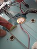
Here are some picture of how I'm planning to mount the piezos. I need to route out small channels for the piezos to fit into and small space for the chip. Any suggestions are of course welcome! 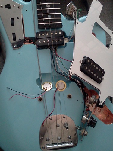  |
|
|
|
Post by reTrEaD on Feb 22, 2012 19:08:39 GMT -5
Agreed, and it should work, but its a bit weird isnt it? No extra volume when in series! It seems to respond to the total amout of charge rather than the voltages - (or sumfink like that) Yes, something like that. The part that stands out in my mind is the fact that the capacitive reactance (part of what determines the gain of the circuit) is internal to the disc, rather than a separate component that we select in the circuit design. So series, single, or parallel affects the circuit gain. Id say R2 and R3 are fine, they dont connect to the signal at all, they just provide a voltage reference to the + opamp input. I agree. R1 could also vary widely, if its at least 1M Id say it wont have much effect, but it is necessary to have something there. In theory, yes. In practice, I'm not certain what the maximum value of R1 could be. It needs to be considerably less than any leakage paths to ground at the inverting input of the opamp. Im guessing yopull want a few db of gain, so C1 would be less than the piezo capacitance, so Im guessiing 5 to 10nF, but maybe even less. Yes. If the gain is too high and the signal from the piezo too large, you run the risk of having so much output that the signal will be clipped. Gain of 2~4 seems a good enough place to start. If you suffer from the sub-bass effects I did, start reducing it, to get a roll below the frequency where the impedance of C1 = R1 - so it depends on C1. The lowest note on a guitar (standard tuning) is E2 (82.41Hz). The capacitive reactance of 5nF @ 82.41Hz is about 386k. I think a 500k or 1Meg trimpot would be a good choice for R1. Here are some picture of how I'm planning to mount the piezos. I need to route out small channels for the piezos to fit into and small space for the chip. Any suggestions are of course welcome! If the body is thick enough, you could deepen the route for the bridge pickup, but you need more room than just for the discs and the board holding the circuit. You also need room for the battery. |
|
|
|
Post by darkavenger on Feb 23, 2012 0:13:34 GMT -5
The lowest note on a guitar (standard tuning) is E2 (82.41Hz). The capacitive reactance of 5nF @ 82.41Hz is about 386k. I think a 500k or 1Meg trimpot would be a good choice for R1. Here are some picture of how I'm planning to mount the piezos. I need to route out small channels for the piezos to fit into and small space for the chip. Any suggestions are of course welcome! If the body is thick enough, you could deepen the route for the bridge pickup, but you need more room than just for the discs and the board holding the circuit. You also need room for the battery. Thank you for your input, always welcome! I'm expecting my order to arrive tomorrow, and yes, I ordered some trim pots. Figured it would be a good idea, thanks for the reassurance! I got a 500ohm and 1 meg trimmer, for R4 and R1. I also ordered a 2.2 and 4.7 nf cap. I was wanting to keep the circuit and piezos together to keep wires as short a possible, but possibly locate the battery in a more accessible location like under the jack plate. I guess I forgot to state that in my last post... I think I'm going to add in a 4pdt push button switch too, something that will be able to not only activate the piezo, but 'activate' the whole guitar as well. I want to keep the ability to play passive, but the piezo and blending require active, so I want it but probably only as needed. Here is what I'm thinking: Piezo / ground (to blending pot) Piezo battery / off(unused) Mag active / Mag passive Mag battery / off(unused) For added battery security, I'm installing a stereo jack on/off |
|
|
|
Post by reTrEaD on Feb 23, 2012 8:28:24 GMT -5
I think I'm going to add in a 4pdt push button switch too, something that will be able to not only activate the piezo, but 'activate' the whole guitar as well. I want to keep the ability to play passive, but the piezo and blending require active, so I want it but probably only as needed. Here is what I'm thinking: Piezo / ground (to blending pot) Piezo battery / off(unused) Mag active / Mag passive Mag battery / off(unused) For added battery security, I'm installing a stereo jack on/off If I read this correctly you'll have two modes of operation: Passive Mag only. Active Mag and Active Piezo with blend. Is that correct? I think you will only need one pole to enable the power for all the active shiz. Another to select whether the output jack is connected to the passive mag or the active blend. And a third to direct the passive mag to the output jack or to the active preamp. The third pole isn't all that necessary. You could just leave the input of the active mag preamp connected when in the passive mode. But since you have 4 poles... |
|
|
|
Post by darkavenger on Feb 23, 2012 13:05:37 GMT -5
Oh yea... that makes sense. Well... what to do with the unused space then?
It would be possible to change the value of the blend pot, I have 500k but it seems like 100k is popular here. Thoughts and opinions?
A tone cap could similarly be changed, but I don't use my tone often.
|
|
|
|
Post by reTrEaD on Feb 23, 2012 14:25:57 GMT -5
Unused space? Do you mean the extra pole on your 4pdt switch? If you don't need it, don't use it.
With a passive system, 500k is a good choice. But in an active system, the lower values are better.
|
|
|
|
Post by JohnH on Feb 23, 2012 14:31:17 GMT -5
If you are planning to have power switching as part of the controls, watch out for the likelihood of stupendously large thumps in the output. They can be controlled by resistors and caps but it is hard to eliminate them. For that reason, my active guitars just have the jack to engage power, so I plug in with the amp turned down and there are no thumps after that - power is running continuously. How will you do the buffer for the magnetic pickup? - the JFET modules work well (see treguires and particularly4real's posts) guitarnuts2.proboards.com/index.cgi?board=wiring&action=display&thread=5970For me, I would do just a single active output, blendable from active mag to full piezo (per the Strat design I linked to at reply 1 of this thread), and then have a passive mag output on its own jack socket. that way you can have fun with stereo outputs and have a simple circuit. cheers John |
|
|
|
Post by darkavenger on Feb 23, 2012 16:15:22 GMT -5
Haha actually I've been talking a lot with 4real, he's been helping me straighten out a lot of rough ideas and been great to bounce brainstorming ideas off of, even if some of them are a bit silly or flawed.
Ok, because I don't think I was clear for anyone who might be reading this, the 4pdt switch when in active/piezo mode makes the blend pot acts as just that. When switched to passive mode, it would act as a volume(linear, not audio)
So about the unused pole in the 4pdt switch. Why don't I add a on/off resistor across the two outside terminals on the blend pot with a value of... 330k? This will bring down the resistance of the pot. Side effects?
Just another thought of how to use the 4th switch, maybe a treble bleed for when in passive mode.
I don't mind a pop when switching back and forth, I wouldn't plan on needing to switch back and forth while playing, but I have left an active guitar plugged in by accident, possibly more than once. and people wonder why I generally don't like active guitars... So really, the LED thing I want to do(a reminder really) along with a backup on/off switch is really just because I don't like my battery dying and ending up with an unusable guitar.
I think a simple JFET buffer on the mag side will be fine, I have a few of those around.
As for the stereo output, it's interesting but I'd like to keep things compact on the surface of the guitar, stuff like switches, knobs, etc I'm not sure where another jack would fit. On the side(LP style) could have worked nicely if I didn't used such a large radius router cut.
P.S. I got my parts this morning.
|
|
|
|
Post by reTrEaD on Feb 23, 2012 18:59:57 GMT -5
Ok, because I don't think I was clear for anyone who might be reading this, the 4pdt switch when in active/piezo mode makes the blend pot acts as just that. When switched to passive mode, it would act as a volume(linear, not audio) erm, okay... Would you have a separate volume control for the active system or no volume control when active? So about the unused pole in the 4pdt switch. Given your update, I'm not sure if there will be an unused pole. Why don't I add a on/off resistor across the two outside terminals on the blend pot with a value of... 330k? This will bring down the resistance of the pot. Side effects? This only changes the loading that the source (pickups) would see, and the resistance when the pot is fully clockwise. When you put the pot in the middle of its travel, a 500k pot will still look like two 250k resistors. One to ground, the other through the source (pickups). So it really won't look much different from a 500k pot without the 330k, in terms of noise rejection on the guitar cable. imho, not worth the bother. Not a side effect, just nothing good happens. Just another thought of how to use the 4th switch, maybe a treble bleed for when in passive mode. Maybe, but in addition to the possibility of not having and extra pole, you have to consider that you're using a linear pot. The resistor/cap parallel combination used for treble bleed (between the wiper and CW lug) affects the taper of the pot. Not all troublesome when using an audio taper, but it pushes the "half volume" point on a linear pot even closer to the CCW end of the rotation than it already is. A linear pot as a volume control is already less than ideal. Treble bleed makes it even worse. So really, the LED thing I want to do(a reminder really) along with a backup on/off switch is really just because I don't like my battery dying and ending up with an unusable guitar. LEDs take tons of current compared with buffers. I would absolutely not run an LED to show the power is on. I'm still very unsure of what you want to have, in terms of what the passive only and the active modes. If you could make a drawing of what you're planning, it would help the discussion.  |
|
|
|
Post by darkavenger on Feb 23, 2012 19:15:55 GMT -5
Update: I got the circuit breadboarded! I tested against no buffer and through my zoom pedal, and there is a big difference. Seriously big. I think this might be due to the cable's capacitance when plugged through the zoom buffer, so I want to test this circuit against a JFET buffer before the cable. Ok, so I'll try to get some audio files uploaded soon, but for now
Charge amp - Very crisp and clear, a bit more high ends then I imagined it would have, probably need to start adjusting some values. I had R1 and R4 set to 750k and 300ohm with 4.7n cap. I will probably add 2.2n cap in parallel
No buffer through small crate practice amp(probably 10W) - sounds ok I guess. A lot more bass, little/no clarity, kind of sounds like someone turned the tone knob to 0 with a hint of broken.
Zoom - similar to no buffer without the hint of broken and a bit more clarity. Still very warm but sounds good in a way.
Testing was done holding the piezos on the back of the strings behind the bridge on the bottom 3 strings only. I'm rethinking my plan of mounting the piezos. I think that one piezo and the circuit will go in the bridge pup cavity, but I think one needs to go under the saddle somehow. More thinking...
|
|
|
|
Post by JohnH on Feb 23, 2012 21:05:31 GMT -5
Electronics can be fun cant it!
One thing about your opamp circuit that is an advantage compared to a simple Jfet buffer is that it should be possible to twist and tweak its tonal response, by using R's and C's around the input, output anf feedback loops. Thia can all be predicted reasonably well by simulation software, such as 5spice. I actually made a test of the base design just because it looks interesting.
So my suggestion would be to choose your piezo posiions to give yourself a good signal, with the right frequencies in it (but maybe not perfect tonal balance), and record a few simple strums direct into your computer. Then a frequency plot can be seen and compared to an ideal such as a nice real acoustic guitar, then you can judge what tonal correction is needed and this can be tested by simulation, then in the real circuit.
So if you put up your best strum sample, recorded with a reference from a mag pickup at the same level for a db reference, the circuit can be configured to make a good result. I'd be pleased to have a go at that if you wish.
cheers
John
BTW, on LEDs in the guitar - I also tend not to. I like onboard circuits to run with low current <0.5mA, and an LED needs about 2mA. So I use less power by leaving it plugged in acooassionally than I would by always using 5x as much power to run the LED.
|
|
|
|
Post by darkavenger on Feb 23, 2012 22:48:35 GMT -5
Ok, fair enough. No LED, but still a backup switch.
I'm thinking of mounting the piezos between the bridge and body now. Since there is only 5-10 lbs pressure on the bridge, all downward, it seems a viable option. I still need to think through all the options, but that is sounding like a good one right now.
I'll try to get a circuit layout up, might be a bit messy though. I also want to find out the power consumption, so next time I get a chance to do some testing I'll find out. Speaking of testing, the mag pups are taken out so a recorded strum will be a bit hard. I'll try to get some recordings up soon, just the piezo for now. Once everything is permanently mounted, I'll get the two strums to match levels.
Hmm... your right about the pot and resistor. New ideas?
|
|
|
|
Post by reTrEaD on Feb 24, 2012 0:05:17 GMT -5
One thing about your opamp circuit that is an advantage compared to a simple Jfet buffer is that it should be possible to twist and tweak its tonal response, by using R's and C's around the input, output anf feedback loops. Thia can all be predicted reasonably well by simulation software, such as 5spice. I actually made a test of the base design just because it looks interesting. Looks interesting, but hard to wrap your head around. In most opamp circuits, gain is determined by the ratio of resistors in the feedback and the input. A cap in the feedback loop is often used to provide HF rolloff. But in this circuit, the gain is determined by the ratio of the capacitors. 5spice sims will be very helpful in determining modifications to this circuit. The resistor and cap on the output currently serve a rather mundane function. Blocking DC and limiting the current in the event of a short. The 10uF cap seems absurdly large. @ 82Hz its reactance is under 200 ohms. Perhaps a low pass filter on the output could be used to tame the HF response, but I wonder if adding resistance in series with the input might be a more manageable approach. idk. So if you put up your best strum sample, recorded with a reference from a mag pickup at the same level for a db reference, the circuit can be configured to make a good result. I'd be pleased to have a go at that if you wish. If I had to bet on who might best accomplish this, my money would be on you, John. I'll try to get a circuit layout up, might be a bit messy though. Messy drawing > no drawing. Atm I only have the vaguest concept of what the overall objectives are. |
|
|
|
Post by darkavenger on Feb 24, 2012 0:29:54 GMT -5
Ok, I'll do it better next time, I was trying the new DIYLC 3.0 and sort of misplaced some things getting used to it. Also, the buffers aren't meant to wired as so... just place holders for now. I think I got everything right... 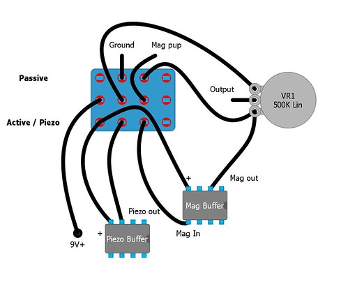 |
|
|
|
Post by 4real on Feb 24, 2012 5:11:01 GMT -5
Not sure why this thread wasn't book marked...oh well, will be now...
I commend DA for his perseverance in this and a lot is out of my league, but I see he is in good hands on a lot of this. The "charge" circuit is interesting and will good to see how it pans out as an alternative perhaps to more conventional buffer designs.
On the 'bypass' thing, I did try it on my guitar for a while there but there was some problem with the HB mag that I couldn't identify and later was taken out to be replaced by a phase switch. The phase switch can be a little useful for matching the mags to the piezos...but not essential.
The bypass thing would still be useful, I still consider if I redo the electronics (not entirely happy with it, bit of hiss and scratchy pots still) but my guitar has three buffers and a piezo preamp so not sure exactly where the problems lie.
I have gone through a few batteries too...but then I play a lot, plus the occasional leaving the thing plugged in does not help. A really good battery helps a lot though.
While the circuits are interesting, do any GN2'ers have an opinion on piezo placement on this kind of guitar (jazz/jag) which has a ToM type bridge of sorts. I ahve doubts about the originally proposed 'side' placement. If done like that, rather than hack into the guitar as DA proposes, I suggest cutting teh piezos, especially the metal surroung that tends to be far larger than the crystals if that will help.
Another suggestion would be to take the 'studs' out and make a 'plate' or even wood and glue/tape the piezos to that and then insert the studs through it so it perhaps maximises vibration. Just a thought, not that familiar with working on these kinds of bridges, certainly the strat is a bit easier and obvious where one might mount it on the trem block.
In the past, I've found a bit of tape is good for testing things and placement on the guitar, best to tune all the strings up I'd say to get a better idea of things.
I also have a feeling some kind of filtering will be necessary to get a good sound out of these things regardless of placement...the offer to use a sound clip to make suggestions is a very generous one.
...
Anyway, good to see some progress and testing going on, it could be a great guitar in the end, but it might be a while LOL...these things often do don't they!
|
|
|
|
Post by reTrEaD on Feb 24, 2012 7:44:37 GMT -5
While the circuits are interesting, do any GN2'ers have an opinion on piezo placement on this kind of guitar (jazz/jag) which has a ToM type bridge of sorts. I ahve doubts about the originally proposed 'side' placement. If done like that, rather than hack into the guitar as DA proposes, I suggest cutting teh piezos, especially the metal surroung that tends to be far larger than the crystals if that will help. I didn't know what you meant by 'side' placement until I looked at the photos again. The second photo does show him holding one of the piezos against the side wall of the route. I didn't get the significance of that the first time I saw it. Now I see the implication. I originally thought he would be mounting the piezos on the floor of the route, after making the route a little deeper. If 'side' mounting, it would make perfect sense to trim the bottom flange. I don't have any personal experience with piezos so I can only speculate about mounting strategies. I've read where some have simply glued the flange to a flat section of the body. While this will produce an output, I think more output (and perhaps a better frequency response) would be possible by "clamping" the piezo element against a flat surface. Of course a relief area in the "clamp" would be necessary to accommodate the bead where the lead is attached to the top of the element. Else a localized pressure point would occur. Ok, I'll do it better next time, I was trying the new DIYLC 3.0 and sort of misplaced some things getting used to it. Also, the buffers aren't meant to wired as so... just place holders for now. I think I got everything right... k, koo. Now I understand the general strategy of the overall system. Comments:The way you've drawn the connections to the volume control would be correct if you were looking at the shaft side of the pot. Normally I draw them as if viewed from the rear. But no big deal as long as we both understand what you mean. Stuff left connected when in passive mode ... Whenever possible I prefer to bypass the buffer completely. Your circuit bypasses the input of the mag buffer. This is a little better than leaving the input connected. Since it's likely to be a fairly high impedance it wouldn't wreak havoc if left connected. But disconnecting it is better On the other hand, the output of the mag buffer remains connected in the passive mode. This is VERY bad. Expect noticeable signal loss and a major league "tone suck". The mag buffer will reduce the load on the pickups. This results in a little more brightness. In most active systems, the low impedance output allows you to use a volume control of much lower resistance, since the buffer prevents the volume control loading the pickups. With a 25k pot, the maximum resistance in series with the output jack is 20 times lower than with a 500k pot. So you will experience less treble loss when reducing the volume control. Even with the volume control at full volume, you'll still get more treble and less cable noise with a typical active system. The low impedance of the buffer makes cable capacitance irrelevant. Also any stray magnetic fields have to work against a low impedance source (buffer). But in your system, most of the benefits of an active system are negated by the blend pot. The low impedance of the two buffers are separated from the output jack by a pair of 250k resistors (the blend pot in the center of its travel). This makes it relatively easy for hum and noise to "penetrate" the cable. And the resistance works together with the cable capacitance to form a low-pass filter. This causes a loss of treble. Finally, you no longer have a volume control, in the active mode. This seems very difficult to manage, imho. Are you sure you can cope with that? Other possible strategies:- Using a third buffer for the output. - Having a second volume control for use only in active mode. - If limited to only two buffers, I think feeding the 'blend' control with the passive pickup signal and using an output buffer, would be far more advantageous than the present strategy. I'm interested in hearing John's opinion on all of this. |
|
|
|
Post by JohnH on Feb 24, 2012 15:32:51 GMT -5
[quote author=retread board=wiring thread=6186 post=61109 time=1330087477
Other possible strategies:
- Using a third buffer for the output.
- Having a second volume control for use only in active mode.
- If limited to only two buffers, I think feeding the 'blend' control with the passive pickup signal and using an output buffer, would be far more advantageous than the present strategy.
I'm interested in hearing John's opinion on all of this.[/quote]
Blend pot value and active output
I also think that the 500k blend pot should not be right at the output, for reasons that retread describes, of losing some of the benefit of a low impedance active output. There are three benefits that I can think of related to keeping overall output impedance low. Since you are going to all this trouble, you might as well have them all:
1. Avoidance of treble loss due to cable capacitance - tone is consistent at all volume settings and you can use any length of cord
2. Less noise induced in the cable - the low impedance squashes it and it helps with cables that are not quite so perfect
3. Ability to DI directly into a mixer or other medium/low impedance input. This is very handy indeed, particularly when your best acoustic-like piezo zing may be when you use a PA system rather than a guitar amp. A good option to have IMO.
But the way this blending arrangement works depends on having a large ratio between the low output impedance's of two active sources, and the higher impedance of the pot. That way, when blended fully one way, a negligible amount of the other source can get by. So if you have the blender right at the output, your output impedance cant be as low as compared to being directly after a buffer.
But, if it is blending between the two op-amp buffers, I suspect that they have quite a good low impedance output, so It should work with a much lower value blend pot. I think the op-amps have output resistance of only a few hundred ohms, and are happy driving loads down to 10k or less, so the blend pot could be cut down from 500k to say 50k if you needed to not have a buffer after it. The highest output resistance would then be 12.5k, which is not bad. Still a bit high to DI into a line-in, but it will work.
Supply current
Another thing to watch for when thinking about adding chips, is that according to the specs, these op-amps take about 1.4mA each, so two of them, plus biasing etc, will need about 3mA, so reckon on about 100 hours from a 9V battery. (The JFET circuits that I use for the same functions take 1/10 of this).
Magnetic buffer
If you are using an op-amp for the mag buffer, it will need a more conventional circuit than this charge amp. ie, it will have a feedback loop with resistors instead of a capacitor
Volume control
Also, to keep control of the two signals, will you have a normal volume control after the mag pickup before its buffer? that way in passive mode you can take out the blender completely (necessary if the blender is a low value), and in active mode, by adjusting blend and mag volume, you can set any mix and volume that you wish - works for me anyway.
cheers
John
|
|


 and quite a few piezo applications...JohnH here has offered a wide range of help to many, all of which are great resources...

